1
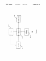
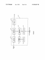
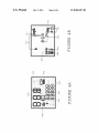
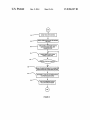
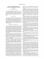
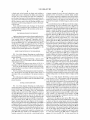
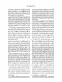
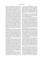
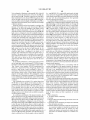
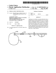
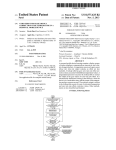
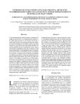
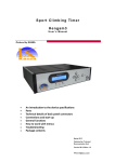
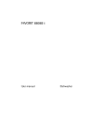
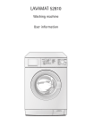
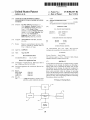
USOO8906307B2
(12) United States Patent
(10) Patent No.:
Andrews et a].
(54)
(45) Date of Patent:
APPARATUS FOR PROVIDING POWER
(58)
Field of Classi?cation Search
SYSTEMS
USPC
_
....................................................... .. 422/681
See application ?le for complete search history.
Inventors: Tae Wan Andrews, San D1ego, CA
(US); Stephen C. Bubrick, Orinda, CA
(US); Sheilah S. Estoesta, Mountain
View, CA (US); Brad D. Etter,
(56)
References Cited
U.S. PATENT DOCUMENTS
3 930 493 A
1/1976 W_11_
Alameda, CA (US); Hyoung Yoon Park,
Duluth, GA (US); Gene Ming Pon, San
’
Jose, CA (Us); Christopher“
r
1 lamson
4,018,547 A
Reggiardo, Castro Valley, CA (US);
Heber Saravia, Daly City, CA (US)
4/1977 Rogen
(continued)
FOREIGN PATENT DOCUMENTS
(73) Assignee: Abbott Diabetes Care Inc., Alameda,
CA (Us)
( * ) Notice:
Dec. 9, 2014
USPC ....................................................... .. 422/681
MANAGEMENT IN DATA COMMUNICATION
(75)
US 8,906,307 B2
EP
0455455
11/1991
EP
0878707
11/1998
Subject to any disclaimer, the term of this
(continued)
patent is extended or adjusted under 35
OTHER PUBLICATIONS
U.S.C. 154(b) by 117 days.
“An
(21)
Appl. No.: 12/859,081
(22) Filed:
Electrochemical
Aug. 18, 2010
(65)
Slow
Flow
Meter” http://goreocean.
washingtonedu/researchj slow ?ow meter.html, Feb. 10, 2005, 3.
(Continued)
Prior Publication Data
Us 2010/0312085 A1
Primary Examiner * Sam P Siefke
(74) Attorney, Agent, or Firm *Edward J. Baba; Shweta
Chandra; BoZicevic, Field & Francis LLP
Dec' 9’ 2010
Related US. Application Data
_
_
_
_
(57)
(63) JContmuatlon of app11catlon No. 10/861,626, ?led on
un. 4, 2004, now Pat. No. 8,071,028.
(60)
.
.
.
.
(51)
(2006-01)
(2006-01)
(2006-01)
19 Claims, 6 Drawing Sheets
(2013.01); A61B 2560/0209 (2013.01)
‘
V
USER
/ 101
/104
V
> GLUCOS E METER
TEST STRIP
DEVICE
/
.
.
glucose test strip, and corresponding methods of measuring
blood glucose meter is provided.
CPC ............. .. C12Q 1/54 (2013.01); A61B 5/]4532
102
.
umt dlsposed on the housmg, the dlsplay un1t 1nclud1ng a
display light source to illuminate the display unit, an input
unit disposed on the housing, the input unit con?gured to
provide input functions for the blood glucose meter, and a
power source provided Within the housing for providing
power to the blood glucose meter, Where the housing includes
a port integrated on said housing con?gured to receive a blood
Provisional application No. 60/478,436, ?led on Jun.
12, 2003.
Illt- ClG01N 33/00
C1 2Q 1/54
A613 5/145
(52) US. Cl.
ABSTRACT
A blood glucose meter having a compact housing, a display
103
/
A
V
EXTERNAL
COMPUTER
105
I
‘
‘
LANCING DEVICE
US 8,906,307 B2
Page 2
(56)
References Cited
U.S. PATENT DOCUMENTS
4,121,282
4,439,197
4,531,235
4,866,396
4,984,581
5,004,532
5,019,974
5,051,880
5,079,920
5,081,421
5,124,661
5,207,666
5,211,371
5,211,626
5,278,997
5,325,280
5,366,292
5,391,250
5,404,585
5,507,288
5,568,400
5,575,770
5,604,404
5,622,413
5,622,482
5,645,709
5,661,643
5,695,949
5,699,243
5,703,928
5,822,715
5,848,990
5,899,855
5,913,833
6,027,459
6,027,496
6,027,692
6,059,546
6,063,039
6,067,463
6,071,249
6,071,251
6,073,031
6,077,660
6,081,104
6,085,871
6,093,156
6,129,823
6,132,371
6,144,303
6,144,922
6,155,992
6,160,449
6,162,202
6,173,160
6,175,752
6,185,452
6,206,841
6,208,894
6,242,961
6,245,060
6,248,067
6,262,708
6,283,926
6,295,506
6,298,255
6,306,104
6,312,888
6,315,721
6,368,274
6,375,638
6,377,894
6,403,944
6,417,074
6,425,829
>D
10/1978
3/1984
7/1985
9/1989
1/1991
4/1991
5/1991
9/1991
1/1992
1/1992
6/1992
5/1993
5/1993
5/1993
1/1994
6/1994
11/1994
2/1995
4/1995
4/1996
10/1996
11/1996
2/1997
4/1997
4/1997
7/1997
8/1997
12/1997
12/1997
12/1997
10/1998
12/1998
5/1999
6/1999
2/2000
2/2000
2/2000
5/2000
5/2000
5/2000
6/2000
6/2000
6/2000
6/2000
6/2000
7/2000
7/2000
10/2000
10/2000
11/2000
11/2000
12/2000
12/2000
12/2000
1/2001
1/2001
2/2001
3/2001
3/2001
6/2001
6/2001
6/2001
7/2001
9/2001
9/2001
10/2001
10/2001
11/2001
11/2001
4/2002
4/2002
4/2002
6/2002
7/2002
7/2002
Ohsawa
Honda et al.
Brusen
Tamura
Stice
Hale
Beckers
Harm et al.
Whitehead et al.
Miller et al.
Zelin et al.
Idriss et al.
Coffee
Frank et al.
Martin
Tortola et al.
Voss
Cheney, II et al.
Vimpari et al.
Booker et al.
Stark et al.
Melsky et al.
Sahara
Kim et al.
Lee
Birch et al.
Blaker et al.
Galen et al.
Eckel et al.
Galloway et al.
Worthington et al.
Cirelli et al.
Brown
Elstrom et al.
Shain et al.
Loomis et al.
Galen et al.
Brenan et al.
Cunningham et al.
Jeng et al.
Cunningham et al.
Cunningham et al.
Helstab et al.
Wong et al.
Kern
Karamata
Cunningham et al.
Hughes et al.
Dempsey et al.
Federman
Douglas et al.
Henning et al.
Klomsdorf et al.
Sicurelli et al.
Liimatainen
Say et al.
Schulman et al.
Cunningham et al.
Schulman et al.
Liu et al.
Loomis et al.
Causey, III et al.
Chu
Cunningham et al.
Heinonen et al.
Cordero et al.
Cunningham et al.
Wong et al.
Schulman et al.
Van Antwerp et al.
Nason et al.
Deweese et al.
MacKenZie et al.
Kopley et al.
Julien
6,427,088
6,437,379
6,438,385
6,466,807
6,471,980
6,492,180
6,506,168
6,514,460
6,522,530
6,526,298
6,540,891
6,551,276
6,558,320
6,558,321
6,560,471
6,562,001
6,564,105
6,565,509
6,565,738
6,569,157
6,571,128
6,577,899
6,582,393
6,585,644
6,586,971
6,600,997
6,615,061
6,615,074
6,641,533
6,648,821
6,659,948
6,669,669
6,679,841
6,687,546
6,692,457
6,694,191
6,702,857
6,723,072
6,730,200
6,733,446
6,740,075
6,741,877
6,752,787
6,758,810
6,764,581
6,810,290
6,811,533
6,811,534
6,813,519
6,833,540
6,835,553
6,837,858
6,840,912
6,859,831
6,862,465
6,873,268
6,931,327
6,950,708
6,958,129
6,958,705
6,974,437
6,990,372
7,003,340
7,020,508
7,024,245
7,024,249
7,041,468
7,043,287
7,067,498
7,074,307
7,081,195
7,098,803
7,108,778
7,110,803
7,123,206
7,134,999
7,136,689
7,136,704
7,153,212
7/2002
8/2002
8/2002
10/2002
10/2002
12/2002
1/2003
2/2003
2/2003
2/2003
4/2003
4/2003
5/2003
5/2003
5/2003
5/2003
5/2003
5/2003
5/2003
5/2003
5/2003
6/2003
6/2003
7/2003
7/2003
7/2003
9/2003
9/2003
11/2003
11/2003
12/2003
12/2003
1/2004
2/2004
2/2004
2/2004
3/2004
4/2004
5/2004
5/2004
5/2004
5/2004
6/2004
7/2004
7/2004
10/2004
11/2004
11/2004
11/2004
12/2004
12/2004
1/2005
1/2005
2/2005
3/2005
3/2005
8/2005
9/2005
10/2005
10/2005
12/2005
1/2006
2/2006
3/2006
4/2006
4/2006
5/2006
5/2006
6/2006
7/2006
7/2006
8/2006
9/2006
9/2006
10/2006
11/2006
11/2006
11/2006
12/2006
Bowman, IV et al.
Kopley et al.
Heinonen et al.
Dobson et al.
Sirhan et al.
Brown et al.
Fathallah et al.
Fendrock
Bang
Khalil et al.
Stewart et al.
Mann et al.
Causey, III et al.
Bird et al.
Heller et al.
Lebel et al.
Starkweather et al.
Say et al.
Henning et al.
Shain et al.
Lebel et al.
Lebel et al.
Sage, Jr.
Lebel et al.
Naffziger et al.
Deweese et al.
Khalil et al.
Mickle et al.
Causey, III et al.
Lebel et al.
Lebel et al.
Flaherty et al.
Bojan et al.
Lebel et al.
Flaherty
Lebel et al.
Brauker et al.
Flaherty et al.
Stewart et al.
Lebel et al.
Lebel et al.
Shults et al.
Causey, III et al.
Lebel et al.
Forrow et al.
Lebel et al.
Lebel et al.
Bowman, IV et al.
Lebel et al.
MacKenZie et al.
Han et al.
Cunningham et al.
Kloepfer et al.
Gelvin et al.
Shults et al.
Lebel et al.
Goode, Jr. et al.
Bowman IV et al.
Galen et al.
Lebel et al.
Lebel et al.
Perron et al.
Say et al.
Stirovic et al.
Lebel et al.
Wei sner et al.
Drucker et al.
Khalil et al.
Wolf et al.
Simpson et al.
Simpson et al.
Mann et al.
Simpson et al.
Shults et al.
Hess et al.
Brauker et al.
Shults et al.
Schulman
Karten et al.
US 8,906,307 B2
Page 3
(56)
References Cited
U_S_ PATENT DQCUMENTS
7 154 398 B2
12/2006 Chen et a1,
2006/0020191 A1
1/2006 Brister et a1.
2006/0020192
2006/0036139
2006/0036140
2006/0036141
1/2006
2/2006
2/2006
2/2006
A1
A1
A1
A1
Brister et a1.
Brister et a1.
Brister et a1.
Kamath et a1.
731862566 B2
3/2007 Qian
2006/0036142 A1
2/2006 BriSter et a1.
7 192 450 B2
3/2007 Brauker et 31‘
2006/0036143 A1
2/2006 Brister et a1.
7’202’734 B1
7’205’409 B2
7’225’535 B2
4/2007 Raab
4/2007 Pei et 31‘
6/2007 Feldman et 31‘
2006/0036144 A1
2006/0036145 A1
2006/0222566 A1
2/2006 BriSter et a1.
2/2006 BriSter et a1.
10/2006 Brauker et a1.
11/2006 Fennell
732262978 B2
6/2007 Tapsak et 31‘
2006/0247508 A1
7 258 666 B2
8/2007 Brown
2007/0016381 A1
1/2007 Kamath et a1.
732663400 B2
9/2007 Fine et 31‘
2007/0163880 A1
7/2007 WOO et a1.
7 276 029 B2
10/2007 Goode Jr‘ et 31‘
2007/0203966 A1
8/2007 Brauker et a1.
733102544 B2
12/2007 Brister’et 31‘
2007/0235331 A1
10/2007 Simpson et a1.
7,344,507 B2
3/2008 Briggs et a1. ................ .. 600/583
Zoos/0021666 A1
1/2008 Goode, Jr et al
7 364 592 B2
4/2008 Carr_Brende1 et 31‘
2008/0033254 A1
2/2008 Kamath et a1.
2008/0045824
2008/0064941
2008/0071156
2008/0083617
2008/0086042
2008/0086044
2/2008
3/2008
3/2008
4/2008
4/2008
4/2008
7’366’556
7’379’765
7’424’3 18
7’460’898
7’467’003
734713972
B2
B2
B2
B2
B2
B2
4/2008
5/2008
9/2008
@2008
@2008
12/2008
Brister et 31‘
Petisce et 31‘
Brister et 31‘
Brister et 31‘
Brister et 31‘
Rhodes et 31‘
A1
A1
A1
A1
A1
A1
Tapsak et a1.
Funderburk et a1.
BriSter et a1.
Simpson et a1.
BriSter et a1.
BriSter et a1.
7 494 465 B2
2/2009 Brister et al‘
2008/0086273 A1
4/2008 Shults et a1.
7’497’827 B2
7’519’408 B2
7’583’990 B2
3/2009 Brister et 31‘
4/2009 Rade et 31‘
9/2009 Goode Jr‘ et 31‘
2008/0108942 A1
2008/0146900 A1
2008/0183061 A1
5/2008 BriSter et a1.
6/2008 Andrews et a1.
7/2008 Goode et a1.
7’591’801 B2
9/2009 Braukér et 31‘
2008/0183399 A1
7/2008 Goode et a1.
7’599’726 B2
10/2009 Goode Jr‘ et 31‘
2008/0188731 A1
8/2008 BriSter et a1.
7’613’491 B2
11/2009 Boock’et 31‘
2008/0189051 A1
8/2008 Goode et a1.
7’615’007
736322228
2001/0023095
2001/0024864
B2
B2
A1
A1
11/2009
12/2009
9/2001
9/2001
Shults et 31‘
Brauker et 31‘
Kopley et al‘
Kopley et al‘
2008/0194935
2008/0194936
2008/0194937
2008/0194938
A1
A1
A1
A1
8/2008
8/2008
8/2008
8/2008
BriSter et a1.
Goode et a1.
G0_0de et a1.
anter et a1.
2002/0118090
2002/0193679
2003/0023317
2003/0032874
2003/0060765
2003/0078560
A1
A1
A1
A1
A1
A1
8/2002
12/2002
1/2003
2/2003
3/2003
4/2003
Park et al‘
2008/0195232
Zoos/0195967
Zoos/0197024
2008/0200788
2008/0200789
Zoos/0200791
A1
8/2008 Carr-Brendel et a1.
Malave et a1.
Brauker et a1.
Rhodes et 31‘
Campbell et a1,
Miller et a1.
A1
A1
A1
A1
A1
8/2008
8/2008
8/2008
8/2008
8/2008
Goode et al
SlmPSOIl er al~
Brister et a1.
Brister et a1.
Simpson er al~
2003/0107487
2003/0198558
2003/0212346
2003/0217966
2004/0011671
2004/0019321
2004/0045879
2004/0064133
2004/0132220
2004/0133092
2004/0152622
2004/0186362
2004/0186365
2004/0199059
2005/0031689
2005/0038680
2005/0043598
2005/0053365
2005/0065464
Zoos/0090607
2005/0112169
2005/0143635
2005/0176136
Zoos/0182306
2005/0187720
A1
A1
A1
A1
A1
A1
A1
A1
A1
A1
A1
A1
A1
A1
A1
A1
A1
A1
A1
Al
A1
A1
A1
Al
A1
6/2003
10/2003
11/2003
11/2003
1/2004
1/2004
3/2004
4/2004
7/2004
7/2004
8/2004
9/2004
9/2004
10/2004
2/2005
2/2005
2/2005
3/2005
3/2005
4/2005
5/2005
6/2005
8/2005
8/2005
8/2005
Korman et 31‘
Nason et 31‘
Yuzhakov et a1.
Tapsak et al‘
Shults et a1,
Sage et a1,
shuns et al‘
Miller et a1,
Fish
Kain
Keith et a1,
Brauker et 31‘
Yin et a1,
Brauker et 31‘
Shults et a1,
McMahon
Goode, Jr. et a1.
Adams et a1,
Talbot et a1,
Tapsak et al‘
Brauker et 31‘
Kamath et al‘
Burd et al‘
Sloan
Goode Jr‘ et 31‘
2008/0208025
2008/0214915
Zoos/0214918
2008/0228051
2008/0228054
2008/0242961
2008/0262469
2008/0275313
2008/0287764
2008/0287765
2008/0287766
2008/0296155
2008/0306368
2008/0306434
2008/0306435
2008/0306444
2009/0012379
2009/0018424
2009/0030294
2009/0036758
2009/0036763
2009/0043181
2009/0043182
2009/0043525
2009/0043541
A1
A1
A1
A1
A1
A1
A1
A1
A1
A1
A1
A1
A1
A1
A1
A1
A1
A1
A1
A1
A1
A1
A1
A1
A1
8/2008
9/2008
9/2008
9/2008
9/2008
10/2008
10/2008
11/2008
11/2008
11/2008
11/2008
12/2008
12/2008
12/2008
12/2008
12/2008
1/2009
1/2009
1/2009
2/2009
2/2009
2/2009
2/2009
2/2009
2/2009
Shults et a1.
Brister et a1.
anter et al~
Shults et a1.
Shults et a1.
Brister et a1.
Brister et a1.
Brister et a1.
Rasdal et a1.
Rasdal et a1.
Rasdal et a1.
Shults et a1.
Goode et a1.
Dobbles et a1.
Kamath et a1.
Brister et a1.
Goode et al~
Kamath et a1.
Petisce et a1.
Brauker et a1.
Brauker et a1.
Brauker et a1.
Brauker et a1.
Brauker et a1.
Brauker et a1.
2005/0192557
Zoos/0235732
2005/0245795
2005/0245799
2005/0249606
2006/0001551
2006/0015020
2006/0016700
2006/0019327
2006/0020186
2006/0020187
2006/0020188
2006/0020189
2006/0020190
A1
A1
A1
A1
A1
A1
A1
A1
A1
A1
A1
A1
A1
A1
9/2005
10/2005
11/2005
11/2005
11/2005
1/2006
1/2006
1/2006
1/2006
1/2006
1/2006
1/2006
1/2006
1/2006
Braukér et 31‘
Rush
Goode Jr‘ et 31‘
Braukér et 31‘
Rush
Kraft et 31,
Neale et a1.
Brister et a1.
Brister et a1.
Brister et a1.
Brister et a1.
Kamath et a1.
Brister et a1.
Kamath et a1.
2009/0043542
2009/0045055
2009/0062633
2009/0062635
2009/0076356
2009/0076360
2009/0076361
2009/0099436
2009/0124877
2009/0124878
2009/0124879
2009/0124964
2009/0131768
2009/0131769
A1
A1
A1
A1
A1
A1
A1
A1
A1
A1
A1
A1
A1
A1
2/2009
2/2009
3/2009
3/2009
3/2009
3/2009
3/2009
4/2009
5/2009
5/2009
5/2009
5/2009
5/2009
5/2009
Brauker et a1.
Rhodes et a1.
Brauker et a1.
Brauker et a1.
Simpson et a1.
Brister et a1.
Kamath et a1.
Brister et a1.
Goode, Jr. et a1.
Goode et a1.
Brister et a1.
Leach et a1.
Simpson et a1.
Leach et a1.
US 8,906,307 B2
Page 4
(56)
2009/0131776
2009/0131777
2009/0137886
2009/0137887
2009/0143659
2009/0143660
2009/0156919
References Cited
2009/0299155 A1
12/2009 Yang et al.
US, PATENT DOCUMENTS
2009/0299156 A1
2009/0299162 A1
2009/0299276 A1
12/2009 Simpson et al.
12/2009 Brauker et al.
12/2009 Brauker et al.
A1
A1
5/2009 Simpson et al.
5/2009 Simpson et a1.
2009/0156924
2009/0163790
2009/0163791
2009/0178459
2009/0182217
2009/0192366
2009/0192380
2009/0192722
A1
A1
A1
A1
A1
A1
A1
A1
A1
A1
A1
A1
A1
5/2009
5/2009
6/2009
6/2009
6/2009
6/2009
6/2009
6/2009
7/2009
7/2009
7/2009
7/2009
7/2009
2009/0192745
2009/0192751
2009/0203981
2009/0204341
2009/0216103
2009/0240120
A1
A1
A1
A1
A1
A1
7/2009 Kamath et al.
7/2009 Kamath et al.
8/2009 Brauker et 31‘
Shariati et al.
Shariati et al.
Li et al.
Brister et al.
Brister et al.
Shariati et al.
Brister et al.
Brister et al.
Li et al.
Li et al.
Mensinger et al.
Shariati et al.
Shariati et al.
8/2009 Brauker et 31‘
8/2009 Brister et al.
9/2009 MenSingeT et al~
FOREIGN PATENT DOCUMENTS
EP
EP
JP
JP
W0
W0
W0
W0
W0
W0
W0
0543916
1130638
2001177423
2001056673
WO 02084860
WO 2004028337
WO 2005101994
WO 2006079114
WO 2006110913
WO 2006113408
WO 2006113521
7/2001
9/2001
6/2001
11/2001
10/2002
4/2004
11/2005
7/2006
10/2006
10/2006
10/2006
Barbosa, R. M. (1996) “Electrochemical Studies of Zinc in Zinc
Insulin Solution”, Journal of the Royal Society of Chemistry.
CAPLUS Abstract. Analyst 121(12): 1789-1793.
Bard, A. J ., et a1. (2001) “Methods Involving Forced Convectioni
2009/0240128 A1
9/2009 Mensinger et al~
Hydrodynamic Methods”, Electrochemical MetliodsiFundamen
2009/0240193 A1
9/2009 Mensinger et al.
tals and Applications. 331367‘
2009/0242399
A1
10/2009
Kamath et al.
.
.
“
.
.
,,
2009/0242425 A1
10/2009 Kamath et al‘
Kissinger, P. T. (1996) Introduction to Analog Instrumentation ,
2009/0247855 A1
10/2009 Boock et 31‘
Laboratory Techniques in Electroanalytical Chemistry, Second Edi
2009/0247856 A1
2009/0287073 A1
2009/0287074 A1
10/2009 Boock et a1.
11/2009 Boock et a1.
11/2009 Shults et al.
tion, Revised and Expanded, Jan 165-194
* cited by examiner
US. Patent
Dec. 9, 2014
US 8,906,307 B2
Sheet 1 0f 6
02N6US(M1D
A,m w:
wKOhDJmUE
\lmi
l!
5E.wWa
\‘New
or
mFMDQE
US. Patent
Dec. 9, 2014
Sheet 3 0f6
US 8,906,307 B2
301
307
302
303 —V@
305
304
‘6'
306
309
308
310
FIGURE 3
US. Patent
Dec. 9, 2014
US 8,906,307 B2
Sheet 4 0f 6
41
413
F4IGUBRE
410
414
4089
404
405
302
406
.vEDEE 403
401
402
F4IGUARE
US. Patent
Dec. 9, 2014
Sheet 5 0f6
DETECT TEST STRIP INSERTION
501
M VERIFY INSERTED TEST STRIP AND PERFORM
5°?
SELF TEST
I
TURN ON DISPLAY AND PROMPT USER TO
5°3 A
ENTER OR CONFIRM TEST STRIP
CALIBRATION coDE
<-——-———Mo
504
r
PROMPT USER TO APPLY BLOOD
SAMPLE T0 TEST STRIP
$05
AMPLE DETECTION COMPLETE?
YES
sue
'
—/\ SIGNAL TO USER THAT sAMPLE FILL ls COMPLETE
AND GLUCOSE LEVEL IS now BEING ANALYZED
I
507
DETERMINE GLUCOSE VALUE CORRESPONDING
TO DETECTED BLOOD SAMPLE
sea
7
/\ DISPLAY DETERMINED GLUCOSE
VALUE AND STORE m MEMORY
FIGURE 5
US 8,906,307 B2
US. Patent
Dec. 9, 2014
Sheet 6 0f6
US 8,906,307 B2
10 %
50% CDyuctlye
%\A
0
10 %
50%4
0%
6FIGURE
US 8,906,307 B2
1
2
APPARATUS FOR PROVIDING POWER
MANAGEMENT IN DATA COMMUNICATION
SYSTEMS
of light intensity by, for example, adjusting the duty cycle and
the period during which the light source is con?gured to be
RELATED APPLICATION
Additionally, in accordance with a further aspect of the
invention, the blood glucose meter may include a numerically
displayed clock with a date display which may be visible
turned on.
when the meter is not in use. Moreover, the clock feature in
yet a further embodiment of the present invention may
This application claims priority under 35 USC §ll9 to
Provisional Patent Application No. 60/478,436 ?led on Jun.
include an alarm which would allow the users to set alarm
12, 2003, entitled “Method and Apparatus for Providing
Power Management in Data Communication Systems”, the
disclosure of which is incorporated herein by reference for all
reminder for performing blood glucose level testing, where
purposes.
auditory alarm, a visual alarm alert, and a vibration alert
mode.
Indeed, a blood glucose meter in accordance with one
embodiment of the present invention includes a compact
housing for a blood glucose meter, a display unit disposed on
the alarm feature may include one or a combination of an
BACKGROUND
The present invention relates to data monitoring systems.
More speci?cally, the present invention relates to portable
the housing, the display unit con?gured to display informa
tion related to the blood glucose meter, an input unit disposed
analyte monitoring systems. More speci?cally, the present
on the housing, the input unit con?gured to provide input
invention relates to a compact, blood glucose meter for use in
a glucose monitoring system to self-monitor glucose level in
20
provided within the housing for providing power to the blood
glucose meter.
The display unit may include one of a liquid crystal display
whole blood, as an aid to disease management, and also by
healthcare professionals as an aid to monitor the effectiveness
of diabetes treatment.
SUMMARY OF THE INVENTION
25
The market for glucose monitoring systems in the United
The light source in one embodiment may be con?gured to
30
length of approximately 570 nanometers.
In one embodiment, the light source may include a light
emitting diode (LED), and more speci?cally, a yellow-green
35
glucose levels.
cose test strip.
40
device to be carried around or used and operated by the
patients, especially children.
In view of the foregoing, in accordance with the various
embodiments of the present invention, there is provided a
blood glucose meter which is designed to be substantially
more compact than presently available commercial blood
glucose meters, which con?guration that is much more ame
nable to usage and portage by younger diabetic patients such
as children.
LED.
In a further embodiment, the housing may include a port
integrated on the housing con?gured to receive a blood glu
While miniaturization has been a factor of recent designs in
the glucose monitoring systems and the glucose meters, the
physical constraints of the components of such systems have
established a certain size limitation. As such, the larger and
bulkier the device, the less desirable and convenient for the
be pulsed at a frequency greater than 60-100 Hertz. Moreover,
the light source may further con?gured to have a peak wave
glucose using glucose monitoring systems. One group of such
rapidly increasing segment of the population is children with
diabetic conditions who are advised to monitor their blood
(LCD), a touch sensitive screen, and a plasma display unit.
The display unit may also include a light source to illumi
nate the display unit, where the light source may be con?g
ured to provide a backlight function and a ?ashlight function
of the display unit.
States as well as globally is rapidly increasing, as better health
education and early detection of diabetic conditions through
regular check ups have increased the percentage of the dia
betic population who undertake the task of monitoring their
diet and daily activities based on the detected level of blood
functions for the blood glucose meter, and a power source
The port may include a light source that may be con?gured
to substantially illuminate the port to assist in the insertion
and/or removal of the blood glucose test strip.
In yet another embodiment, the display unit may be con
?gured to illuminate upon detection of a blood glucose test
strip insertion into the port. Further, the display unit may be
45
50
con?gured to remain illuminated until the test strip is
removed from the port.
The input unit in one embodiment may include an on/off
switch.
A blood glucose meter in accordance with another embodi
ment includes a compact housing for a blood glucose meter,
non-daylight times and so on, as well as a light source to guide
a display unit disposed on the housing, the display unit
including a display light source to illuminate the display unit,
an input unit disposed on the housing, the input unit con?g
ured to provide input functions for the blood glucose meter,
and a power source provided within the housing for providing
power to the blood glucose meter, where the housing includes
the insertion and removal of the test strip, which may include
the usage of a light emitting diode. Indeed, as the light source
glucose test strip.
More speci?cally, in one aspect of the invention, the blood
glucose meter is con?gured to include a LCD backlight and a
?ashlight features which will assist the patient in reading the
metered glucose level in low-light testing areas such as in
theaters, low ambient light restaurants, areas, outdoors during
55
a port integrated on said housing con?gured to receive a blood
(e.g., the LED) may be pulsed and still display substantially
the same light output as one which is turned on in steady state,
The port in one embodiment may include a port light
60
the battery life of the glucose meter device may be prolonged
since the pulsed LED light source requires signi?cantly less
power (and thus draining the battery at a much slower rate)
source, the port light source con?gured to substantially illu
minate the port to assist in the insertion and/or removal of the
blood glucose test strip.
Additionally, in an alternate embodiment, the port light
unit of the glucose meter device may be con?gured to control
source may be integrated with the display light source.
A method of measuring blood glucose level in accordance
with yet another embodiment of the present invention
the switching on and off of the light source as well as the level
includes the steps of providing a compact housing, disposing
than when the LED light source is maintained at the on
position. Indeed, in one embodiment, the central processing
65
US 8,906,307 B2
3
4
a display unit on the housing, the display unit including a
or laptop computer for use by the user’s physician or care
display light source to illuminate the display unit, disposing
an input unit on the housing, the input unit con?gured to
provider (or the user herself), a personal digital assistant
(PDA) which is operatively con?gured to store and/or further,
provide input functions for the blood glucose meter, provid
to communicate with a data network to transmit and receive
ing a power source within the housing for providing power to
patient data related to the glucose level detected from the
collected blood sample, for further diagnosis, analysis and the
the blood glucose meter, where the housing includes a port
integrated on said housing con?gured to receive a blood glu
like.
In one embodiment, the user 101 may provide the con?gu
ration parameters as well as calibration code to the glucose
meter device 103, while the glucose meter device 103 may be
con?gured to output signal prompts to the user 101 such as to
indicate a sample ?ll signal and a sample result signal, and
cose test strip.
These and other features and advantages of the present
invention will be understood upon consideration of the fol
lowing detailed description of the invention and the accom
panying drawings.
further, to output display the resulting measured blood glu
cose level from the sampled blood from the user 101. Fur
INCORPORATION BY REFERENCE
thermore, after the user 101 is lanced with the lancing device
104 to generate suf?cient amount of sample blood, the test
Applicants herein incorporate by reference application Ser.
strip 102 is provided in contact thereto (i.e., to the sample
blood) while the test strip 102 is operatively coupled to the
No. 09/434,026 ?led Nov. 4, 1999 entitled “Small Volume In
Vitro Analyte Sensor and Methods”, application Ser. No.
09/753,746 ?led on J an. 2, 2001 entitled “Analyte Monitoring
Device and Methods of Use”, and Application Nos. 60/437,
374 ?led Dec. 31, 2002 and application Ser. No. 10/745,878
20
glucose meter device 103. In this manner, the glucose meter
device 103 may in one embodiment be con?gured to alert the
user that the amount of blood sample on the test strip 102 is
suf?cient to determine the corresponding blood glucose level.
In one aspect of the present invention, the glucose meter
?led Dec. 26, 2003 both entitled “Continuous Glucose Moni
toring System and Methods of Use”, each assigned to the
Assignee of the present application for all purposes.
device 103 may be con?gured to make clinical measurements
25
BRIEF DESCRIPTION OF THE DRAWINGS
of glucose in whole blood in the range for approximately 20
to 500 mg/dL. Furthermore, as discussed in further detail
below, the glucose meter device 103 may be con?gured to
FIG. 2 is a block diagram illustrating a glucose meter
device shown in FIG. 1 in accordance with one embodiment
include a display unit which is con?gured to operate as a user
interface to visually interact with the user 101 to prompt for
data input, or alternatively, to provide information to the user
101 corresponding to the user’s operation of one or more
functions of the glucose meter device 103. In one embodi
of the present invention;
ment, the display unit of the glucose meter device 103 may
FIG. 1 is a block diagram illustrating an overall glucose
monitoring system in accordance with one embodiment of the
present invention;
FIG. 3 illustrates the glucose meter device of FIG. 2 in
accordance with one embodiment of the present invention;
FIGS. 4A and 4B illustrate the display screen of the glu
30
include a LCD display screen which may further be con?g
35
Moreover, in a further embodiment of the present invention,
the display unit of the glucose meter device 103 may be
con?gured to include a backlight feature which would permit
cose meter device in accordance with one embodiment of the
present invention;
FIG. 5 is a ?owchart illustrating the procedure forperform
ing a blood glucose test using the glucose meter device in
accordance with one embodiment of the present invention;
and
40
FIG. 6 illustrates the output LED power level as a function
of the power state in accordance with one embodiment of the
present invention.
ured, in an alternate embodiment to include a touch-sensitive
pad so as to allow the user 101 to input data therethrough.
45
the user 101 to operate the glucose meter device 103 in a dark
ambient setting such as in a theater, outdoor at night, and the
like.
FIG. 2 is a block diagram illustrating a glucose meter
device shown in FIG. 1 in accordance with one embodiment
of the present invention. Referring to FIG. 2, the glucose
meter device 103 in accordance with one embodiment of the
present invention includes a central processing unit 206
DETAILED DESCRIPTION
FIG. 1 is a block diagram illustrating an overall glucose
monitoring system in accordance with one embodiment of the
operatively coupled to a digital data processing unit 204. The
central processing unit 206 is further operatively coupled to a
50
storage unit 207 which, in one embodiment, may include one
present invention. Referring to the Figure, the glucose moni
or more of a data storage unit, a random access memory unit
toring system 100 in accordance with one embodiment
and a read-only memory unit. As can be further seen from the
includes a glucose meter device 103 con?gured to receive a
Figure, the digital data processing unit 204 is further opera
tively coupled to an input/output (I/O) interface unit 205
which, in one embodiment, is con?gured to interface with the
test strip 102 which is used to collect the blood sample for
determining the blood glucose level of the user 101. The
lancing device 104 is used to draw the blood sample from the
55
external computer 105 (FIG. 1).
user 101 to be collected onto the test strip 102. In one embodi
ment, the lancing device 104 may be used on the user’s
?ngers, forearm, upper arm, hand, thigh or calf, for example.
Moreover, the glucose meter device 103 and the system 100 is
con?gured such that a very small blood sample size such as,
60
digital data processing of the detected and processed analog
signals received from the analog data processing unit 201 in
for example, approximately 0.3 microliter of sample blood, is
necessary to determine a corresponding blood glucose level.
As can be further seen from FIG. 1, the glucose meter
device 103 may be operatively coupled to an external com
Moreover, in the glucose meter device 103, there is pro
vided an analog data processing unit 201 which is con?gured
to detect and process analog signals and which is further
operatively coupled to the digital data processing unit 204 for
one embodiment of the present invention. Referring back to
65
FIG. 2, the analog data processing unit 201 of the glucose
meter device 103 is further con?gured to operatively couple
puter 105 which may include, in one embodiment, a server
to a test strip connector unit 202 which is con?gured to
terminal connected to a data network, a stand along desktop
engage with a test strip 102 (FIG. 1) when inserted into the
US 8,906,307 B2
5
6
glucose meter device 103. Thereafter, the analog data pro
brate and operate the glucose meter device 103. More spe
ci?cally, upon power up of the glucose meter device 103
cessing unit 201 as mentioned above is con?gured to detect
the signal level from the collected blood sample received
from the test strip 102 (FIG. 1) via the test strip connector unit
202, and to transmit that detected and analog processed data
to the digital data processing unit 204 for further data pro
when the power source such as the batteries, are placed in the
cessing.
ize the various aforementioned components of the glucose
meter device 103 to the necessary con?guration settings.
Upon successful completion of the power on/reset sequence,
the central processing unit 206 is then con?gured to enter the
glucose meter device 103 into a default operation mode (for
example, the clock mode) as discussed in further detail below.
More speci?cally, in one embodiment, the central processing
respective section of the device housing, under the control of
the central processing unit 206, the glucose meter device 103
is con?gured to perform a power on/reset sequence to initial
Referring yet again to FIG. 2, there is also shown a user
interface unit 203 provided to the glucose meter device 103.
As can be seen, the user interface unit 203 is operatively
coupled to the user 101 (FIG. 1) to receive input data or
instructions therefrom, or alternatively, to output the pro
cessed and/or generated information to the user 101. More
speci?cally, in accordance with one embodiment of the
unit 206 is con?gured to access the storage unit 207 to retrieve
the corresponding power on/reset sequence instruction set
present invention, the user interface unit 203 may include a
display unit, an input device such as an input keypad, or any
from the storage unit 207 (for example, in the ROM portion
and/or the RAM portion thereof). Moreover, in one embodi
ment, the central processing unit 206 is con?gured to perform
other equivalent device which may provide substantially the
same functionality as the input device such as an input key
pad.
Additionally, the display unit of the user interface unit 203
may include an LCD display unit which is also capable of
20
providing backlighting so as to permit the user to view the
displayed information on the backlit display unit of the user
interface unit 203 in dark ambient settings. Moreover, in an
alternate embodiment of the present invention, the user inter
face unit 203 may also include a ?ashlight feature which,
upon activation by the user, is con?gured to emit a consistent
light beam to assist the user in the operation of the glucose
meter device 103 and/or the lancing device 104 in dark sur
roundings. Further, the ?ashlight feature may also be con?g
25
review mode. The default clock mode is con?gured in one
embodiment to display the time/ date information as con?g
ured by the user 101. The test mode includes operations for
the user to perform blood glucose measurements, the con?gu
30
con?gured, in one embodiment, to automatically turn off
after a predetermined period of time has elapsed. In this
reviewing of the glucose measurements stored in the meter
35
on.
Referring yet again to FIG. 2, the user interface unit 203 in
accordance with a further embodiment of the present inven
tion may include a speaker unit con?gured to output audio
ration mode includes functions for the user to select user
preferences for con?gurable parameters of the glucose meter
device 103, and the measurement log review mode allows
ured to include a timer function such that the ?ashlight is
manner, the power source for the glucose meter device 103
(FIG. 1) may be conserved in the cases where the user 101
leaves the ?ashlight feature on the glucose meter device 103
and complete the aforementioned power on/reset sequence
within approximately 500 mseconds.
In one aspect, the central processing unit 206 of the glucose
meter device 103 may be con?gured for operating the meter
device 103 in one of the following modes of operationithe
clock mode (the default mode discussed above), the test
mode, the con?guration mode, and the measurement log
40
signals. More speci?cally, in one aspect of the present inven
device 103.
In one embodiment, when the glucose meter device 103
enters a non-clock mode of operation, the meter device 103
may be con?gured to display a self-test screen that illumi
nates all segments of the display unit in the user interface unit
203 prior to operating in the selected mode of operation.
Moreover, the glucose meter device 103 may be con?gured to
exit all operation modes after exceeding a predetermined
tion, the user 101 may be alerted or reminded of one or more
time speci?c events or reminder such as the next time the user
period of non-activity/idle time (for example, 2 minutes) such
101 needs to take a blood glucose level measurement. Rather
example.
as no switch activity, test strip activity, or display activity, for
than relying solely upon the user’ s memory, the glucose meter
device 103 may be con?gured with an alarm feature opera
tively engaged with a timer function such that, in addition to
displaying the current time information on the display unit,
the glucose meter device 103 may be con?gured to generate
45
and output an audible sound for each speci?c event or
reminder which the user 101 has pre-programmed into the
glucose meter device 103. Moreover, in a further embodi
ment, the audible alarm output (or a series or audible tones as
50
may be selected by the user) may be simultaneously gener
ated with the backlight feature of the glucose meter device
Additionally, the central processing unit 206 of the glucose
meter device 103 is con?gured such that, upon detection that
there was a loss of power (for example, battery removal), the
internal date is set to the last recorded date, and in the case
where there is no valid recorded dates, the central processing
unit 206 is con?gured to set the internal date to a predeter
mined date such as J an. 1, 2002, for example. Likewise, upon
detection of the loss of power, the internal time in one
embodiment is reset to 12:00 am until a further time when the
user resets the internal time. Moreover, the blood sample test
103 such that for each of use, the user is able to view infor
mation displayed on the display unit of the user interface unit
data collected during the period of power loss is con?gured to
be ?agged with a “lost time” ?ag and the corresponding lost
power internal date and time discussed above. Upon re-appli
203 substantially immediately without the need to perform
cation of power to the glucose meter device 103, in one
55
embodiment, the user may be prompted (e. g., blinking signals
extra steps such as turning on the backlight function of the
glucose meter device 103. In the preferred embodiment, the
60
meter allows the user to set up to four separate alarms to go off
every 24 hours at a particular time to remind the user to test
her blood glucose level. Preferably, the volume of each alarm
may be set independently.
Referring back yet again to FIG. 2, in one embodiment of
the present invention, the central processing unit 206 is con
?gured to perform a plurality of functions to maintain, cali
displayed on the user interface unit 203) to reset the time and
date information in the default clock mode.
Referring still again to FIG. 2, in the test mode of operation
of the glucose meter device 103 in one embodiment, the
correct insertion of the test strip 102 (FIG. 1) engaged into the
65
test strip connector unit 202 of the meter device 103 is
detected, and upon removal of the test strip 102, the meter
device 103 is con?gured to enter the default operation mode.
US 8,906,307 B2
7
8
In this manner, the glucose meter device 103 may be con?g
ured to automatically enter into the test mode of operation
upon the correct insertion of the test strip 102. Alternatively,
the glucose meter device 103 may be con?gurable to enable
manual initiation of the test mode of operation (such as, for
shown, the glucose meter device 103 includes a housing 307
which substantially encases the meter device 103. In one
embodiment, the glucose meter device 103 may be physically
con?gured such that it is 3.12 inches in length, 2.25 inches in
width and 0.85 inches in height, with no more that l .4 ounces
example, by the user’s manual operation of the test mode
switch (not shown) of the meter device 103.
During the test mode of operation, if a faulty operation is
detected, the glucose meter device 103 is con?gured to gen
in weight with the batteries installed. Moreover, the material
used for the housing 307 may comprise plastic, metal, poly
mer, or a combination of any suitable material which provides
erate and output a corresponding respective message as such.
substantial physical integrity when subject to normal usage of
the meter device 103 including occasional dropping and other
Examples of such faulty operation includes, but not limited
physical impacts.
to, the detection of a used test strip, insuf?cient blood sample
on the test strip, incorrect insertion of the test strip into the test
strip connector unit 202 of the meter device 103, or when the
coulometer circuits are not ready for sample processing. The
Also shown in FIG. 3 is a data port 301 which corresponds
to the I/O interface unit 205 (FIG. 2), and is con?gured to
operatively couple to an external computer or data processing
device to transfer data collected and processed by the glucose
outputted message to the user alerting of the faulty operation
meter device 103. The data port 301 in one embodiment may
include one of a Universal Serial Bus (USB) port, an infrared
data communication port, a Bluetooth communication port,
may include an audible sound, a visual display, or a combi
nation of both.
Upon successfully collecting suf?cient blood sample for
processing from the user 101 (FIG. 1), the glucose meter
device 103 is con?gured to process the collected sample, and
to generate a corresponding blood glucose data for output
and a Wi-Fi wireless data communication port (for example,
20
display screen 302 which may be con?gured to display the
display to the user 101 on the user interface unit 203. The
blood glucose data may be, for example, displayed in units of
mg/dL or in units of mmol. Moreover, in one embodiment, the
meter device 103 may also be con?gured to display the time
and date information corresponding to the blood glucose level
test. Moreover, the central processing unit 206 is further
25
30
35
con?gurable parameters include the displayed date and time
change the test strip code, time and alarm settings, the output
display unit of the user interface unit 203 in the meter device
40
an average glucose level information based on a user selected
number of days such as 14-day or 30 day average of stored
results.
In the measurement log review mode of operation dis
cussed above, the glucose meter device 103 is con?gured to
sound options, date information, the measurement unit infor
mation, and for review of the stored sample results. Also, the
con?guration switch 304 may also be depressed to silence the
output of an alarm. Finally, the light switch 305 is con?gured
to control the operation of the backlight of the display screen
302, as well as the ?ashlight function of the meter device 103.
45
display a glucose summary (that is, the average glucose level
Referring yet again to FIG. 3, a test strip port 306 is addi
tionally provided on the housing 307 of the glucose meter
device 103, and is con?gured to receive the insertion of a test
strip 308. In one embodiment, the test strip port 306 substan
information) of stored results, as well as other parameters
such as the number of measurements incorporated into the
displayed average level, and a visual indication to the user that
the displayed data is the average glucose level information,
305. In one embodiment, the mode switch 303 may be oper
ated by the user to toggle between different operation modes
such as the test mode, and the clock mode (default), con?gu
ration mode, and the measurement log review mode, each
discussed above. The con?guration switch 304 may be con
?gured to, for example, mark a test result as control solution,
information, the alarm settings on the glucose meter device
103, the preferred display format for data display on the
1 03, the concentration unit of the generated glucose level, and
Also shown in FIG. 3 are three input switchesia mode
switch 303, the con?guration switch 304, and the light switch
operation, in one embodiment of the present invention, the
user 101 may select and input certain predetermined param
eters into the glucose meter device 103 to con?gure the meter
device 103 for subsequent use thereafter. For example, such
test results and other parameters and information such as time
and data information and the like. The display screen 302 in
one embodiment may include a built-in display backlight for
use in low-light conditions, and may be con?gured to auto
matically switch on in low-light settings for a predetermined
period of time (such as 1 minute, for example), or may be
con?gured for manual user operation.
con?gured to store the processed and displayed blood glucose
data in the storage unit 207.
Referring still to FIG. 2, in the con?guration mode of
IEEE 802.11 or its equivalents).
Referring back to FIG. 3, provided on the housing 307 is a
tially corresponds to the test strip connector unit 202 shown in
50
and not a speci?c sampled glucose level data. As will be
discussed in further detail below, the glucose meter device
103 may be con?gured to enter the measurement log review
mode of operation upon the operation of the mode switch (in
FIG. 2.Also provided on the test strip port 306 is a light source
such as a light emitting diode (LED) and the like which is
con?gured to switch on and off under the operation of, for
example, the light switch 305, or alternatively, in accordance
the user interface unit 203) while the meter device 103 is in
the default clock mode.
In one embodiment, the glucose meter device 103 may be
con?gured so that a “L0” is displayed for measured glucose
values which are below 20 mg/dL, and in contrast, a “HI” is
55
displayed when the measured glucose value exceeds 500
mg/dL. Furthermore, the meter device 1 03 may be con?gured
60
with a certain operations of the glucose meter device 103 such
as, for example, the detection of the test strip 308 at the
opening of the test strip port 306. As can be further seen, the
test strip 308 may include a top portion 309 and a bottom
portion 310 such that the top portion 309 is con?gured to be
inserted into the test strip port 306 of the glucose meter device
103, while the bottom portion 310 of the test strip 308 sub
stantially comprises the blood sample target areas for the user
to display the processed glucose level within approximately
to apply the blood sample or a control solution thereto. In one
15 seconds from the sampling of the corresponding blood for
samples below 200 mg/dL when measured at room tempera
ture and humidity.
embodiment, the test strip 308 is a Freestyle® Test Strip
FIG. 3 illustrates the glucose meter device of FIG. 2 in
accordance with one embodiment of the present invention. As
65
currently available from the assignee of the present applica
tion, TheraSense, Inc. of Alameda, Calif.
FIGS. 4A and 4B illustrate the display screen of the glu
cose meter device in accordance with one embodiment of the
US 8,906,307 B2
10
present invention. Referring to the Figures, the display screen
7-segment digits) of message area 403. As previously men
302 of the glucose meter device shown in FIG. 3 includes a
tioned, immediately after a blood glucose test is completed,
plurality of visual representation of display information. For
the numerical result is shown in the test result area 406. In this
example, as shown in FIG. 4A, the check owner’s manual
symbol 401 is displayed to alert the user 101 (FIG. 1) to refer
to the manual of the glucose meter device, and may be dis
played on the display screen 302 when, for example, the
meter device detects L0 or HI blood glucose level, out of
temperature range results, and low power state. The control
solution test result symbol 302 is displayed to alert the user
preferred embodiment, the date and time information are
displayed in a different area of display screen 302 from the
glucose test results, and with different sized digits (preferably
smaller as shown). Also, it is preferable that the test result area
406 be offset from the center of display screen 302, even more
preferably located in a comer of the display screen 302 as
shown.
In the manner described above, the display screen 302 of
the glucose meter device in accordance with one embodiment
that the user has marked a test result as a control solution test.
Referring back to FIG. 4A, the message area 403 of the
display screen 302 may be con?gured to display information
of the present invention may be con?gured to display infor
mation corresponding to the glucose tests and the processed
such as the date information, the time information, the num
ber of tests performed, and other information related to the
results in a easy and intuitive manner.
operation and function of the glucose meter device. There is
also provided in the display screen 302 a test result area 406
FIG. 5 is a ?owchart illustrating the procedure for perform
ing a blood glucose test using the glucose meter device in
which is con?gured to display the resulting glucose level
determined from the corresponding blood sample. Also
Referring to FIGS. 2 and 5, at step 501, the glucose meter
shown in FIG. 4A are a battery symbol 405 and a memory
accordance with one embodiment of the present invention.
20
mode symbol 404, where the battery symbol 405 is con?g
ured to be illuminated when the power supply level (e. g., the
battery level) is detected to be lower than the optimum oper
ating level, and to alert the user 101 (FIG. 1) to replace the
same. The memory mode symbol 404 on the other hand, is
25
con?gured to display to the user 101 (FIG. 1) that the test
result displayed in the rest result area 406 has been stored in
the memory (the storage unit 207 (FIG. 2)) of the glucose
meter device. In one embodiment, the memory capacity of the
meter device may store up to approximately 250 blood glu
30
into the meter device.
After verifying the code number for the test strip, at step
cose test results.
Referring now to FIG. 4B, the display screen 302 may
further be con?gured to display a blood drop symbol and a
test strip symbol 414, which are con?gured to operate in
tandem to alert the user that the meter device is ready to apply
the blood sample or the control solution. Moreover, the unit
symbol 413 is con?gured to appear with the test result data
displayed in the test result area 406 of the display screen 302
when the blood sample has been successfully collected and a
corresponding glucose level has been determined based on
the collected blood sample. The date setup symbol 407 on the
display screen 302 may be displayed in the con?guration
mode when the user is setting the date information of the
glucose meter device.
As further shown, a check and set test strip code symbol
device detects the insertion of a test strip 102 in the test strip
connector unit 202 (FIG. 2). In response to the detection of the
test strip 102 insertion, the meter device 103 is powered on,
and at step 502, the inserted test strip is veri?ed and a self test
of the meter device is performed. More speci?cally, at step
502, a system check illumination brie?y lights up the entire
display screen 302 and the various data symbols and areas
included therein, and thereafter, in step 503 the user 101 is
prompted to input a code number which corresponds to the
calibration code number preassigned to the test strip inserted
504, the blood drop and test strip symbols 414 (FIG. 4B) are
displayed on the display screen 302 to prompt the user to
35
40
apply the blood sample to the test strip. When the blood
sample is in contact with the test strip, the test strip acts like
a sponge and pulls the blood into the strip through its edges.
Thereafter at step 505, it is determined whether the collected
blood sample amount is suf?cient to generate a corresponding
blood glucose level. If it is determined at step 505 that the
collected blood sample amount is not suf?cient to generate
the corresponding blood glucose level, then the procedure
returns to step 504 to prompt the user to further apply the
45
blood sample to the test strip.
On the other hand, if it is determined at step 505 that the
collected level of blood sample is suf?cient to generate the
408 is provided on the display screen 302 to alert the user to
corresponding blood glucose level, the user 101 (FIG. 1) is
check and set the test strip code, while the thermometer
symbol 409 is displayed on the display screen 302 when the
meter is operating in a temperature range that is beyond that
which will permit an accurate reading. A set of sound level
noti?ed as such in step 506 by an audible alert sound output
via the user interface 203 (e.g., through an output speaker),
50
symbols 410 are provided in one embodiment to indicate
whether the glucose meter device audible output alert mode is
at a predetermined setting (for example, high, low or off),
while the time set symbol 411 appears on the display screen
302 in the default clock mode when the user is setting the time
information on the glucose meter device. Finally, the data
average symbol 412 is con?gured to appear on the display
screen 302 with a glucose reading that is the average value of
the readings from the past 14 days, for example or any other
predetermined time period as may be established by the meter
store the generated glucose value in the storage unit 207 (FIG.
55
2).
60
?gured to output a single audible alert noti?cation when the
collected blood sample is suf?cient to generate the corre
sponding glucose level information, and to output a double
audible alert noti?cation when the glucose level information
has been determined and displayed on display screen 302.
Additionally, in one embodiment, the time and date informa
tion may also be displayed on the display screen 302 in
In one embodiment, the glucose meter device may be con
device as a default mode or by the user during calibration
stage of the glucose meter device.
In the preferred embodiment of the present invention, when
the meter 103 is not otherwise in use, the current date is
continuously displayed on the upper line (top row of ?ve
7-segment digits) of message area 403, and the current time is
continuously displayed on the lower line (bottom row of ?ve
and/or by visual display on the display screen 302 (FIG. 3).
The glucose meter device is then con?gured at step 507 to
determine the glucose value corresponding to the detected
blood sample, and thereafter at step 508, to display the result
ing glucose value on the display screen 302 (FIG. 3), and to
65
connection with the generated glucose level information.
In accordance with another embodiment, the glucose meter
device may be con?gured such that upon power on procedure,
the light source (e.g., an LED) at the test strip port 306 (FIG.
US 8,906,307 B2
11
12
3) is con?gured to illuminate at substantially 50% of the full
intensity to permit the introduction of the test strip 102 into
the test strip port 306. Thereafter, when the test strip 102 is
fully inserted into the test strip port 306 of the glucose meter
device, the light source at the test strip port 306, and alterna
tively, in addition to the backlight of the display screen 302, is
illuminated at the full intensity level to indicate blood sample
(i.e., step 505 (FIG. 5) is successfully performed), the light
source at the test strip port 306 is disabled, and the backlight
on the display screen 302 is once again illuminated so that the
user may view the corresponding glucose level generated
from the collected blood sample.
In a slightly different embodiment, pressing the light but
ton 305 powers on either the display backlight or the test strip
collection operation.
light, depending on what mode the meter is in. Pressing the
light button 305 in non-test modes powers on the display
When the collection of the blood sample is concluded, the
intensity of the light source at the test strip port 306 (and
backlight. The display backlight goes out when light button
alternatively, as well as the backlight of the display screen
305 is pressed again, or when the meter is inactive for 5
302) are reduced substantially to the 50% level again, and
when the test strip is removed from the test strip port 306, the
light source is con?gured to shut off completely. Indeed, as
test strip symbols appear on the display screen powers on the
seconds. Pressing the light button when the blood drop and
test strip light. The test strip light goes out when the light
the light source (e.g., the LED) may be pulsed and still display
substantially the same light output as one which is turned on
in steady state, the battery life of the glucose meter device
may be prolonged since the pulsed LED light source requires
signi?cantly less power (and thus draining the battery at a
much slower rate) than when the LED light source is main
tained at the on position. Indeed, in one embodiment, the
central processing unit 206 of the glucose meter device 103
may be con?gured to control the switching on and off of the
light source as well as the level of light intensity by, for
20
example, adjusting the duty cycle and the period during
25
which the light source is con?gured to be turned on. For
example, FIG. 6 illustrates the output LED power level as a
function of the power state in accordance with one embodi
ment of the present invention. As can be seen from the Figure,
50% duty cycle as shown on the X-axis corresponds to
approximately 80% of the output power level for the LED
light source.
In a preferred embodiment, a yellow/green LED is used for
the test strip light, such as part number LTl9209-40 manu
factured by Ledtech Electronics Corporation located in Hsin
Tien, Taiwan, or part number ZSG56W manufactured by
SunLED Co. located in Kowloon, Hong Kong. These LEDs
provide a light having a peak wavelength of about 575
nanometers, which has been found to provide optimal con
trast between various colors of blood against various skin
button 305 is pressed again, or the meter receives the correct
amount of blood for the test (i.e. the test strip is ?lled), or after
60 seconds of meter inactivity, or when the test strip is
removed from the meter. Thus, in this embodiment, the test
strip light cannot be activated unless there is a test strip
inserted in the test strip port. If either the test strip light or the
display backlight is used during the test mode, the backlight
preferably powers on to show the test results after the mea
surement is complete.
Preferably, the glucose meter is powered by two coin cell
batteries of a common size, such as CR2032. It is also pref
erable that one of the batteries is dedicated to powering the
test strip light and display backlight, and the other is dedi
cated to powering the meter’s processor and other functions.
It may also be desirable to allow the meter to be placed in a
30
35
“shelf mode” after ?nal testing at the factory such that even
with batteries inserted, nothing is shown on the display and
the processor is in an energy saving sleep mode until one of
the buttons is pressed or a test strip is inserted in the meter to
resume normal operation.
In the manner described above, in accordance with the
various embodiments of the present invention, the glucose
meter device 103 is con?gured such that it is simple, intuitive
and easy to use, permitting the user to perform the tests
relatively discreetly, and is also easily used by third parties
40
such as the user’s physician, nurse, care giver or family mem
pigments in low light conditions. More speci?cally, using a
yellow-green LED with peak wavelength of 570 nanometers
ber. Moreover, given the compact physical con?guration, the
glucose meter device 103 is substantially small, compact,
in one embodiment provided optional contrast between the
sleek and readily portable by the user.
various colors of blood against the skin pigments in low light
conditions.
45
Also, preferably, the test light LED is pulsed faster than
60-100 hertz so that it appears to the human eye that it is
continuously on without ?ickering, most preferably 3 or 7
khz. It has been discovered that a 10% duty cycle with the
LEDs speci?ed above provides the most desired balance
described in connection with speci?c preferred embodi
ments, it should be understood that the invention as claimed
50
between light intensity and battery power savings. A brighter
light output than this can be disruptive in certain low light
settings, such as a movie theater, and can inhibit inconspicu
Thereafter, the backlight is con?gured to turn off when the
blood drop and test strip symbols 414 are displayed in tandem
should not be unduly limited to such speci?c embodiments. It
is intended that the following claims de?ne the scope of the
present invention and that structures and methods within the
scope of these claims and their equivalents be covered
thereby.
ous blood glucose testing.
In an alternate embodiment of the present invention, the
glucose meter device may be con?gured such that the back
light on the display screen 302 is turned on when the test strip
102 is inserted into the test strip port 306 of the meter device.
Various other modi?cations and alterations in the structure
and method of operation of this invention will be apparent to
those skilled in the art without departing from the scope and
spirit of the invention. Although the invention has been
55
What is claimed is:
1. An analyte meter, comprising:
a housing;
a strip port disposed in the housing and sized to receive an
analyte test strip;
60
a processing unit for measuring an analyte level detected
to alert the user that the meter device is ready to apply the
blood sample or the control solution. At the same time that the
from the analyte test strip;
an interface unit that operatively couples the analyte meter
backlight is turned off, the light source at the test strip port
306 (e. g., the LED light source) is illuminated so that the user
may light up the test strip 102 and the sample acquisition site
to an external computer to transmit data related to the
on the user 101 if desired. Thereafter, when the meter device
detects a suf?cient level of blood sample on the test strip 102
analyte level detected from the analyte test strip,
65
wherein the interface unit operatively couples the ana
lyte meter to an external computer via a wireless con
nection;
US 8,906,307 B2
14
13
10. The analyte meter of claim 6, wherein the light source
a liquid crystal display (LCD) screen;
provides backlighting to the LCD.
a non-transitory memory comprising stored instructions
11. The analyte meter of claim 6, wherein the light source
is coupled to the housing on the same end as the strip port.
that cause the processing unit to
operate the analyte meter in a clock mode that displays
12. The analyte meter of claim 1, wherein the analyte meter
current time and/or date information on the LCD screen,
is a glucose meter.
a test mode for performance of analyte measurements, a
con?guration mode that enables user selection of con
13. The analyte meter of claim 1, measurement log review
mode allows reviewing of glucose measurements stored in
?guration preferences, and a measurement log review
mode that enables reviewing of stored analyte measure
ments, and
con?gure the analyte meter to automatically exit the clock
mode and enter the test mode upon receiving the analyte
the meter.
14. The analyte meter of claim 1, wherein when the meter
is in the measurement log review mode, the meter displays a
glucose summary of stored results, average glucose level
information, a number of measurements incorporated into the
displayed average level, or a visual indication to the user that
test strip in the strip port.
the displayed data is average glucose level information.
2. The analyte meter of claim 1, wherein the analyte meter
further comprises a mode switch to toggle between different
15. The analyte meter of claim 1, wherein the meter is
con?gured to enter the measurement log review mode upon
modes of operation.
operation of a mode switch in a user interface unit while the
meter is in the default clock mode.
3. The analyte meter of claim 1, wherein the analyte meter
exits all modes of operation after exceeding a predetermined
period of non-activity.
20
4. The analyte meter of claim 1, wherein the analyte meter
further comprises a speaker unit to output audio signals.
5. The analyte meter of claim 1, wherein the LCD displays
a memory mode symbol to indicate that data has been stored
in a memory unit of the analyte meter.
25
6. The analyte meter of claim 1, further comprising:
a light source coupled to the housing to illuminate the strip
port; and
mode, the con?guration mode, or the measurement log
a power source to provide power to the light source.
7. The analyte meter of claim 6, wherein the light source is
30
one or more LEDs.
8. The analyte meter of claim 6, wherein the analyte meter
pulses the light source at a predetermined frequency and
duty cycle is approximately 10%.
9. The analyte meter of claim 6, wherein the light source
illuminates the LCD.
review mode.
18. The analyte meter of claim 1, wherein the analyte meter
is con?gured to exit the test mode, the con?guration mode, or
the measurement log review mode after a predetermined
period of non-activity or idle time, and to enter the clock
mode following the exiting of the test mode, the con?guration
predetermined duty cycle, wherein the predetermined fre
quency is greater than 100 HZ, and wherein the predetermined
16. The analyte meter of claim 1, wherein the clock mode
is a default mode of operation for the analyte meter.
17. The analyte meter of claim 1, wherein the analyte meter
comprises a self-test screen that is displayed upon entry into
the test mode, the con?guration mode, or the measurement
log review mode; and wherein the self-test screen illuminates
all segments of the LCD screen prior to operation in the test
35
mode, or the measurement log review mode.
19. The analyte meter of claim 1, wherein the test mode is
automatically exited and the clock mode entered upon
removal of the analyte test strip from the strip port.
*
*
*
*
*