1
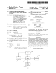
USOO8577633B2
(12) United States Patent
(10) Patent N0.:
Patel
(45) Date of Patent:
2008/0234935 A1
A
2009/0093984 Al :
2010/0307016 A1
PERSONAL MOBILE DEVICE
(75) Inventor:
_
_
KR
Notice:
Nov. 5, 2013
9/2008 Wolfet a1.
4/2009
6t ill. .................. .. 702/104
12/2010 Mayor et al. .................. .. 33/356
FOREIGN PATENT DOCUMENTS
Parln Patel, San Francisco, CA (US)
1020040062038
(73) Assignee: Apple 1116., Cupertino, CA (US)
(*)
US 8,577,633 B2
7/2004
OTHER PUBLICATIONS
Subject to any disclaimer, the term of this
patent is extended or adjusted under 35
U.S.C. 154(b) by 750 days.
“DSMZOO NMEA2000® Multi-Function Graphic Display”, User’s
Manual, Revision 1.7, Copyright© 2006 Maretron, LLC, Phoenix,
AZ, USA, Maretron Manual Part #: M000201, (p. i, pp. 29-30).
“SSC200 Solid State Rate/Gyro Compass”, User’s Manual, Revision
(21) App1_ NO; 12/794,531
1.7,Copyright© 2006,Maretron, LLC, PhoeniX,AZ, USA, Maretron
Manual Part #: M000401, 43 pages.
(22)
Filed:
Jun. 4, 2010
(65)
.
Prior PUblication Data
Dec. 8, 2011
Primary Examiner * Jonathan C Teixeira Moffat
us 2011/0301900 A1
Assistant Examiner * Hien V0
(74) Attorney, Agent, or Firm * Fish & Richardson PC.
(51) Int. Cl.
(57)
G06F 19/00
(52)
.
* cited by examiner
ABSTRACT
(201 1.01)
_
us CL
_
_
_
_
A personal mobile deV1ce housing contains a display screen,
USPC _______________ __ 702/72. 702 /9 4. 702/99. 702/104,
a Wireless telephony communications transceiver, and a bat
702/150. 73/137. 733/177. 733/497. 73/504181
’
’
’
’
tery charger interface. Atemperature sensor anda gyro sensor
3 2 4 /1 62’
Whose zero turn rate output contains an offset are also
USPC ~~~~~~~~~~~~~~~~ u 702/72, 94’ 99’ 104’ 1 50; 33/35 6;
rection values associated With different temperature values.A
(58) Field of Classi?cation Search
included. A lookup~table has gyro zero turn rate offset cor
73/1 37 1 77 497 50 4 18
'
’
'
’
’
programmed processor accesses the lookup table to correct
'
the output of the gyro sensor for zero turn rate offset. It is
see apphcanon ?le for complete searCh hlswry'
(56)
automatically determined, during in-the-?eld use, When the
References Cited
device is in a motionless state, and the output of the tempera
ture and gyro sensors are read. The read gyro output is written
U.S. PATENT DOCUMENTS
515271003 A
2002/0169553 A1
2003/0036847 A1
to the lookup table as part of a pair of associated temperature
and zero tum rate offset correction values. Other embodi
ments are also described and claimed.
6/1996 Diesel et 31~
11/2002 Perlmutter et al.
2/2003 Geier et a1.
13 Claims, 5 Drawing Sheets
START
OBTAIN OUTPUT DATA OF MOTION
SENSOR OVER A GIVEN TIME
INTERVAL
36
DOES THE
DATA INDICATE THE DEVICE
IS MOTIONLESS?
YES
PERFORM SAN ITV
CHECK ON THE READ
GVRO DATA - OK TO
WRITE TO LOOKUP
44
,J
NEW OFFSET CORRECTION VALUE
(ASSOCIATED WITH A NEW
TEMPERATURE VALUE]
WRITE AN OFFSET cORREcTIoN
VALUE To THE LOOKUP TABLE
(As PART OF A PAIR OF ASSOCIATED
TEMPERATURE AND ZRO CORRECTION
VALUES
UPDATED OFFSET CORRECTION
VALU ASSOCIATED WITH A
I,
PRE EXISTING TEMPERATURE
VE
YES
NEED TO UPDATE
OR FURTHER POPULATE
THE LOOKUF'
TABLE7
US. Patent
Nov. 5,2013
Sheet 1 0f5
US 8,577,633 B2
FIG.1
US. Patent
Nov. 5,2013
Sheet 3 0f5
ZRO
(deg/sec)
FIG. 3
US 8,577,633 B2
US. Patent
Nov. 5,2013
Sheet 4 0f5
US 8,577,633 B2
I START I
V
OBTAIN OUTPUT DATA OF MOTION
SENSOR OVER A GIVEN TIME
INTERVAL
34
DOES THE
DATA INDICATE THE DEVICE
IS MOTIONLESS?
NO
READ OUTPUT DATA OF
TEMPERATURE SENSOR
38
I
READ OUTPUT DATA OF
GYRO RATE SENSOR
40
I
PERFORM SANITY
CHECK ON THE READ
GYRO DATA - OK TO
WRITE TO LOOKUP
TABLE?
44
p]
NEW OFFSET CORRECTION VALUE
WRITE
VALUEAN
TOOFFSET
THE LOOKUP
CORRECTION
TABLE
(AS PART OF A PAIR OF ASSOCIATED
TEMPERATURE AND ZRO CORRECTION
VALUES)
I
UPDATED OFFSET CORRECHON
\_> VALUE (ASSOCIATED WITH A
PRE-EXISTING TEMPERATURE
46
VALUE; OVERWRITE OLD
CORRECTION VALUE)
YES
NEED TO UPDATE
OR FURTHER POPULATE
THE LOOKUP
TABLE?
FIG. 4
US. Patent
Nov. 5, 2013
US 8,577,633 B2
Sheet 5 0f 5
Oz
$3.25
.QEm
US 8,577,633 B2
1
2
GYRO ZERO TURN RATE OFFSET
CORRECTION OVER TEMPERATURE IN A
PERSONAL MOBILE DEVICE
In accordance with an embodiment of the invention, a
multi-function handheld device has a housing in which a gyro
sensor and a temperature sensor have been integrated at the
factory. The device also includes a programmed processor,
which accesses a lookup table to correct the output of the gyro
sensor for zero turn rate offset (ZRO). To populate the lookup
An embodiment of the invention relates to personal mobile
devices that include a gyroscope (gyro) whose zero turn rate
output may contain an error (also referred to as offset or bias),
table, the processor automatically determines, during in-the
or compensating) for the effect of such offset over the full
?eld use of the device or “normal use” by its end user, when
the device is in a motionless state. It then reads the output of
operating temperature range of the device. Other embodi
the temperature sensor as well as the output of the gyro sensor
ments are also described.
at that point, and writes the read gyro output value to the
lookup table as one of a pair of associated temperature and
and techniques for correcting (also referred to as calibrating
ZRO correction values. The lookup table need only have been
?lled partially at the factory, using an initial calibration or
testing process that can be performed relatively quickly on the
device, with very few temperature data points. Once the
device is in-the-?eld, however, the lookup table may be fur
ther developed or populated with many more temperature
BACKGROUND
Gyroscopes (or gyros, where the term is generically used
here to refer to angular rate, turn rate, or turn speed sensors)
have been suggested to be included in consumer electronics
personal mobile devices such as multi-function cellular
phones and smart phones. In such a multifunction handheld
portable device, the gyro may be used by applications that
measure heading changes (for example, in-the-?eld of navi
20
gation) or for measuring the rate of rotation as may be needed
by a video game application. The types of gyro that are
practical or suitable for use in such devices include micro
electromechanical system, MEMS, type vibratory gyros. A
25
MEMS vibratory gyro is particularly suitable for use in a
of the personal mobile device, again without requiring a sig
handheld device, because of its relatively small size, low
power consumption, suitability for high volume manufacture
and low cost. However, such a gyro may be particularly
sensitive to temperature, in that its turn rate output signal
(indicating the sensed rate at which the gyro package is rotat
30
ing about a given axis) exhibits signi?cant fabrication process
variation as well as temperature variation.
The gyro can be calibrated for zero rate offset during manu
facturing test, as follows. The gyro is kept motionless in a
35
temperature-controlled environment. Its output is then
sampled and recorded at different temperatures. This offset
data is then stored in a lookup table, together with the asso
ciated temperature values at which they were collected. The
table is then provided with the gyro to a system manufacturer
who integrates them into a personal mobile device. A calibra
ni?cant amount of time calibrating the gyro during manufac
turing test of the device.
A further aspect of the invention lies in performing a “san
ity check” for a newly read, ZRO value, before writing the
value to the lookup table. Since the process for populating the
lookup table is performed in-the-?eld, this may present unex
pected events (in contrast to a laboratory environment that is
well controlled during manufacturing test). A veri?cation
process is described that checks whether the read offset value
is signi?cantly different than a preexisting correction value
that is in an entry of the table whose temperature value is
suf?ciently close to the current temperature of the gyro. The
40
tion process in the mobile device can then periodically read a
temperature sensor that may be integrated with the gyro,
lookup the associated offset correction from the table, and
then apply the correction to the output of the gyro.
data points in a manner that is inconspicuous to its end user,
as the device is subjected to the wide range of temperatures
that are typically expected for such a device.
The in-the-?eld learning of ZRO corrections over tempera
ture may also be used to update pre-existing entries in the
lookup table. The ZRO of the gyro sensor may drift or vary
over time. The learning process may be used to update the
table so that gyro readings remain accurate throughout the life
preexisting entry may have been determined at the factory
during manufacturing test. If the read gyro output is signi?
cantly different than the preexisting value, then the read gyro
output is likely to be incorrect or corrupted. The corruption
may have occurred because of acoustic vibrations that cannot
45
be detected using the accelerometer but that nonetheless
interact with a mechanical gyro sensor in a way that corrupts
SUMMARY
the output of the gyro sensor. The sanity check serves to
prevent incorrect ZRO values in such a situation to be written
The one-time calibration process described above that can
be performed during the time of manufacturing test of a
multi-function handheld mobile device requires not just a
controlled temperature environment, but also a signi?cant
period of time to test each individual specimen of the device.
to the lookup table.
50
invention includes all systems and methods that can be prac
ticed from all suitable combinations of the various aspects
That is because a gyro that is integrated in such a device will
experience a relatively wide range of temperatures during
summarized above, as well as those disclosed in the Detailed
55
in-the-?eld use. Such devices are used in a wide range of
ambient temperatures, e.g. indoors and outdoors, in hot
weather and cold weather. In addition, the tight con?nes
inside the housing of such devices coupled with power-inten
sive functions being performed in them, such as music and
video playback, wireless communications, and video game
The above summary does not include an exhaustive list of
all aspects of the present invention. It is contemplated that the
Description below and particularly pointed out in the claims
?led with the application. Such combinations have particular
advantages not speci?cally recited in the above summary.
BRIEF DESCRIPTION OF THE DRAWINGS
60
The embodiments of the invention are illustrated by way of
gyro that is also inside the housing. However, the temperature
example and not by way of limitation in the ?gures of the
accompanying drawings in which like references indicate
range that is used for gyro calibration at the factory should be
similar elements. It should be noted that references to “an” or
processing, can cause a large swing in the temperature of the
as short as possible, so as not to spend an inordinate amount 65 “one” embodiment of the invention in this disclosure are not
of time just for testing a single function of such a multi
function device, in a high volume manufacture setting.
necessarily to the same embodiment, and they mean at least
one.
US 8,577,633 B2
4
3
For wireless telephony, a baseband processor 18 is
FIG. 1 shows a human user holding different types of a
multi-function handheld mobile device, namely a smart
included to perform speech coding and decoding functions
phone and a handheld tablet-like personal computer.
upon the uplink and downlink signals, respectively, in accor
dance with the speci?cations of a given protocol, e. g. cellular
GSM, cellular CDMA, wireless VOIP. A cellular transceiver
19 receives the coded uplink signal from the baseband pro
FIG. 2 is a block diagram of the constituent functional unit
blocks and hardware components in an example multi-func
tion handheld mobile device.
FIG. 3 is a graph of zero turn rate offset as a function of
cessor and up converts it to a carrier band before driving an
temperature, for a multi-axis gyro angular rate sensor.
FIG. 4 is an algorithm or process ?ow for populating and
updating a gyro zero turn rate offset correction lookup table.
FIG. 5 is an algorithm or process ?ow for performing a
sanity check on a read, gyro zero turn rate offset value.
antenna 20 with it, to reach a cellular network base station; it
also receives a downlink signal from the base station via the
antenna 20 and down converts the signal to baseband before
passing it to the baseband processor 18. A wireless local area
network transceiver 22 receives and transmits data packets
from a nearby wireless router or access point, using an
antenna 23.
DETAILED DESCRIPTION
Several embodiments of the invention with reference to the
appended drawings are now explained. While numerous
details are set forth, it is understood that some embodiments
of the invention may be practiced without these details. In
Power is provided to operate the components shown in
FIG. 2 by a battery 25 (generically used here to refer to a
rechargeable power source that may also include a recharge
able fuel cell). The battery 25 is charged or replenished by an
external power source such as a wall plug or automobile
20
other instances, well-known circuits, structures, and tech
niques have not been shown in detail so as not to obscure the
understanding of this description.
FIG. 1 shows two instances of a multi-function handheld
mobile device 2 (also referred to here as a personal mobile
25
29 and its associated interface 28 to be used for both power
transfer to recharge the battery 25 and for data I/O commu
device) held in the hands of an end user or owner of the device
2. In one instance, the device 2 is a smart phone or a multi
function cellular phone with several features typically avail
able in modern handheld wireless communication devices,
such as a touch screen interface, music and video ?le record
battery dc power adapter (not shown) that connects to a multi
pin docking connector 29 that is also integrated in the housing
of the device 2. The connector 29 and its associated charger
and I/O interface circuitry 28 may be in accordance with any
suitable computer peripheral speci?cation such as Universal
Serial Bus (USB). The USB protocol allows for the connector
nications. The latter includes docking functions, to synchro
30
nize user content in the device 2 with another computer device
owned by the user that may have substantially more data
ing and playback, digital camera, video games, and wireless
storage capacity, e.g. a desktop computer, a laptop/notebook
enabled applications such as voice over intemet protocol
computer.
telephony, electronic calendar, web browser, and email. In
The personal mobile device 2 presents a particularly chal
lenging task for dissipating su?icient heat that is produced as
a result of the various functions running inside its housing. A
another instance, the device 2 may be a larger, handheld
tablet-like computer such as an iPadTM device by Apple Inc.
35
FIG. 2 shows a functional unit block diagram and some
thermal management process is needed to make sure that
critical temperature points or hot spots inside and on the
constituent hardware components of the personal mobile
user is a touch sensitive display screen (referred to here as a
outside surface of the housing do not exceed their maximum
speci?cations; the process may be conducted with help from
a power management unit (PMU) 26. The PMU 26 is typi
cally implemented as a programmed processor, with associ
touch screen) 11. The housing may be essentially a solid
ated analog and digital conversion circuitry, analog signal
volume referred to as a candy bar or chocolate bar types as in
the iPhone device. An alternative is one that has a moveable,
multi-piece housing, such as a clamshell design, or one with
needed to control or communicate with other components of
device 2, e.g. as found in an iPhoneTM device by Apple Inc.
Although not shown, the device 2 has a housing in which the
primary mechanism for visual and tactile interaction with its
40
conditioning circuitry, and a data communications interface
45
the device 2 (for purposes of thermal management.) The PMU
a sliding, physical keypad as used by other cellular and
26 obtains temperature data (or temperature readings) from
mobile handset or smart phone manufacturers. The touch
screen 11 is used to display typical features of visual voice
multiple temperature sensors, as well as power data (sensed
or estimated power consumptions of certain power-hungry
components), and then processes that data to make decisions
mail, web browser, email, and digital camera view?nder, as
well as others, and to receive input from the user via virtual
buttons and touch commands.
For wireless telephony, which enables the user to receive
50
and place audio and/or video calls, downlink audio during a
call can be emitted from a speaker 13 (which may be an
earpiece speaker or receiver, or it may be a headset earphone).
Uplink audio includes the user’s speech, which is picked up
by a microphone 16 (e.g., mouthpiece microphone or headset
microphone). Conversion between analog domain and digital
domain for the speaker and microphone signals, in addition to
digital audio signal processing for different applications run
ning in the device 2, may be performed within audio codec 17.
A physical volume switch or button 15 may also be connected
to the codec. The codec 17 may be con?gured to operate in
different modes, e. g. to service a digital media player function
(such as an MP3 player that is playing back a music ?le that
is stored in the device 2), as well as a wireless telephony
function.
55
that affect power consumption activity, in order to maintain
speci?ed thermal levels or temperature constraints for the
device 2. For instance, if the back case of the device 2 is
becoming too hot, then the PMU may decide to take any one
or more several actions, including turning on a fan inside the
device 2 to more quickly pull the hot air from inside the device
2, lowering the maximum output power of ampli?ers used for
audio playback and cellular transmission, and lowering the
supply voltage and/ or main clock signal frequency of a large
processor. The PMU 26 may also include power supply cir
60
cuitry with various regulated voltage outputs for supplying
power to the components of the device 2. The PMU 26 may
also be tasked with the orderly powering down and powering
65
up the various components of the device 2, in response to
system reset or the main power on/off switch 27 being actu
ated by the user.
The device 2 also includes a motion sensor 7 which may
use an accelerometer to measure linear acceleration of the
US 8,577,633 B2
5
6
device 2 along a given axis. A gyro sensor 3 may use a MEMS
type mechanical vibratory gyroscope to measure turn rate or
The algorithm may begin with the programmed processor
automatically determining, during in-the-?eld use of the per
angular velocity of the device 2 about a given axis. A tem
sonal mobile device 2, that the device is in a motionless state.
perature sensor 5 may use a thermistor to measure tempera
This is depicted in blocks 34 and 36 where output data of the
ture of the gyro sensor 3. The temperature sensor 5 may be
integrated with the gyro sensor 3 on the same integrated
motion sensor 7 is obtained over a given time interval. For
example, samples from the output of an accelerometer may be
taken for several seconds, and if the average of these samples
circuit die or alternatively in the same integrated circuit pack
is less than a selected threshold, such as 2% of what represents
a motionless state (namely zero acceleration), then the data
age.
The user-level functions of the device 2 are implemented
under control of a processor 6 that has been programmed in
indicates that the device is motionless such that operation
may continue with reading the output of the temperature
accordance with instructions (code and data) stored in
sensor (block 38) and the output of the gyro turn rate sensor
(block 40). Note also that in blocks 38 and 34 as part of the
sensor readout operation, a smoothing function may be
memory 4. The processor 6 and memory 4 are generically
used here to refer any suitable combination of programmable
data processing components and data storage that conduct the
operations needed to implement the various functions of the
device. The processor 6 may be an applications processor
typically found in a smart phone, while the memory 4 may
refer to microelectronic, non-volatile random access
memory. An operating system may be stored in the memory 4,
applied to a short sequence of raw output values from the
sensors to obtain a single, representative value. For instance,
the actual output data that is evaluated or used in a subsequent
operation below may be an average of several samples taken
20
along with application programs speci?c to the various func
from the respective sensor, so as to smooth out the effects of
noise in instantaneous readings from the sensors, or to ensure
that the raw values are reasonably stable before using them.
tions of the device, which are to be run or executed by the
Next, skipping to operation 44, the read gyro output is
processor 6 to perform the various functions of the device 2.
written to the lookup table 9 as an offset correction value, as
For instance, there may be a telephony application that (when
launched, unsuspended, or brought to foreground) enables
part of a pair of associated temperature and ZRO correction
25
values. If the gyro output value is associated with a new
the user to “dial” a telephone number to initiate a telephone
temperature value, that is, one not previously existing in the
call using wireless VOIP or a cellular protocol and to “hang
up” on the call when ?nished.
As explained above, certain types of gyro sensors exhibit
strong variation in their ZRO with temperature, and thus need
table, then this is considered a new offset correction value and
is therefore written into a new entry (together with the tem
30
perature value that was read in block 38). On the other hand,
if the temperature value from block 38 matches a preexisting
ture range. FIG. 3 is a graph of ZRO as a function of expected
temperature value in the lookup table, then operation 44
essentially updates or overwrites the old ZRO correction
operating temperature range, for an example multi-axis
mechanical gyro. A corrected gyro reading can be obtained by
value of that entry in the table 9. The process then may repeat
with blocks 34-44, if there is a need to update or further
to be corrected across their full, expected operating tempera
subtracting the ZRO (that is speci?ed for the current gyro
temperature) from the current gyro output. The processor 6
35
populate the entries in the lookup table. For instance, the
process in FIG. 4 may be repeated each time a signi?cant
period of time has elapsed since the table 9 was deemed to be
may be programmed in accordance with a gyro ZRO correc
tor program module 8 (which may be stored in the memory 4),
complete, so as to ensure that any drifts or variations in the
to achieve such a result.
gyro sensor 3 are recaptured and corrected. The process may
Still referring to FIG. 2, the ZRO corrector 8 produces
corrected gyro readings as follows. Speci?cally, the proces
40
coverage for the full, expected operating temperature range of
sor 6 is programmed to read the outputs of the gyro sensor 3
and the temperature sensor 5 within a relatively short time
interval of each other, to determine gyro output at a particular
temperature. A lookup table 9 stored in the device 2, e. g. in the
the gyro sensor 3.
Still referring to FIG. 4, the programmed processor 6 may
45
block 42 is not necessary in all instances, it does help prevent
to ?nd a ZRO correction value associated with that tempera
ture. For example, as seen in FIG. 2, if the temperature sensor
5 shows 10.7+/—0.2 Celsius, then the ZRO correction value to
Ideally, lookup table 9 should be ?lled, as depicted in the
graph of FIG. 3, with temperature and ZRO values spanning
the entire expected operating temperature range of the gyro
and in suf?ciently ?ne granularity. However, as explained
below, this may not be practical at the time of manufacturing
also perform a sanity check on a read gyro output, before
deciding it is proper to write it to the lookup table as a new or
updated correction value (block 42). While the operation in
memory 4, is then accessed using the particular temperature,
be applied to the read gyro output is —3.0 degrees/ sec. The
corrected gyro output value may then be passed to an appli
cation that needs to know the current angular velocity of the
device 2 with good accuracy.
also be triggered when the table 9 does not yet have suf?cient
50
the table 9 from being populated with possibly corrupt values
or clearly incorrect values, especially since the process of
FIG. 4 is being performed in-the-?eld essentially inconspicu
ous to the end user, and thus may be subject to unexpected
events that could interfere with operation of the gyro sensor.
If the sanity check is cleared, then operation proceeds with
block 44 as described above, to write to the table 9. If, how
55
ever, the sanity check indicates a problem, then one or more of
the prior operations depicted in FIG. 4 should be repeated. For
instance, the output data of the gyro rate sensor may be
re-sampled through operation 40 and subjected to the sanity
test of the device 2. The device 2 may be shipped from its
factory with the lookup table 9 only partially ?lled. For
check again, to make sure that an incorrect offset correction
value is not written to the table 9. FIG. 5 shows an algorithm
example, the table 9 may initially contain only a few entries.
This allows the device 2 to pass through manufacturing test
more quickly. Once in-the-?eld, however, the ZRO corrector
8 may be used to advantageously program the processor 6 to
automatically populate the table 9 with many more entries,
while remaining inconspicuous to the end user. FIG. 4 shows
for the sanity check process.
Referring to FIG. 5, operation begins with block 52 in
which the read temperature and gyro outputs are compared to
preexisting temperature and offset correction pairs in the
table 9, to determine whether the read gyro output value is
signi?cantly different than a pre-existing correction value
an algorithm for such a process.
65
that is associated with a temperature value that is close to the
US 8,577,633 B2
7
8
read or current temperature. In one case, the comparison is
made with a preexisting pair that was written to the table 9 in
While certain embodiments have been described and
shown in the accompanying drawings, it is to be understood
that such embodiments are merely illustrative of and not
restrictive on the broad invention, and that the invention is not
limited to the speci?c constructions and arrangements shown
and described, since various other modi?cations may occur to
those of ordinary skill in the art. The description is thus to be
regarded as illustrative instead of limiting.
the factory. In other words, the in-the-?eld ZRO value is
checked against a ZRO correction value that was determined
at the factory during a manufacturing test, for example, that
was under well-controlled conditions (resulting in correct
gyro values).
If the in-the-?eld read gyro output is signi?cantly different
than a preexisting value from the table 9, then operation may
proceed with block 56 to determine whether the in-the-?eld
What is claimed is:
1. A personal mobile device comprising:
a multi-function handheld portable device housing in
which are integrated
read temperature and gyro outputs are close enough to an
estimated pair. This may be the situation where a new tem
perature is quite different than those already in the table 9. An
interpolation or extrapolation procedure may be performed to
a display screen;
a wireless communications transceiver;
determine an estimate of ZRO, for instance based on the
a battery charger interface;
preexisting data in the table 9, at the new temperature value.
If the read gyro output is not close enough to the estimated
value, then it is likely that the read gyro output is incorrect or
corrupted, in which case it should not be written to the lookup
table (block 58). This corresponds to the situation where for
a temperature sensor;
a movement sensor that generates data indicative of linear
movement of the device;
20
instance there may have been interference due to acoustic
vibrations in the device 2 that may not have been picked up by
the motion sensor 7, but that nevertheless interact with the
of containing an offset;
storage that stores a plurality of gyro zero turn rate offset
correction values associated a plurality of different tem
perature values, respectively; and
mechanical structure of the gyro sensor 3 to corrupt the gyro
output. It may be, for instance, that an acoustic vibration at
approximately the mechanical resonant frequency of the gyro
sensor 3 is occurring during readout, where such acoustic
vibrations may have been created by sound emitted from a
built-in speaker of the device 2. This could be the situation
where the user has placed the device 2 on a table (such that the
device is motionless), but has turned on the digital media
a gyro sensor having a zero turn rate output that is capable
25
a programmed processor to access the plurality of gyro
zero turn rate offset correction values for correcting an
output value of the gyro sensor for zero turn rate offset,
wherein the programmed processor is to
(a) automatically determine, during in-the-?eld use of the
30
personal mobile device, when the device is in a motion
less state by determining when output from the move
player application and the latter is playing music through the
ment sensor remains within a predetermined zero
built-in speakerphone or loudspeaker of the device 2. In that
situation, the process in FIG. 5 will detect that there is a
problem with the gyro zero rate output and therefore ignore
that value (for purposes of updating or writing to the lookup
threshold range for a predetermined time interval and (b)
based on gyro sensor output, add a zero turn rate offset
35
table).
correction value to the plurality of gyro zero turn rate
offset correction values as a part of a pair of associated
temperature and zero turn rate offset correction values.
Still referring to FIG. 5, and returning to operation 52, if the
2. The mobile device of claim 1 wherein the programmed
read temperature and gyro outputs are close enough to a
processor is to repeatedly perform (a)-(b), during in-the-?eld
preexisting temperature and offset correction value pair, then
40
use of the device, as the device encounters a range of different
a decision should be made next as to whether the preexisting
temperatures.
pair in the table 9 needs to be updated or overwritten (opera
tion 54). For instance, each entry in the lookup table may be
tagged with a date, such that if an entry is deemed to be old,
sensor and the gyro sensor are integrated in the same inte
then it should be updated or overwritten with a new reading.
In that case, the process in FIG. 5 indicates that the current or
3. The mobile device of claim 1 wherein the temperature
grated circuit package.
45
4. The mobile device of claim 1 wherein the movement
sensor is an accelerometer that generates data indicative of
linear acceleration of the device.
5. The mobile device of claim 1 wherein the programmed
read temperature and gyro output values should be written to
the lookup table (operation 59). The latter result is also
obtained if, returning now to operation 56, the read gyro
processor is to, prior to adding the offset correction value,
output is close enough to an estimated ZRO correction value.
50
Finally, there may be instances where the read temperature
and gyro outputs so closely match a preexisting pair in the
lookup table that there is no need to update the tableithis
result is indicated in operation 57.
As explained above, an embodiment of the invention may
55
determine if a read gyro output is within an expected range for
zero turn rate offset, ZRO, wherein the expected ZRO range is
computed based on one or more pre-existing pairs of associ
ated temperature and zero rate offset correction values in the
storage.
be a machine-readable medium (such as microelectronic
6. The mobile device of claim 1 wherein the programmed
processor is to, prior to adding the offset correction value,
memory) having stored thereon instructions, which program
estimate a zero rate offset correction value associated with a
one or more data processing components (generically
referred to here as a “processor”) to perform the gyro and
read output of the temperature sensor, based on pre-existing
data stored in the device that describes variation of the gyro
temperature sensor output data processing operations
described above, including reading from and writing to a
60
value.
ZRO correction lookup table. In other embodiments, some of
these operations might be performed by speci?c hardware
components that contain hardwired logic (e.g., dedicated
state machines). Those operations might alternatively be per
formed by any combination of programmed data processing
components and ?xed hardwired circuit components.
sensor’s zero rate offset over temperature, and then compares
a read gyro output to the estimated zero rate offset correction
7. A personal mobile device comprising:
a gyro sensor having a zero turn rate output that is capable
65
of containing an offset;
an accelerometer that generates data indicative of linear
acceleration of the device;
US 8,577,633 B2
10
10. A method for operating a personal mobile device hav
ing a gyro sensor, comprising:
correcting an output of a gyro sensor in the device by
accessing a plurality of storage entries some of which
were stored during manufacturing test of the device,
wherein each entry includes a different temperature
storage containing a plurality of initial entries that were
written to the storage during manufacturing test of the
device, wherein each entry includes a different tempera
ture value and a respective gyro zero turn rate offset
correction value; and
a programmed processor to access the storage to correct an
output of the gyro sensor for zero turn rate offset,
wherein the programmed processor is to add a plurality
of new entries to the storage during in-the-?elduse of the
device, wherein for each new entry the programmed
processor is to (a) automatically determine that the
device is in a motionless state by determining when
output from the accelerometer remains within a prede
value and a respective gyro zero turn rate offset correc
tion value; and
10
determining when output from a motion sensor
remains within a predetermined zero threshold range
for a predetermined time interval and
termined zero threshold range for a predetermined time
interval, and (b) based on gyro sensor output, add a zero
turn rate offset correction value to the storage as part of
a pair of associated temperature and zero turn rate offset
correction values included in the new entry.
adding a zero turn rate offset correct value, based on
gyro sensor output, as part of a pair of associated
temperature and zero turn rate offset correction values
included in the new entry.
11. The method of claim 10 further comprising:
8. The mobile device of claim 7 wherein the programmed
processor is to verify a gyro output before adding a zero turn
20
values stored in the table.
12. The method of claim 10 further comprising:
gyro output to a pre-existing offset correction value in the
storage.
9. The mobile device of claim 7 wherein the programmed
ture,
and wherein the programmed processor is to, before adding
a zero turn rate offset correction value to the storage
compare a gyro output to the estimated offset correction
value.
before adding a zero turn rate offset correction value, com
paring a gyro value to one or more offset correction
rate offset correction value to the storage, by comparing the
processor is to compute an estimated offset correction value
that is associated with the temperature of the gyro sensor,
based on previously stored data in the device that describes
variation of the gyro sensor’s zero rate offset over tempera
adding a plurality of new entries to the storage during
in-the-?eld use of the device, by, for each new entry,
determining that the device is in a motionless state by
25
before adding a zero turn rate offset correction value, com
paring a gyro value to an estimated offset correction
value that is associated with a determined temperature of
the gyro sensor.
30
13. The method of claim 12 further comprising:
computing the estimated offset correction value based on
previously stored data in the device that describes varia
tion of the gyro sensor’s zero rate offset over tempera
ture.
UNITED STATES PATENT AND TRADEMARK OFFICE
CERTIFICATE OF CORRECTION
PATENT N0.
: 8,577,633 B2
APPLICATION NO.
DATED
: 12/794531
: November 5, 2013
INVENTOR(S)
: Parin Patel
Page 1 of 1
It is certified that error appears in the above-identi?ed patent and that said Letters Patent is hereby corrected as shown below:
In the Claims
In Claim 1, column 8, line 23, after “associated” insert -- With --.
In Claim 9, column 9, line 31, delete “storage” and insert -- storage, --.
In Claim 10, column 10, line 15, delete “correct” and insert -- correction --.
Signed and Sealed this
Seventeenth Day of June, 2014
WMZ44L_
Michelle K. Lee
Deputy Director 0fthe United States Patent and Trademark O?ice