1
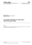
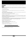
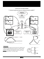
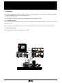
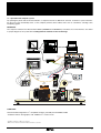
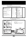
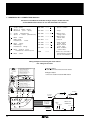
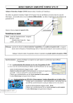
Réf. 2863 - 4.33 / a - 4.98 T I T I 00 11 22 33 44 55 66 77 88 n n 00 11 22 33 44 55 66 77 88 00 11 22 33 44 55 66 77 88 00 11 22 33 44 55 66 77 88 00 11 22 33 44 55 66 77 88 00 11 22 33 44 55 66 77 88 00 11 22 33 44 55 66 77 88 digital plotter Micro PC printer MODELEC 3 I ou I U ou U (A) P (w) (V) 20A Ie (A) 20A 2A 500V 2A 500V 50V 50V Moyenne du produit u.i Mean product u.i ANALOGUE ie i u OUTPUTS 0 2A 0 2A 20A 0 50V 500V POWER SUPPLY MODMECA 3 INTERFACE SAFETY CIRCUIT P (W) Offset 3000 W n (min-1) Etalonnage 2 000 min-1 50% Offset Etalonnage Calibration n manu T auto n auto T manu BRAKE 0 0 100% MANUEL e sent b t s u ual m n a m s user d Thi n e to the T (N.m) 6 000 min-1 Calibration 300 W FREIN 400V TRI + PE AUTO CONTROLE Réf. 2289 - O33 / a - 2.96 CAPTEUR DE COUPLE TORQUE TRANSDUCER O I brake coil Fiche Din BRAKE TERMINAL BLOCK U DT=60V à 1000 tr.min-1 U DT=20V à 1000 tr.min-1 to installation earth circuit solid-state transducer Powder brake Test motor MOTOR TERMINAL BLOCK DYNAMO TACHYMETRIQUE TACHO GENERATOR T.G TERMINAL BLOCK TRANSDUCER TERMINAL BLOCK FP10/15 O I solid-state transducer DT.L brake coil D.C. Tachogenerator MODMECA & MODELEC Modules for measuring electrical and mechanical values User manual MODELEC & MODMECA measurement modules CERTIFICATION according to the "Low Voltage" Directive : directive 73/23/EEC modified by 93/68/EEC, applicable from 1/01/97 Electromagnetic Compatibility (EMC): - conforming to IEC 1000-4-2 - EN 50082- 2 conducted - EN .50081-2 conducted They meet the requirements of : - standards EN 60-204 and EN 60-309 - French decree 88-1056 and the order of 13 December 1988 establishing the special clauses which apply to test platforms and prototype laboratories. NOTE LEROY-SOMER reserves the right to modify its product characteristics at any time to incorporate the latest technological developments. The information contained in this document may therefore be changed without prior warning. WARNING OPERATING RECOMMENDATIONS. - The electrical power supply for the module should be supplied with a differential of 30 mA and have an easily accessible emergency stop. - Before moving the module always ensure that the power is turned off and that the power supply cable has been disconnected. - The connecting cables for the "double sink" sockets should be fitted with corresponding "safety" plugs. INSTALLATION RECOMMENDATIONS. - The module should be placed in a location which is lit in accordance with the requirements of health and safety regulations. - It should be placed on a level surface. - The user should have within reach a device to disconnect the power supply. PRECAUTIONS BEFORE USE - Check that the module has been earthed. - Check that the cabling conforms to the instructions given in the user manual and that the control voltages correspond to the module rating. PRECAUTIONS DURING USE - Ensure that there is an emergency stop device nearby - Before carrying out any work on the module, ensure that all power supplies have been disconnected. LEROY-SOMER declines all responsibility in the event of the above recommendations not being observed. 2 MODELEC & MODMECA measurement modules CONTENTS pages 1 - GENERAL INFORMATION 1.1 - Principle ........................................................................................................................... 4 1.2 - Electrical characteristics ........ ......................................................................................... 4 1.3 - Environmental characteristics ......................................................................................... 4 1.4 - Weight and dimensions ................................................................................................... 4 2 - MEASUREMENT MODULES 2.1 - Mechanical measurements .............................................................................................. 5 to 8 2.2 - Electrical measurements ................................................................................................. 9 to 13 3 - OPERATION 3.1 - Traditional operation ........................................................................................................ 14 3.2 - Operation with analogue plotter ....................................................................................... 14 3.3 - Operation with computer system ..................................................................................... 15 to 16 4 - EXAMPLE of OPERATION : induction motor. 4.1 - Speed control .................................................................................................................. 16 4.2 - Torque control ................................................................................................................. 17 5 - WIRING DIAGRAM modules, brake, strain gauge and D.C. tachogenerator ........................................................... 18 6 - A.C. CONNECTION DIAGRAM connection for measuring A.C. U and I ................................................................................... 19 7 - D.C. CONNECTION DIAGRAM connection for measuring D.C. U and I ................................................................................... 20 3 MODELEC & MODMECA measurement modules 1 - GENERAL INFORMATION 1.1 - Principle MODELEC 3 is a multifunction measurement device with displays, enclosed in a plastic case. It is used to obtain isolated analogue voltages of ± 5V which correspond to the electrical values measured. MODMECA 3 is used to supply the bridges of force or torque transducers, powder brake excitation and for measuring and displaying the mechanical values of rotating electrical machines in the 0.3 and 1.5 kW ranges, and is enclosed in a plastic case. It is used to read the mechanical values which are required when designing rotating electrical machines. The information obtained from the LED displays and from the module analogue outputs can be used in various ways according to the equipment available. By reading the displays directly. By storage oscilloscope. By using a micro PC linked to an A/D Interface and application software 1.2 - Electrical characteristics Mains : power supply voltage Single-phase voltage 230V ± 10% - 50 to 60 Hz Connected to the mains via 1 power supply cable (L = 1.5m, supplied). Input current 1A Protection General : by 1.5A time-delayed fuse. Signalling via indicator on front panel. Connection - Measurement circuit inputs - Measurement circuit outputs on MODMECA 3 - powder brake control circuit - "torque transducer" circuit - "speed transducer" circuit ..... : ....... : - on "female" double sink safety sockets on the front panel. - on "female" double sink safety sockets on the rear panel. .... : .... : .............. : - on "female" double sink safety sockets on the front panel. - on 7-pin DIN socket on the front panel. via 1 power supply cable (L = 1.5m, supplied). - on 5-pin DIN socket on the front panel. MODMECA 3 is connected to the force transducer via a cable fitted with a 7-pin DIN plug at each end (L = 1.5m, supplied). MODMECA 3 is connected to the speed transducer via a cable fitted with a 5-pin DIN plug at each end (L = 1.5m, supplied). 1.3 - Environmental characteristics Protection Temperature : - storage - operation - transportation Altitude Humidity without condensation Vibration Electromagnetic compatibility IP20 • -20°C to +50°C • 0°C to +40°C • -20°C to +50°C Less than 1000m Current derating 0.5 % per additional 100m Conforms to IEC 68-2-3 and IEC 68-2-30 Conforms to IEC 68-2-61 Conforms to IEC 1000-4-2 according to EN 50082-2 conducted and EN 50081-2 conducted 1.4 - Weight and dimensions MODELEC 3 - Weight : 5 kg - Width : 370mm / height : 140mm / depth : 255 mm 4 MODMECA 3 - Weight : 5 kg - Width : 370mm / height : 140mm / depth : 255 mm MODELEC & MODMECA measurement modules 2 - MEASUREMENT MODULES 2.1 - Electrical measurements : " MODMECA3 " 2.1.1 - General. The module comprises the following elements : • the device for measuring and reading the speed of rotation (n) of the driven machine, from the voltage supplied by the D.C. tachogenerator. • the force transducer display conditioner for power supply, measurement and display of torque (T). • the device for measuring and reading the mechanical power (P) from the speed and torque (T) data. • the device for power supply, control and servo-control of the powder brake. 2.1.2 - On the front panel, there are: • 3 LED displays, 13 mm high, which correspond respectively to : - MECHANICAL POWER Pm (20,000 point display) in watts. Rating: 300 or 3,000 W. Accuracy ≤3 % - SPEED OF ROTATION n in revolutions per minute. (20,000 point display). Rating: 2,000 or 6,000 min-1. Accuracy ≤1 % - TORQUE T expressed in N.m. (2,000 point display). Rating: 10 or 40 Nm. Accuracy ≤ 2 %. • the rate-setting potentiometer for speed n. • the speed selector switch (2,000 or 6,000 min-1) which is used to modify the voltage image of the analogue output and internal operation of the speed control. • the power selector switch (0.3 or 3kW) which is used to adapt: - to the type of force transducer fitted on the powder brake (F = 20 or 50 kgf), - or the type of torque transducer used with the loading bank (T =10 or 50 Nm). • the offset potentiometer which is used to adjust the torque measurement zero. • the calibration or rate-setting potentiometer for torque measurement. • the 6-position switch which is used to select the brake operating mode. 1st position - zero control : 0 2nd position - "manual" torque control : T. m 3rd position - "manual" speed control : n. m 4th position - "automatic" torque control : T. a 5th position - "automatic" speed control : n. a 6th position - "torque" control via external U : T. exter. 5 MODELEC & MODMECA measurement modules • the button for setting the control potentiometer to manual mode. • the spring-return pushbutton which controls the braking ramp - with either speed or torque control - in "automatic mode" . • the 2 DIN sockets, 7 and 5-pin, for connecting the cables from the force transducer and the D.C. tachogenerator. • the 2 "brake" terminals for 4mm Ø safety plugs, for connection to the powder brake coil. 2.1.3 - On the rear panel, there are : MODMECA3 N°de série 06 1996 2 T: n: T: n: P: I O Découpe Fus A 1A / 250V ON OFF Couple instantané • Instantaneous torque Vitesse instantanée de rotation • Instant. rotational speed Couple moyen • Mean Torque Vitesse moyenne • Mean speed Puissance mécanique • Mechanical power Commande extérieure FUSE External control 230V / 50Hz 0 / 5V U P n n T T SORTIES ANALOGIQUES -5V / +5V ANALOGIC OUTPUTS - 5V / +5V Réf. 2293 - O33 / a - 2.96 • the ±5V isolated analogue outputs, which correspond to the parameters measured : - 2 SPEED outputs : 1 mean value output and 1 instantaneous value output 5V at 2000min-1 or 5V at 6000min-1 according to the position of the 2000 / 6000min-1 switch on the front panel. - 2 TORQUE outputs: 1 mean value output and 1 instantaneous value output 5V / 10 N.m or 5V / 40 N.m according to the position of the 0.3 / 3kW switch on the front panel. - 1 mean value mechanical POWER output 5V at 1kW or 5V at 4kW according to the position of the 0.3 / 3kW switch on the front panel. • a 0 to 5 V analogue input for external torque control. • the module power supply protection fuse (1.25 A time-delayed) • socket for connecting the power supply cable to the mains, 230V+ E, single-phase, 50 Hz (2 P + E. 6A). L = 1.5 m. Note : the connection sockets on the rear panel are designed for 4 mm diameter safety plugs. 2.1.4 - Preparation - speed measurement : using the cable with 5-pin DIN plugs, connect the D.C. tachogenerator to the measurement module. Speed is expressed in min-1. Calibration : a potentiometer is used to calibrate the speed measurement system. 2000 or 6000 min-1 switch : this only modifies the image of the speed on the analogue output located on the rear panel, ie : 5 V at 2000 min-1 and 5 V at 6000 min-1 and modifies operation of the internal control mechanism. - torque measurement : Using the cable with 7-pin DIN plugs, connect the force or torque transducer to the mechanical measurement module. Torque is expressed in N.m. - Set the power selector switch to 0.3 or 3kW according to the type of transducer used. 6 MODELEC & MODMECA measurement modules Adjustment of zero : An offset potentiometer can be used to adjust the zero setting in the measurement system - transducer not involved. Calibration : A potentiometer can be used to adjust the gain in the torque measurement system. A removable torque arm, supplied with the module, can be used to recalibrate the system according to the instructions in the FP3/10, FP10/15 or FP15/30 electromagnetic power brake manual. - mechanical power measurement : Mechanical power is measured using an analogue multiplier which obtains the product TΩ. Power is expressed in Watts. - mechanical load control : The mechanical load, made up of the magnetic powder brake, is controlled by the mechanical module after connecting the "brake" output of the module to the powder brake coil terminals. A 6-position switch is used to select the operating mode of the device. 1st position 0 : the brake is not energized, the motor is only subject to the residual torque. 2nd position T m : manual torque control : the braking torque is adjusted by the manual control potentiometer. This control (T= cnst) simulates loads representative of industrial applications for which the torque required to drive the load is independent of the speed, with the power remaining proportional to the speed. Examples : lifting, conveyors, displacement, grinders, etc. 3rd position n m : manual speed control : the current supplying the powder brake is controlled in order to define the speed of motor rotation. A P.I type regulator is inserted in the control loop to ensure that the device is stable. Due to this control, the wholeT(n) characteristic of the induction motor can be read, even its "unstable" part. For n > 2,000 min-1, set the switch to the 6,000 min-1 position. The speed is adjusted via the control potentiometer. 4th position T a : automatic torque control: controlling the mechanical load defines the torque. For n greater than 2,000 min-1, set the switch to the 6,000 min-1 position. 5th position na : automatic speed control. Controlling the current in the mechanical load defines the speed of motor rotation. Pressing the pushbutton defines the following cycle. In this " na " control mode zero speed is detected. This causes the control ramp to rise immediately and avoids operation with a locked rotor. To draw the induction motorT(n) graph, select speed control. 7 MODELEC & MODMECA measurement modules Note : braking and starting times are given as an example and can vary from one device to another. T n N.m freinage braking 5s braking freinage starting démarrage 15 s tr.min -1 t starting démarrage 5s t 15 s 6th position T ext.: torque control by external voltage (0 to + 5 V) This external control can be used to adjust the load braking torque using, for example, the simulation module ref. MOD'SIM. Hence it is possible to simulate loads representative of industrial applications such as : a- torque increasing in a linear manner relative to the speed - resistive torque ratio T =kn power varies as the square of the speed. Examples : dosing pumps, agitators, mixers, etc. b- torque varying as the square of the speed - resistive torque ratio T =kn2 power varies as the cube of the speed. Examples : centrifugal pumps, fans, etc. c- torque varying in a manner inversely proportional to the speed resistive torque ratio T = k n-1 output power remains constant whatever the speed. Examples : turning, drilling, winder, etc. The input terminals for the torque "ext. control" are located on the rear panel. 8 MODELEC & MODMECA measurement modules 2.2. Electrical measurements : " MODELEC 3 " 2.2.1 - General The module comprises the following elements: • Measurements and readings : - of D.C. mean value. Rating 2 A. - of D.C. mean value : 2 ratings: 2 and 20A, or A.C. RMS value, 2 ratings: 2 and 20A. Reading modified via 4-position switch. - of D.C. voltage mean value, 2 ratings: 50 and 500V or A.C. RMS value, 2 ratings: 50 and 500V. Reading modified via 4-position switch. - of D.C. or A.C. power. Ratings 100 W / 1kW and 10 kW. 2.2.2 - Front panel • 4 x 20,000 point LED displays, 13mm high, corresponding to : - current : D.C., rating 2 A. Accuracy ≤ 1 %. 2 terminals. - current : D.C., rating 2 and 20 A. Accuracy ≤1% and A.C., rating 2 and 20A. Accuracy ≤1% / I peak 4 or 40A. 3 terminals. - voltage : D.C., rating 50 and 500V. Accuracy ≤1%. and A.C., rating: 50 and 500V. Accuracy ≤2 % U peak 1000V. 3 terminals - power : D.C. Accuracy ≤ 2 % and A.C. Accuracy : ≤3 % for f < 200 Hz. Passband: 5 kHz at - 3dB. Rating : 100 W, 1 kW and 10 kW according to the current and voltage ratings. • 4-position current switch, for selecting current type and rating. • 4-position voltage switch, for selecting voltage type and rating. Note : the sockets are double sink "safety" type with protection. They can take 4 mm Ø "safety" plugs or 4 mm Ø "banana" plugs. 9 MODELEC & MODMECA measurement modules 2.2.3 - On the rear panel, there is: MODELEC 3 N°de série 06 1996 2 I O U: U: u: p: P: I : Intensité moyenne • Mean current I : Intensité efficace • RMS current i : Intensité instantanée • Instantaneous current Ie : Intensité moyenne • Mean current Tension moyenne • Mean voltage Tension efficace • RMS voltage Tension instantanée • Instantaneous voltage Puisance instantanée • Instantaneous power Puissance moyenne • Mean power Découpe Fus A 1A / 250V ON OFF FUSE 230V / 50Hz P p Ie U U u I I i SORTIES ANALOGIQUES -5V / +5V • ANALOGIC OUTPUTS -5V / +5V • the On-Off switch. • the ± 5V analogue outputs, electrically isolated, corresponding to the parameters measured: - D.C. - Mean value - rating 2 A - D.C. - Mean value - rating 2 or 20 A - A.C. - RMS value - rating 2 or 20 A. - D.C. VOLTAGE - Mean value - rating 50 or 500 V - A.C. VOLTAGE - RMS value - rating 50 or 500 V - POWER - Mean value - rating 0.1 / 1 / 10 kW • There are also ± 5 V peak image outputs, electrically isolated, ie : - CURRENT : 1 INSTANTANEOUS CURRENT output, 2 or 20 A peak depending on rating. - VOLTAGE : 1 INSTANTANEOUS VOLTAGE output, 50 or 500 V depending on rating. - POWER : 1 INSTANTANEOUS POWER output, 0.2 / 2 / 20 kW depending on rating. • module power supply protection fuse (1.25 A time-delayed). • Socket for connecting the power supply cable to the mains, 220 V, single-phase, 50 Hz. The cable is fitted with a 2 P+E 6 A plug and is 1.5 m long. Note : the connection terminals on the rear panel are intended for 4 mm Ø plugs. 2.2.4 - Starting up The device is ready to use after connection to the mains supply (230 V single-phase + earth 50 Hz). It is started up by pressing the on/off (I / O) switch. - Voltage measurement : MEAN VALUE • Select the correct rating by turning the knob to 50V = or 500V = • Connect one of the cables to the black terminal (common) and the other to the red 50V or 500 V terminal according to the rating. • To obtain a correct measurement, the peak voltage value should not exceed twice the selected rating. 10 MODELEC & MODMECA measurement modules Example : the voltage supplied by a voltage chopping device. Select rating 50 V =. (It is assumed that the frequency is low enough for primary harmonics to be taken into account). 1st case : E = 90 V ===> u = 30 V E < 2 x 50 = 100 V the display shows a correct measurement. u(t) E 2nd case : E = 120 V ==> u = 40 V E > 2 x 50 = 100 V the display shows an incorrect measurement. t 0 T 3 T Note : for D.C. voltages and the 500 V D.C. rating, it is possible to measure voltages up to 1000 V. - Current measurement : MEAN VALUE • For currents less than 2 A (e.g. the excitation current of a D.C. machine) use the black terminal and the red terminal marked with the Ie symbol. • For currents which could exceed 2 A (e.g. the armature current of a D.C. machine) use the red and black terminals associated with the knob. • Select the correct range by turning the knob to 2 A = or 20 A =. • Insert the ammeter in the circuit using the black terminal (common) and the red 2 A or 20 A terminal according to the range selected. • If the end-of-range peak factor of 2 is adhered to, the measurement is correct, otherwise the value shown on the display will be an incorrect measurement. - Voltage measurement : RMS VALUE • The electrical module measures the RMS value of the input voltage. This measurement takes the D.C. component into account. • Select the correct range by turning the knob to 50 V~ or 500 V ~. • Connect the voltage to be measured between the black terminal and the red 50 V or 500 V terminal according to the range selected. • If the end-of-range peak factor of 2 is adhered to, the measurement is correct, otherwise the value shown on the display will be an incorrect measurement. Note : For sinusoidal voltages and the 500 V rating, it is possible to measure voltages with a maximum RMS value of up to 700 V. - Current measurement : RMS VALUE • The electrical module measures the RMS value of the current and takes the D.C. component into account. • Select the correct range by turning the knob to 2 A ~ or 20 A ~. 11 MODELEC & MODMECA measurement modules • Insert the ammeter in the circuit : black terminal (0) and red 2 or 20A terminal according to the range selected. • If the end-of-range peak factor of 2 is adhered to, the measurement is correct, otherwise the value shown on the display will be an incorrect measurement. - Power measurement (active and reactive) - General • The electrical module has an analogue multiplier which obtains the product u (t) x i (t) then, by low-pass filtering, the D.C. component corresponding to the mean power, received or supplied by a dipole, is extracted (wattmeter). • The voltage drop caused by the ammeter is negligible (use a "HALL" effect current transducer) • For the voltmeter, select the correct range by turning the knob to 50 V or 500 V and connect the voltage circuit between the black terminal (common) and the red 50 V or 500 V terminal according to the range selected. • For the ammeter, select the correct range by turning the knob to 2 A or 20 A and connect the current circuit between the black terminal (common) and the red 2A or 20A terminal according to the range selected. • The wattmeter operates with D.C. or A.C. voltages and currents. - 3-phase electrical power measurement • The electrical power drawn by a 3-phase motor is expressed by : P = UI where U = voltage between phases, √3 cos ϕ I = line current, ϕ = lagging between the current passing through a coil and the voltage at the terminals of that coil. • ϕ is never the lagging between U and I. Measuring P with one single device will give : either P = UI cos (ϕ + 30°) or UI cos (ϕ - 30°). For a correct power measurement, a phase switch should be combined with the wattmeter to use the 2 wattmeter method : P = P1 + P2. • Another method consists of measuring the current in a winding and the voltage at the terminals of the same winding ; this is the method that is shown below. This method enables P (active power) to be measured and directly recorded with a single device. In cases where the motor has a star connection, the neutral should be used. For a delta connection, the motor should be connected according to the following diagram. * Active power : the following scheme enables the active power to be read directly on the P display of the module. The wattmeter reading should be multiplied by 3 (assuming that the 3 phases are balanced). 12 MODELEC & MODMECA measurement modules 3-PHASEde ACTIVE POWER MEASUREMENT MESURE la PUISSANCE ACTIVE en TRIPHASE TheLefollowing power to be read directly on the display of montagescheme ci aprèsenables permetthe de active lire directement la puissance active surPu l'afficheur Puthe deMODELEC. MOD'ELEC.. The wattmeter reading should be multiplied by 3 (assuming that the 3 phases are balanced). L'indication du wattmètre est à multiplier par 3 - en supposant que les 3 phases sont équilibrées - MOD'ELEC. ELECTRICAL MODULE de MESURES MEASUREMENT MODULE ELECTRIQUES. A 2A 20 A 0A e NOTA NOTE le casdisplay où l'afficheur IfDans the power shows de laapuissance indique une negative value, valeur négative, inverser le reverse the voltmeter branchement du voltmètre or ammeter connection. ou de l'ampèremètre. 1 I ou I 50 V 20 A 1 I ou I 0A MAINS TENSION VOLTAGE SECTEUR V b a A 2A 500 V V a 50 V 500 V U ou U 1 0V f 230 V tri. 50 Hz 2 2 U ou U 1 400 V tri. 2 50 Hz 3 3 0V 2 3 3 W2 U2 3-PHASETRIPHASE STATOR STATOR 220VVtriangle delta 220 380VVétoile star 380 delta connection couplage triangle c U1 W2 U2 V2 U1 W1 V2 V1 3-PHASETRIPHASE STATOR STATOR 220VVtriangle delta 220 380VVétoile star 380 star connection couplage étoile V1 W1 1 a 1 e V a W2 A b A W2 V U1 f W1 U2 W1 d V2 V1 2 2 V1 U1 c 3 U2 V2 3 * Reactive power : the following scheme enables the reactive power to be read directly on the P display of the Electrical Measurement module. The wattmeter reading should be multiplied by √3 (Assuming that the 3 phases are balanced). Reminder : if the reading of the wattmeter W in watts is kq, the reactive power drawn by the motor is : Q = √3.kq, in VARs. U M 3 I W 13 MODELEC & MODMECA measurement modules 3 - OPERATION The information obtained from the module analogue outputs can be used in various ways according to the equipment available : - by using an analogue recorder such as an analogue plotter. - by using a storage oscilloscope. - by using a micro PC linked to an A/D Interface and application software (examples below). 3.1 - Traditional operation The user makes manual adjustments to the current intensity supplying the electromagnetic brake. A resistive torque is exerted on the motor shaft. He can read the various braking current values from the measurement units and can then plot the machine characteristics. 3.2 - Operation with plotter The analogue outputs enable an analogue plotter to be used. T I n MODELEC 3 ANALOGUE OUTPUTS analogue plotter I ou I U ou U (A) P (w) Ie (A) (V) 20A 2A 500V 20A 2A 500V ie i 0 XAS 20 2A dij. 0 2A 20A 0 50V 500V MODMECA 3 P (W) 0/440V AC 2,5A Offset 3000 W n (min-1) Etalonnage % N ϕ1 ϕ2 ϕ3 2 000 min-1 50% FREIN Offset Etalonnage Calibration n manu T auto n auto T manu BRAKE 0 0/300V DC 4A 10 T (N.m) 6 000 min-1 Calibration 300 W 14 50V u protection externe ON OFF 0 50V Moyenne du produit u.i Mean product u.i 0 100% MANUEL AUTO CONTROLE Réf. 2289 - O33 / a - 2.96 CAPTEUR DE COUPLE + – TORQUE TRANSDUCER DYNAMO TACHYMETRIQUE TACHO GENERATOR MODELEC & MODMECA measurement modules 3.3 - Operation with computer system By replacing the plotter with an interface linked to a computer and "LS PC MULTI 02" software, we obtain a system which makes the user's task considerably easier, as the computer performs all the tedious tasks such as calculations, selecting scales and plotting graphs. MOUNTING : The computer is linked to the Measurement Module (MODMECA and MODELEC) transducers via an A/D interface. See below a synoptic diagram of the system with a loading bank for machines in the 1.5 kW range. T I T I 00 11 22 33 44 55 66 77 88 n n 00 11 22 33 44 55 66 77 88 00 11 22 33 44 55 66 77 88 00 11 22 33 44 55 66 77 88 00 11 22 33 44 55 66 77 88 00 11 22 33 44 55 66 77 88 00 11 22 33 44 55 66 77 88 digital plotter Micro PC printer MODELEC 3 I ou I U ou U (A) P (w) Ie (A) (V) 20A 2A 500V 50V 20A 2A 500V 50V Moyenne du produit u.i Mean product u.i ANALOGUE OUTPUTS ie i 0 2A u 0 2A 20A 0 50V 500V POWER SUPPLY MODMECA 3 INTERFACE SAFETY CIRCUIT P (W) Offset 3000 W n (min-1) Etalonnage 2 000 min-1 50% T (N.m) 6 000 min-1 Calibration 300 W Offset Etalonnage Calibration n manu T auto n auto FREIN 400V TRI + PE T manu BRAKE 0 0 100% MANUEL AUTO CONTROLE Réf. 2289 - O33 / a - 2.96 CAPTEUR DE COUPLE TORQUE TRANSDUCER O I brake coil Fiche Din BRAKE TERMINAL BLOCK U DT=60V à 1000 tr.min-1 U DT=20V à 1000 tr.min-1 to installation earth circuit solid-state transducer Powder brake Test motor MOTOR TERMINAL BLOCK DYNAMO TACHYMETRIQUE TACHO GENERATOR T.G TERMINAL BLOCK TRANSDUCER TERMINAL BLOCK FP10/15 O I solid-state transducer DT.L brake coil D.C. Tachogenerator COMPUTER Recommended configuration: PC* compatible computer, preferably AT with 640kb of RAM, - hard disk - EGA or VGA graphics card - MSDOS 3.1* version or later * MSDOS is a trademark of Microsoft Corporation. * IBM PC,AT is a trademark of International Business Machines Corporation 15 MODELEC & MODMECA measurement modules INTERFACE The interface transmits data between the measurement modules and the computer. See below some possible Interfacesoftware combinations. INTERFACES SOFTWARE - ORPHY GTS from MICRELEC - LS PC MULTI 01 * from LEROY SOMER - MULTISCAN 1.1 * * from DMS DIDALAB - PCMES3 from EUROSMART - LS PC MULTI 01 * from LEROY SOMER - MULTISCAN 1.1 * * from DMS DIDALAB - PHYSCOPE from EUROSMART - LAB PC from NATIONAL INSTRUMENT - LS PC MULTI 01 * LEROY SOMER - MULTISCAN 1.1 * * from DMS DIDALAB - PCADC12B 8V from DIGIMETRIE - LS PC MULTI 01 * (LEROY SOMER) - MULTISCAN 1.1 * * from DMS DIDALAB - MULTI E/S from DMS DIDALAB - MULTISCAN 1.1 * * from DMS DIDALAB OPERATION Depending on the sofware used, it is possible to : - plot the characteristics of A.C. and D.C. machines. - study starting problems, under constant voltage, under adjustable voltage, etc. - study a motor in combination with its power electronics, take readings during transient states, etc. * PHYSCOPE is a trademark of EUROSMART - * LS PC MULTI 01 is a trademark of LEROY SOMER * * MultiScan 1.1 is a trademark of DMS DIDALAB 4 - EXAMPLE OF USE : 3-PHASE INDUCTION MOTOR All the standard readings can be performed with this equipment. This section describes experiments which cannot usually be carried out. STABLE AND UNSTABLE OPERATION 4.1 - Speed control a) Experiment : having "wired up" the motor and installed the computer system, turn the brake switch to position n m (manual speed control). • Power up the motor at reduced voltage, starting it at no-load. Turn the brake control potentiometer and display on the computer screen the T(n) characteristic of the machine by decreasing the speed (until the motor Tr T N.m n = cnst cste locks) then increasing it again. Only the increasing part, ie locking at maximum speed is recorded, thus obtaining the graph opposite. b) Interpretation : controlling speed comes down to imposing a speed on the point operating de point fonctionnement rotating set. With this type of control, the Tr (n) characteristic of the load is, for Tn a given speed, a vertical line. By varying the speed, a network of Tr (n) characteristics is obtained whose intersections with the T (n) characteristic give the various operating states of the set. All these operating states are shown on the screen. By joining up all the points, the T (n) characteristic of the motor can be plotted. 16 n min-1-1 tr.min MODELEC & MODMECA measurement modules 4..2 - Torque control - Experiment T N.m • Turn the brake switch to position T m : manual torque control. • Power up the motor at its rated voltage, starting it at no-load. aller outward retour return • Turn the brake control potentiometer and display on the monitor screen the T (n) characteristic of the machine by increasing the resistive torque. When the torque reaches a certain resistive torque value, the motor locks abruptly. • Decrease the motor load. When the torque reaches a new resistive torque value, the machine will unlock as abruptly as it locked, and then stabilizes at a previously obtained speed. n -1 tr.min min-1 - Interpretation : the rate of theT (n) characteristic of the motor is shown opposite. Controlling the torque comes down to imposing a torque on the set. With this type of control, the Tr (n) characteristic of the load is, at a given moment, a horizontal line. On the graph, draw a horizontal line. It intersects the T (n) characteristic at points A and B. T N.m M A B Tr D nominal point de operating fonctionnement point nominal. Investigation at point A. - Increasing the speed reduces the motor torque T. As the resistive torque Tr is constant, the difference (T-Tr) is negative and the motor tends to slow down and then stabilize at speed nA. - Decreasing the speed increases the motor torque T. As the resistive torque Tr is constant, the difference T -Tr is positive : the rotating set tends to accelerate and then stabilize at speed nA. N n B n M n A n -1 -1 min tr.min A is a stable operating point. All the points in the NM part of T (n) are stable operating points. Investigation at point B. - Increasing the speed increases the motor torque T. As the resistive torque Tr is constant, the difference T - Tr is positive: the rotating set tends to accelerate and then stabilize at speed n A. - Decreasing the speed decreases the motor torque T. As the resistive torque Tr is constant, the difference T - Tr is negative : the rotating set locks. B is an unstable operating point. All the points in the MD part of T (n) are unstable operating points. • During this operation, starting with zero resistive torque then gradually increasing this resistive torque, we have described the stable NM part of the characteristic. When the speed corresponding to point M is achieved, the motor is in an unstable state and locks. It can only restart when the resistive torque value is less than the starting torque. In this case, as the motor is in an unstable state, it accelerates abruptly to reach the stable operating zone where the speed stabilizes. 17 MODELEC & MODMECA measurement modules 5 - WIRING DIAGRAM Example of wiring with the loading bank with powder brake type FP3/10 for machines in the 0.3 kW range between: - the MODMECA "Brake" output and the coil of the powder brake on the test bank. Connect using cables fitted with double sink safety terminals. - the DIN output of the "torque transducer" terminal block on the test bank and the MODMECA 3 "torque transducer" input Connect using the cable fitted with a 7-pin DIN plug supplied with the MODMECA 3 - the DIN output of the "D.C. tachogenerator" terminal block and the MODMECA 3 "D.C. tachogenerator" input Connect using the cable fitted with a 5-pin DIN plug supplied with the MODMECA 3 MODELEC 3 I ou I U ou U (A) P (w) Ie (A) (V) 20A 2A 500V 50V 20A 2A 500V 50V Moyenne du produit u.i Mean product u.i ie i 0 XAS 20 2A u 0 2A ON OFF dij. P (W) Offset 3000 W n (min-1) Etalonnage 50V 500V % N ϕ1 ϕ2 ϕ3 2 000 min-1 50% FREIN Offset Etalonnage Calibration n manu T auto n auto T manu BRAKE 0 0/300V DC 4A 10 T (N.m) 6 000 min-1 Calibration 300 W 18 0 MODMECA 3 0/440V AC 2,5A 0 20A protection externe 0 100% MANUEL AUTO CONTROLE Réf. 2289 - O33 / a - 2.96 CAPTEUR DE COUPLE + – TORQUE TRANSDUCER DYNAMO TACHYMETRIQUE TACHO GENERATOR MODELEC & MODMECA measurement modules 6 - DIAGRAM of A.C. CONNECTIONS between : the Electrical and Mechanical Module analogue outputs , the R/C filter unit and the ORPHY GTS interface for use with LSPC MULTI 02 software. T n P Torque (mean) Speed of rotation (mean) Mechanical power (mean) Chan EA0 <----> n - Speed of rotation. Chan EA1 <----> T - Torque. T n Torque (instantaneous) Speed of rotation (instantaneous) Chan EA2 <----> Uor U Chan EA3 <----> I or I I I i Mean current RMS current Instantaneous U U u Mean voltage RMS voltage Instantaneous voltage P p Mean electrical power Instantaneous electrical Ie Mean Chan EA4 <----> - RMS or mean voltage value. - RMS or mean current value. - not used. current Chan EA5 <----> P Chan EA6 <----> P Chan EA7 <----> Ie - Mean electrical power value. - Mean electrical power value. - Mean excitation current value. power COM <-----> Earth to be connected to earth terminals located at the rear of the Modules. current Wiring example for measuring the RMS value of A.C. voltage and current. T Couple instantané / Instantaneous torque n Vitesse de rotation instantanée rotational speed,instantaneous value Réf.: MODMECA - N° 0000 000 00 T Couple moyen - mean torque n Vitesse de rotation,valeur moyenne Vue Arrière Analogue outputs I and U are used to measure mean values. rotational speed,mean value. 230V+T 50 Hz Fus.1.25A P Puissance mécanique,valeur moyenne mechanical power,mean value. sorties analogiques - 0/5V analogic outputs. Cde ext. I I i Ie U U u p P Réf.: MODELEC - N° 0000 000 00 Vue Arrière 230V+T 50 Hz Fus.1.25A P Intensité moyenne / n n Analogue outputs I and U are used to measure RMS values. T mean current Intensité efficace / RMS current Intensité instantanée / instantaneous current Intensité moyenne / Mean current Tension moyenne / Mean voltage Tension efficace / RMS voltage Tension instantanée / Instantaneous voltage Puissance moyenne / Mean power Puissance instantanée / Instantaneous power sorties analogiques - 0/5Vanalogic outputs. P p Ie U U u I I i 2P + E plug Prise 2P+T T n P Ie U Masse I raccordement computer à l'ordinateur Sortie DIN V24 serial link liaison série DIN output connection V24 Bouton On/off Marche button Arrêt LEROY-SOMER EA4 EA5 EA6 EA7 EA0 EA1 EA2 EA3 SA C FILTRE R/C ORPHY GTS Nappe de Ribbon connection liaison entre cable between le fitre R/C the R/C filter et ORPHY and ORPHY Bouton RAZ: : Reset button Remise à Zéro To reset interface de l'interface INTERFACE ORPHY GTS Reception LED Réception LED INTERFACE ORPHY GTS LED Transmission Emission LED Ref. 0V or Réf.:: OV ou avant front 19 MODELEC & MODMECA measurement modules 7 - DIAGRAM of D.C. CONNECTIONS between : the Electrical and Mechanical Module analogue outputs, the R/C filter unit and the ORPHY GTS interface for use with LSPC MULTI 02 software. T n P Torque (mean) Speed of rotation (mean) Mechanical power (mean) Chan EA0 <----> n - Speed of rotation. Chan EA1 <----> T - Torque. T n Torque (instantaneous) Speed of rotation (instantaneous) Chan EA2 <----> Uor U Chan EA3 <----> I or I I I i Mean current RMS current Instantaneous U U u Mean voltage RMS voltage Instantaneous voltage P p Mean electrical power Instantaneous electrical power Ie Mean Chan EA4 <----> - RMS or mean voltage value. - RMS or mean current value. - not used. current Chan EA5 <----> P Chan EA6 <----> P Chan EA7 <----> Ie COM <-----> current - Mean electrical power value. - Mean electrical power value. - Mean excitation current value. Earth to be connected to earth terminals located at the rear of the Modules. Wiring example for measuring the mean value of D.C. voltage and current. Analogue outputs I and U are used to measure mean values. T Couple instantané / Instantaneous torque n Vitesse de rotation instantanée rotational speed,instantaneous value Réf.: MODMECA - N° 0000 000 00 T Couple moyen - mean torque n Vitesse de rotation,valeur moyenne Vue Arrière Analogue outputs I and U are used to measure RMS values. rotational speed,mean value. 230V+T 50 Hz Fus.1.25A P Puissance mécanique,valeur moyenne mechanical power,mean value. sorties analogiques - 0/5V analogic outputs. Cde ext. I I i Ie Réf.: MODELEC - N° 0000 000 00 P n n T T Intensité moyenne / mean current Intensité efficace / RMS current Intensité instantanée / instantaneous current Intensité excit. moyenne / mean current U Tension moyenne / mean voltage U Tension efficace / RMS voltage u Tension instantanée / Instantaneous voltage Vue Arrière 230V+T 50 Hz Fus.1.25A P Puissance moyenne / mean power p Puissance instantanée / Instantaneous power sorties analogiques - 0/5Vanalogic outputs. P p Ie U U u I I i 2P +E plug Prise 2P+T T n P Ie U IMasse Sortie DIN V24 serial link liaison série DIN output raccordement computer àconnection l'ordinateur V24 Bouton On/off Marche button Arrêt LEROY-SOMER EA4 EA5 EA6 EA7 EA0 EA1 EA2 EA3 SA C FILTRE R/C ORPHY GTS Nappe de Ribbon connection liaison entre cable between le fitre the R/C R/C filter et ORPHY and ORPHY Reset button Bouton RAZ: : Remise à Zéro To reset interface de l'interface 20 INTERFACE ORPHY GTS Reception LED Réception LED LED Transmission Emission LED INTERFACE ORPHY GTS Ref. : 0V Réf.: OVor ou avant front Notes Notes Notes MOTEURS LEROY-SOMER 16015 ANGOULEME CEDEX-FRANCE Imprimerie MOTEURS LEROY-SOMER RC ANGOULEME B 671 820 223


![Un exemple d`utilisation du Code_Aster : calcul d`[...]](http://vs1.manualzilla.com/store/data/006378765_1-78c84f9e3de587cd857dc1c0e3a3a2a6-150x150.png)