1
doepfer
System A - 100
1. Introduction
Module A-107 is a completely new voltage controlled
filter that has available 36 filter types: different versions of low pass, high pass, band pass, notch, all pass
and filters with new response curves that have no
name up to now.
Of course the standard VCF controls are available:
manual and voltage control of filter frequency and
resonance. For the filters of the first group (1...18)
self-oscillation is possible, the filters of the second
group (19...36) do not feature self-oscillation. On top of
it a final VCA is available - even with manual and
voltage control. All external control inputs are available
twice: one with attenuator and one without.
The 36 filters are organized in two groups of 18
filters each. The filters can be arranged in 64 different
filter chains. Each chain consists of 32 steps. The
sequence of a filter chain is passed through while the
manual control is operated or the external control
voltage changes from 0...+5V. 64 filter chains can be
programmed by the user and stored in the non-volatile
memory of the module.
Multitype Morphing Filter
A-107
The transition between filters can be soft (morphing)
or hard (switching). The morphing time (manual and
voltage controlled) defines the transition time between
succeeding filters from a few milliseconds (switching)
up to about 10 seconds.
Additionally a "clocked" mode is available. This
means that the steps of the currently selected filter
chain are selected one after another. Each positive
transition of the Clock signal calls up the next filter of
the chain. A positive trigger at the Step Reset input
resets to the filter of the chain that corresponds to the
momentary step CV. This allows e.g. to switch between the filters of the currently selected filter chain in
sync with a sequencer.
The filter design is 100% analog (CEM filter chip).
Only the morphing control and memory managing is
carried out by a microcontroller.
Remark: Because of technical reasons the transition
between the two filter groups cannot be carried out soft
as capacitors have to be switched. Soft transition (i.e.
morphing) is possible only between the filters of each
group (i..e. within the filters 1...18 or 19...36). Switching
between filters causes a "click" if the filters are from
different groups.
1
A-107 Multitype Morphing Filter
System A - 100
doepfer
Permanent Memory
C01 C02
Display
C64
Audio Out
CV2
Chain
CV1
Amp.
Prog
Man
Control Unit
Filter
Step
03 12
11 08
S01 S02
S31 S32
Filter
Unit
CV2
CV1
Freq.
Man
CV2
CV 1
Res.
Man
Man
CV2 CV 1
Step
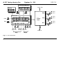
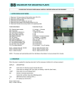
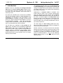
Fig.1: A-107 Overall view
2
Man Value
Clk Res CV2 CV1
Morph
Audio In
doepfer
System A - 100
2. Basic principles
Module A-107 consists of the 100% analog filter unit
with the parameters filter frequency, resonance/emphasis and amplification, and the digital control unit
with display, corresponding controls (buttons, rotary
encoder) and non-volatile memory.
The control unit manages the memory that contains
the 64 filter chains with 32 steps each. The control
unit is responsible for all parameters that refer to
switching and morphing of filters within the selected
chain, the control of the analog filter unit to obtain the
desired filter and the memory management.
The buttons "Step" and "Filter" determine if the display
shows the Step number (S) within the currenty selected filter chain (i.e. the so-called working buffer) or the
filter type (F).
The buttons "Chain" and "Prog" are used to transfer a
filter chain between the non-volatile memory (64 memories) and the working buffer.
The values for Step, Filter and Chain are set by the
endless rotary encoder labelled “Value”.
Multitype Morphing Filter
A-107
Provided that a clock signal is applied to the Step
Clock input the clocked mode is activated. In this
mode each positive transition of the clock signal triggers the advance to the next step of the filter chain in
the working buffer. If step 32 is reached the next clock
switches back to step 1 of the chain.
Addressing the filters of the chain in the working
buffer can also be controlled by the manual step
control and/or an external control voltage at one of
the Step CV inputs. According to the manual setting
and the external voltage(s) the corresponding filter
within the chain is addressed.
For both the clocked and CV addressed mode the
transition time between succeeding filters can be controlled manually by the Morphing control and/or an
external control voltage at one of the Morphing CV
inputs.
Attention: CV addressing "overruns" the filter selected
in the clocked mode.
All parameters can be controlled resp. modulated by
different voltages at the same time: filter step, morphing time, filter frequency, resonance and amplification.
3
A-107 Multitype Morphing Filter
System A - 100
doepfer
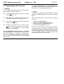
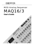
3. Overview
➆
➀
➉
➋
➇
➅
➌
➈
➍
➎
➊
4
System A - 100
doepfer
Multitype Morphing Filter
A-107
Programming Unit Controls:
Filter Unit Controls:
1 Display:
3 digit LED display
! Audio In:
audio input of the filter
2 Step:
button, calls up display mode "Step"
" Freq.:
3 Filter:
button, calls up display mode "Filter"
two CV inputs with/without attenuator,
and manual control for filter frequency
4 Chain:
button, calls up display mode "Chain"
§ Res.:
5 Prog:
button, calls up display mode "Prog"
6 Value:
rotary encoder to set the value for
Step, Filter and Chain
two CV inputs with/without attenuator,
and manual control for filter resonance/emphasis
$ Amp.:
7 Step:
two CV inputs with/without attenuator,
and manual control for Step setting
two CV inputs with/without attenuator,
and manual control for filter amplification
8 Step Clock: digital signal input for clock/gatetriggered advance to next step
% Audio Out: audio output of the filter
9 Step Reset: digital signal input to set the step to a
position within the chain defined by the
momentary step CV
0 Morph:
two CV inputs with/without attenuator,
and manual control for morphing time
5
A-107 Multitype Morphing Filter
System A - 100
4. Programming Unit Controls
1 Display
This is a 3-digit LED display with three decimal points.
These display modes are available:
doepfer
The right decimal point is a warning indicator for
the functions CHAIN and PRG and is blinking as soon
the button 4 or 5 is operated (see below).
2 Step
S01
current Step within the filter chain (= working
buffer), range 01 - 32
Operating this button calls up the display mode that
shows the current step of the chain in the working
buffer.
F01
Filter type of the currently selected step within
the chain (= working buffer), range 01 - 36
There are different was to select another step within
the chain:
C01
number of the Chain that is called up from the
memory, range 01 - 64
P01
number of the chain that is used to store
(Program) the working buffer into the memory,
range 01 - 64 (the character "S" is alread used
for Step -> P = Program)
•
•
•
•
The left and middle decimal point of the display
indicate morphing. The points are flashing alternately
while the morphing is in progress. The blinking frequency is an approximate measure for the morphing
time. As soon as the new filter type is reached both
points turn off.
6
Operate the Value control 6
Operate the manual Step control (see 7)
Altering one of the the Step CVs (see 7)
Feeding a Clock signal to socket 8.
The first two items relate to manually controlled steps.
The two last items correspond to voltage resp. clock
controlled step addressing and are suitable for automatic filter addressing and morphing (e.g. controlled
by a LFO, ADSR, random CV, Theremin, ribbon, foot
controller. MIDI-to-CV or a sequencer).
doepfer
System A - 100
3 Filter
Operating this button calls up the display mode that
shows the filter type of the currently selected step of
the chain in the display.
To select another filter type the Value control 6 has to
be operated. A detailed list of all filter types with
frequency response curves is available in chapter 7.
H
The filters are organized in two filter groups
with 18 filters each. To obtain a continuous
morphing (soft transition) for all filters within
a chain only filters from the same group have
to be used. If two succeeding filters are from
different groups a short "click" will be heard
as capacitors have to be switched between
the filter groups. Of course this characteristic
can be used intentionally for special effects.
How to program a filter chain:
D Make sure that no external control signals are fed
into the inputs Step CV 7, Step Clock 8 and Step
Reset 9. These signals would disturb the programming procedure as they change the current
step within the chain !
Multitype Morphing Filter
A-107
D Operate the Step button 2 and select the desired
step (e.g. S01) within the current filter chain
(working buffer) by using the value control 6.
D Operate the Filter button 3 and select the desired
filter type (e.g. F13) for the current step by using
the value control 6.
D Select the next step (e.g. S02) by operating the
Step button 2 and assign the filter type for this
step as described above
D Continue until all steps are programmed. It is not
necessary to program all 32 steps of a chain. If
you e.g. want only 5 different filters you may only
program the steps 1...5. But you have to pay
attention that only these programmed steps are
addressed later e.g. by the external CV (use the
attenuated CV input !)
H If you want to keep the chain in the working
buffer before you modify the settings you have
to store the working buffer into one of the 64
non-volatile memories (see item 5 PROG).
H The working buffer is erased during power off.
If you want to keep the working buffer you have
to store it into one of the 64 non-volatile memories (see item 5 PROG). After power on chain
#1 is called up from the non-volatile memory.
7
A-107 Multitype Morphing Filter
System A - 100
4 Chain
Operating this button calls up a chain from the memory, i.e. the chain is copied from the non-volatile
memory into the working buffer. To avoid wrongly
operation one has to keep the button pressed for about
one second before the function is executed.
The display shows the number of the last chain in use
(e.g. C23) and the right decimal flashes slowly as a
warning that the chain in the working buffer will be
overwritten if the process is continued.
If the chain button was operated wrongly one simply
has to operate the Step button 2 or the Filter button 3
to reach the corresponding display mode.
How to copy a chain from the memory into the working
buffer:
D
D
GET
Select the number of the desired chain by
means of the Value control 6.
Operate the Chain button again and hold it
pressed for about 2 seconds.
During this time the right decimal points flashes
fast and the display shows GET.
H If you release the chain button while the display
shows "GET" the copy procedure is interrupted
and the right decimal point flashes slowly again.
8
doepfer
After about 2 seconds the chain is copied from the
non-volatile memory into the working buffer.
5 Prog
Operating this button stores a chain into the memory,
i.e. the chain is copied from the working buffer nonvolatile memory. To avoid wrongly operation one has
to keep the button pressed for about one second
before the function is executed.
The display shows the number of the last chain in use
(e.g. P19) and the right decimal flashes slowly as a
warning that the chain in the memory will be overwritten if the process is continued.
If the chain button was operated wrongly one simply
has to operate the Step button 2 or the Filter button 3
to reach the corresponding display mode.
How to store a chain into the non-volatile memory:
D
D
Select the number of the desired chain by
means of the Value control 6.
Operate the Chain button again and hold it
pressed for about 2 seconds.
PRG During this time the right decimal points flashes
fast and the display shows GET.
doepfer
System A - 100
H If you release the button while the display shows
"PRG" the store procedure is interrupted and the
right decimal point flashes slowly again.
After about 2 seconds the chain is stored into the
selected chain of the non-volatile memory and the
display shows the latest step.
P
This operation concept makes it possible to
copy chains within the non-volatile memory.
To copy e.g. chain 17 to chain 53 one has to
copy chain 17 by means of the CHAIN function into the work buffer. Then the working
buffer is stored into chain 53 by means of the
function PROG.
6 Value
This endless rotary encoder is used to select steps,
filter types and chains as described in the sections
above.
H If an external Step CV or Step clock signal is
applied the effects of the external signals and
the value control will interfer. To select a value
with the Value control no step CV or step clock
should be applied.
Multitype Morphing Filter
A-107
7 Step
This group of controls serves to address a step within
the currently selected filter chain. It contains a manual
Step control and two Step CV inputs (one with attenuator, one without attenuator).
A variable control voltage applied to a Step CV input
leads to a step selection and consequently filter selection accordingly to the applied control voltage. The
setting of the Morphing section defines if the transition
time between succeeding steps. resp. filters.
A control voltage of 0V at Step CV input 2 corresponds
to step 01, +5V to step 32.
The effects of the manual step control and the external
step CV inputs are added up. The manual control can
be used to adjust an offset (e.g. step 16). The external
control voltage (e.g. from a LFO) could modulate the
step value around the offset (e.g. 11...21 = 16-5 ....
16+5). For bipolar control voltages (e.g. from an LFO)
an offset is required to take advantage of the full
voltage range. For positive control voltages (e.g. from
an ADSR, sequencer or MIDI-to-CV) the offset control
may be set to zero.
9
A-107 Multitype Morphing Filter
System A - 100
8 Step Clock
The positive transition (low to high) of a Clock signal
at this input advances to the next step of the current
chain.
If step 32 is reached the next clock switches back to
step 1 of the chain.
H If an external Step CV and Step clock signal is
applied the effects of both signals will interfer.
Whenever the step control voltages changes the
step corresponding to this voltage is addressed
immediately !
Therefore we recommend to apply no varying
control voltages to the Step CV inputs in the
clocked mode unless the interfering effects are
intentional.
9 Step Reset
The positive transition (low to high) at this input resets
to the step of the chain that corresponds to the
momentary step CV (manual + external). The manual
step control has to be turned to zero if a reset to step 1
is desired. A slowly varying external control voltage at
the step CV inputs can be used to reset to different
steps.
10
doepfer
The step reset input is also helpful to synchronize "filter
sequences" by applying a sequener generated reset
signal to this input (e.g. .
0 Morph
This group of controls serves to define the morphing
time between succeeding filters. It contains a manual
Morphing control and two Morphing CV inputs (one
with attenuator, one without attenuator).
Applying a slowly variable control voltage at one of
the Morphing CV leads to modulations of the morphing
time.
A control voltage of 0V at Morphing CV input 2 corresponds to a few milliseconds (~ switching), +5V to
about 10 seconds morphing time.
The effects of the manual morphing control and the
external morphing CV inputs are added up. The manual control can be used to adjust an morphing offset. The external control voltage (e.g. from a LFO or
sequencer) could modulate the morphing time the
offset. For bipolar control voltages (e.g. from an LFO)
an offset is required to take advantage of the full
voltage range. For positive control voltages (e.g. from
an ADSR, sequencer or MIDI-to-CV) the offset control
may be set to zero.
System A - 100
doepfer
5. Filter Unit Controls
! Audio In
•
Level Control
The socket is the audio input of the filter were the
audio signal has to be fed in. The attenuator controls
the input level of the signal to be filtered. If the filter’s
output signal is distorted, turn this control down, unless
the distortion is wanted as a special effect. Distortion
appears approx. above middle position of the control
(~5) for normal A-100 signals (e.g. VCO A-110).
" Frequency
This group of controls serves to define the filter frequency. It contains a manual frequency control and
two frequency CV inputs (one with attenuator, one
without attenuator).
The filter frequency is manually adjusted with the
manual frequency control. To modulate the cut-off
frequency by an external voltage (e.g. from a LFO or
ADSR) the control voltage has to be patched into one
of the two frequency control inputs. One input is
equipped with an attenuator to control the frequency
modulation amount of the corresponding input.
Multitype Morphing Filter
A-107
The effect of filter frequency depends upon the filter
type that is selected with the programming unit. In
case of a lowpass or high pass it is the cut-off frequency, for a bandpass or notch it is the middle
frequency. More details can be found in the manuals of
other A-100 filters (e.g. A-121, A-123, A-124, A-108,
A-105/122).
§ Resonance
This group of controls serves to define the filter resonance/emphasis. It contains a manual resonance
control and two resonance CV inputs (one with attenuator, one without attenuator).
The filter resonance is manually adjusted with the
manual resonance control. To modulate the resonance
by an external voltage the control voltage has to be
patched into one of the two resonance control inputs. One input is equipped with an attenuator to
control the resonance modulation amount of the corresponding input.
According to the selected filter type the resonance
effect emphasizes the frequencies around the cut-off
frequency (lowpass, highpass) or alters the bandwidth
(bandpass, notch). For the new filters without names
11
A-107 Multitype Morphing Filter
System A - 100
normally one of the frequency peaks shown in the
response curves is lifted up (see chapter 7).
For the filters 01 ... 18 (see chapter 7) the resonance
can be adjusted right up to self-oscillation, in which
case the filter will behave like a sine wave oscillator.
The filters 19...36 do not support self-oscillation.
Even the effect of resonance and self-oscillation is
treated more detailed in the manuals of other A-100
filters (e.g. A-121, A-123, A-124, A-108, A-105/122).
$ Amp.
This group of controls serves to define the filter amplitude or level. It contains a manual amplitude control
and two amplitude CV inputs (one with attenuator,
one without attenuator). This control group is assigned
to the final VCA (nothing but an exponential VCA that
is connected to the filter output).
The filter output level is manually adjusted with the
manual amplitude control. To modulate the amplitude
by an external voltage (e.g. ADSR, LFO, sequencer)
the control voltage has to be patched into one of the
two amplitude control inputs. One input is equipped
with an attenuator to control the resonance modulation
amount of the corresponding input.
12
doepfer
% Audio Out
Filter output % sends out the filtered and level controlled audio signal.
doepfer
System A - 100
Multitype Morphing Filter
A-107
6. User examples
Clocked mode
H
The advance to the next filter in the chain can be
triggered by different events. Here some examples:
In the following we use the abbreviations LP
(lowpass), BP (bandpass), HP (highpass), AP
(allpass), NF (notch filter).
P Before you continue with more complex appli-
cations of the A-107 we recommend to acquaint with the 38 filter types described in
chapter 7. Take the time to hear all the filters
and how they respond to filter frequency, resonance and distortion. Find out how morphing
between 2 filters is influenced by the morphing
time. Differences in loudness can be compensated with the amplitude control.
The easiest application is to use only one single filter
from the pool of 38 filters. This makes quite sense as
there are a lot of filters available that cannot be realized with other A-100 modules (e.g. the "fast food filter"
no. 09, look at response curve to understand the name
"fast food"). But the point of the A-107 are of course
the filter chains and the morphing features. In the
following we describe some suggestions:
• Advance triggered by a keyboard by using the gate
signal as step clock
• Advance triggered by manually operated control
devices like foot switches (A-177), Theremin
(gate output of the A-178), light controller (gate
output of the A-179), ribbon controller (gate output of the A-198)
• Random advance with the Random Clock Generator A-117 or A-149-2 (or via CV with the A-118
random CV output or one of the outputs of A-149-1)
• Periodical advance with the rectangle output of a
LFO, any clock signal or in sync with MIDI clock
(clock out of the A-190 divided by the clock divider
A-160 to obtain a smaller clock frequency)
• Rhythmical advance by means of clock divider
and sequencer A-160/161, combined e.g. with the
logic module A-166 and using the step reset input
of the A-107,
• more complex rhythmical filter sequences by
controlling the step clock by the trigger output of a
analog sequenzer (A-155 or MAQ16/3) or a trigger sequenzer (Schaltwerk)
13
A-107 Multitype Morphing Filter
System A - 100
Morphing
But the real fun arises with the morphing features of
the A-107. Even here we recommend first to find out
the sound behaviour between two different filters as it
is a big difference to morph e.g. from 6dB LP => 24 dB
LP, or LP => HP, or BP => NF, or HP => AP and so on.
For this you may use the following system:
D Program a chain with two different filter types at
step 01 and 02.
D Patch the rectangle output of a LFO to the step CV2
input of the A-107 and adjust the frequency of the
LFO to about 1 Hz or less.
D Turn the manual step control, the attenuator of step
CV2 and the manual morph control to zero.
D Select the display mode STEP.
D Look at the display and turn up the attenuator
control of step CV2 slowly until the display shows
alternately 01 and 02.
D Feed the audio input of the A-107 with the desired
audio signal. The sawtooth output of a VCO is a
good start but even a complex audio signal is
suitable for the first tests
D Set the controls of the filter section to suitable
positions: full amplitude, medium filter frequency,
small or medium resonance
D Now you will hear alternatively the two filters that
were programmed to step 01 und 02 of the chain
14
doepfer
(see first item above),
D Turn up slowly the morph control to find out how the
switching between the two filters turns more and
more into morphing.
D Alter the setting of the filter section (filter frequency,
resonance, amplitude) to hear the effect of these
controls
D Increase the LFO frequency that controls the step
CV. From a certain LFO frequency (depends upon
the setting of the morphing time) the filters of step
01 and 02 will not be reached as the morphing time
is longer than the LFO period. Instead of this one
obtains an "interim" filter that has a bit of both filters
D Use other control voltage sources (e.g. LFO,
ADSR, Random CV) to control the parameters of
the A-107 by external voltages: morphing time, filter
frequency, filter resonance, amplitude
D Extend the filter chain by adding filters to step 03,
04, 05 ... and try different filter types in the chain
Now you should experiment with a real filter chain (so
far only two filters were used) and try more sophisticated controls:
D Extend the filter chain by adding new filters to step
03, 04, 05 ... and try different filter types in the
chain. You may also use the factory setting of the
chains (step 1 = filter 2, step 2 = filter 2 ...)
doepfer
System A - 100
D Try different waveforms for the LFO that controls
the step CV and increase the effect of the step CV
by turning up the attenuator. This increases the
range of filters that were covered by the LFO CV.
D Adjust LFO frequency and attenuation, manual step
and morphing time to obtain a complete pass
through the complete chain.
D By different settings of the manual step control and
the step CV attenuator one reaches any position
within the chain (e.g. step 16) and varies the range
of filters around this position (e.g. 14...16...18
10...16...22)
D Any control voltage sources of the A-100 can be
used to control the 5 parameters of the A-107.
There are no limits to the user's imagination.
D One may control step CV, morphing time, filter
frequency, resonance and amplitude from the CV
outputs of a sequencer (e.g. A-155 or MAQ16/3),
add a little bit envelop (e.g. from the VC-Decay
A-142) to control the filter frequency, control even
the decay from a sequencer track and you will
discover "filter sequences" you never heard before.
D The voltage controlled polarizer A-133 is a suitable
tool to adjust envelopes dependent on the current
filter type. A LP with a low basic frequency requires
another envelope (normally positive) than a HP
(e.g. a negative envelope). The A-133 is very useful
to change the envelope polarity and level individually for each filter within a sequence.
Multitype Morphing Filter
A-107
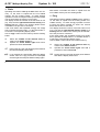
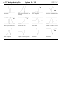
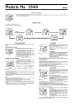
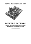
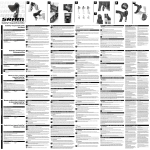
7. Filter types
The 36 filter types of the A-107 are shown on the next
pages. For each filter the frequency response curve
(X/frequency versus Y/amplitude) is shown and a short
comment is added. For some filters customary names
are available, e.g. xxdB lowpass/highpass, bandpass,
notch or allpass. For the new filters without customary
names we tried to find an explanation that describes
the filter as good as possible.
The filters are divided into two groups. The filters of
the first group (01...18) allow self-oscillation. The
filters of the second group (19...36) do not include this
feature.
15
A-107 Multitype Morphing Filter
01
02
24 dB Lowpass
12 dB Lowpass
05
Asymmetric Bandpass 2
(18 dB LP + 6 dB HP)
09
2 Bandpasses separated by a
notch ("fast food filter")
16
System A - 100
doepfer
03
Bandpass
(6 dB LP + 6 dB HP)
06
Bandpass
(12 dB LP + 12 dB HP)
Asymmetric Bandpass 1
(12 dB LP + 6 dB HP)
07
Notch + 6 dB Lowpass
10
Lowpass + shifted Bandpass
04
08
Allpass + 6 dB Lowpass
11
Lowpass + Notch I
12
"Tooth"
2 shifted Bandpasses
System A - 100
doepfer
13
Lowpass + 2 shifted Bandpasses with different amplitudes
14
2 shifted Bandpasses with different amplitudes
17
21
6 dB Highpass
Lowpass + Notch + Highpass
18 dB Lowpass
22
12 dB Highpass
16
Lowpass + Notch II
19
Lowpass with shifted Bandpass (smaller amplitude)
A-107
15
18
Lowpass + Soft Notch + Bandpass
Multitype Morphing Filter
6 dB Lowpass
23
18 dB Highpass
20
24
Asymmetric Bandpass 3
(12 dB LP + 6 dB HP)
17
A-107 Multitype Morphing Filter
System A - 100
25
doepfer
27
26
28
12 dB Notch
Allpass (lower frequencies attenuated)
29
Allpass (higher frequencies attenuated)
33
Notch + Highpass
18
Notch + Highpass
31
30
Highpass with "step"
Soft Notch + shifted Bandpass
"Wave" filter
34
Lowpass + Notch + Highpass
32
Lowpass + Soft Notch + Bandpass
35
Soft Notch I
36
Soft Notch II