1
Reference for the
Accelar 1000 Series
Command Line Interface
Software Release 2.0
Part No. 202086-B
March 1999
4401 Great America Parkway
Santa Clara, CA 95054
8 Federal Street
Billerica, MA 01821
Copyright © 1999 Bay Networks, Inc.
All rights reserved. Printed in the USA. March 1999.
The information in this document is subject to change without notice. The statements, configurations, technical data,
and recommendations in this document are believed to be accurate and reliable, but are presented without express or
implied warranty. Users must take full responsibility for their applications of any products specified in this document.
The information in this document is proprietary to Bay Networks, Inc.
The software described in this document is furnished under a license agreement and may only be used in accordance
with the terms of that license. A summary of the Software License is included in this document.
Trademarks
Bay Networks is a registered trademark of Bay Networks, Inc.
Accelar and the Bay Networks logo are trademarks of Bay Networks, Inc.
Microsoft, Windows, and Windows NT are registered trademarks of Microsoft Corporation.
All other trademarks and registered trademarks are the property of their respective owners.
Restricted Rights Legend
Use, duplication, or disclosure by the United States Government is subject to restrictions as set forth in subparagraph
(c)(1)(ii) of the Rights in Technical Data and Computer Software clause at DFARS 252.227-7013.
Notwithstanding any other license agreement that may pertain to, or accompany the delivery of, this computer
software, the rights of the United States Government regarding its use, reproduction, and disclosure are as set forth in
the Commercial Computer Software-Restricted Rights clause at FAR 52.227-19.
Statement of Conditions
In the interest of improving internal design, operational function, and/or reliability, Bay Networks, Inc. reserves the
right to make changes to the products described in this document without notice.
Bay Networks, Inc. does not assume any liability that may occur due to the use or application of the product(s) or
circuit layout(s) described herein.
Portions of the code in this software product are Copyright © 1988, Regents of the University of California. All rights
reserved. Redistribution and use in source and binary forms of such portions are permitted, provided that the above
copyright notice and this paragraph are duplicated in all such forms and that any documentation, advertising materials,
and other materials related to such distribution and use acknowledge that such portions of the software were developed
by the University of California, Berkeley. The name of the University may not be used to endorse or promote products
derived from such portions of the software without specific prior written permission.
SUCH PORTIONS OF THE SOFTWARE ARE PROVIDED “AS IS” AND WITHOUT ANY EXPRESS OR
IMPLIED WARRANTIES, INCLUDING, WITHOUT LIMITATION, THE IMPLIED WARRANTIES OF
MERCHANTABILITY AND FITNESS FOR A PARTICULAR PURPOSE.
In addition, the program and information contained herein are licensed only pursuant to a license agreement that
contains restrictions on use and disclosure (that may incorporate by reference certain limitations and notices imposed
by third parties).
#
202086-B
Bay Networks, Inc. Software License Agreement
NOTICE: Please carefully read this license agreement before copying or using the accompanying software or
installing the hardware unit with pre-enabled software (each of which is referred to as “Software” in this Agreement).
BY COPYING OR USING THE SOFTWARE, YOU ACCEPT ALL OF THE TERMS AND CONDITIONS OF
THIS LICENSE AGREEMENT. THE TERMS EXPRESSED IN THIS AGREEMENT ARE THE ONLY TERMS
UNDER WHICH BAY NETWORKS WILL PERMIT YOU TO USE THE SOFTWARE. If you do not accept these
terms and conditions, return the product, unused and in the original shipping container, within 30 days of purchase to
obtain a credit for the full purchase price.
1. License Grant. Bay Networks, Inc. (“Bay Networks”) grants the end user of the Software (“Licensee”) a personal,
nonexclusive, nontransferable license: a) to use the Software either on a single computer or, if applicable, on a single
authorized device identified by host ID, for which it was originally acquired; b) to copy the Software solely for backup
purposes in support of authorized use of the Software; and c) to use and copy the associated user manual solely in
support of authorized use of the Software by Licensee. This license applies to the Software only and does not extend
to Bay Networks Agent software or other Bay Networks software products. Bay Networks Agent software or other
Bay Networks software products are licensed for use under the terms of the applicable Bay Networks, Inc. Software
License Agreement that accompanies such software and upon payment by the end user of the applicable license fees
for such software.
2. Restrictions on use; reservation of rights. The Software and user manuals are protected under copyright laws.
Bay Networks and/or its licensors retain all title and ownership in both the Software and user manuals, including any
revisions made by Bay Networks or its licensors. The copyright notice must be reproduced and included with any
copy of any portion of the Software or user manuals. Licensee may not modify, translate, decompile, disassemble, use
for any competitive analysis, reverse engineer, distribute, or create derivative works from the Software or user manuals
or any copy, in whole or in part. Except as expressly provided in this Agreement, Licensee may not copy or transfer
the Software or user manuals, in whole or in part. The Software and user manuals embody Bay Networks’ and its
licensors’ confidential and proprietary intellectual property. Licensee shall not sublicense, assign, or otherwise
disclose to any third party the Software, or any information about the operation, design, performance, or
implementation of the Software and user manuals that is confidential to Bay Networks and its licensors; however,
Licensee may grant permission to its consultants, subcontractors, and agents to use the Software at Licensee’s facility,
provided they have agreed to use the Software only in accordance with the terms of this license.
3. Limited warranty. Bay Networks warrants each item of Software, as delivered by Bay Networks and properly
installed and operated on Bay Networks hardware or other equipment it is originally licensed for, to function
substantially as described in its accompanying user manual during its warranty period, which begins on the date
Software is first shipped to Licensee. If any item of Software fails to so function during its warranty period, as the sole
remedy Bay Networks will at its discretion provide a suitable fix, patch, or workaround for the problem that may be
included in a future Software release. Bay Networks further warrants to Licensee that the media on which the
Software is provided will be free from defects in materials and workmanship under normal use for a period of 90 days
from the date Software is first shipped to Licensee. Bay Networks will replace defective media at no charge if it is
returned to Bay Networks during the warranty period along with proof of the date of shipment. This warranty does not
apply if the media has been damaged as a result of accident, misuse, or abuse. The Licensee assumes all responsibility
for selection of the Software to achieve Licensee’s intended results and for the installation, use, and results obtained
from the Software. Bay Networks does not warrant a) that the functions contained in the software will meet the
Licensee’s requirements, b) that the Software will operate in the hardware or software combinations that the Licensee
may select, c) that the operation of the Software will be uninterrupted or error free, or d) that all defects in the
operation of the Software will be corrected. Bay Networks is not obligated to remedy any Software defect that cannot
be reproduced with the latest Software release. These warranties do not apply to the Software if it has been (i) altered,
except by Bay Networks or in accordance with its instructions; (ii) used in conjunction with another vendor’s product,
resulting in the defect; or (iii) damaged by improper environment, abuse, misuse, accident, or negligence. THE
FOREGOING WARRANTIES AND LIMITATIONS ARE EXCLUSIVE REMEDIES AND ARE IN LIEU OF ALL
OTHER WARRANTIES EXPRESS OR IMPLIED, INCLUDING WITHOUT LIMITATION ANY WARRANTY OF
MERCHANTABILITY OR FITNESS FOR A PARTICULAR PURPOSE. Licensee is responsible for the security of
its own data and information and for maintaining adequate procedures apart from the Software to reconstruct lost or
altered files, data, or programs.
202086-B
#
4. Limitation of liability. IN NO EVENT WILL BAY NETWORKS OR ITS LICENSORS BE LIABLE FOR ANY
COST OF SUBSTITUTE PROCUREMENT; SPECIAL, INDIRECT, INCIDENTAL, OR CONSEQUENTIAL
DAMAGES; OR ANY DAMAGES RESULTING FROM INACCURATE OR LOST DATA OR LOSS OF USE OR
PROFITS ARISING OUT OF OR IN CONNECTION WITH THE PERFORMANCE OF THE SOFTWARE, EVEN
IF BAY NETWORKS HAS BEEN ADVISED OF THE POSSIBILITY OF SUCH DAMAGES. IN NO EVENT
SHALL THE LIABILITY OF BAY NETWORKS RELATING TO THE SOFTWARE OR THIS AGREEMENT
EXCEED THE PRICE PAID TO BAY NETWORKS FOR THE SOFTWARE LICENSE.
5. Government Licensees. This provision applies to all Software and documentation acquired directly or indirectly by
or on behalf of the United States Government. The Software and documentation are commercial products, licensed on
the open market at market prices, and were developed entirely at private expense and without the use of any U.S.
Government funds. The license to the U.S. Government is granted only with restricted rights, and use, duplication, or
disclosure by the U.S. Government is subject to the restrictions set forth in subparagraph (c)(1) of the Commercial
Computer Software––Restricted Rights clause of FAR 52.227-19 and the limitations set out in this license for civilian
agencies, and subparagraph (c)(1)(ii) of the Rights in Technical Data and Computer Software clause of DFARS
252.227-7013, for agencies of the Department of Defense or their successors, whichever is applicable.
6. Use of Software in the European Community. This provision applies to all Software acquired for use within the
European Community. If Licensee uses the Software within a country in the European Community, the Software
Directive enacted by the Council of European Communities Directive dated 14 May, 1991, will apply to the
examination of the Software to facilitate interoperability. Licensee agrees to notify Bay Networks of any such
intended examination of the Software and may procure support and assistance from Bay Networks.
7. Term and termination. This license is effective until terminated; however, all of the restrictions with respect to
Bay Networks’ copyright in the Software and user manuals will cease being effective at the date of expiration of the
Bay Networks copyright; those restrictions relating to use and disclosure of Bay Networks’ confidential information
shall continue in effect. Licensee may terminate this license at any time. The license will automatically terminate if
Licensee fails to comply with any of the terms and conditions of the license. Upon termination for any reason,
Licensee will immediately destroy or return to Bay Networks the Software, user manuals, and all copies. Bay
Networks is not liable to Licensee for damages in any form solely by reason of the termination of this license.
8. Export and Re-export. Licensee agrees not to export, directly or indirectly, the Software or related technical data
or information without first obtaining any required export licenses or other governmental approvals. Without limiting
the foregoing, Licensee, on behalf of itself and its subsidiaries and affiliates, agrees that it will not, without first
obtaining all export licenses and approvals required by the U.S. Government: (i) export, re-export, transfer, or divert
any such Software or technical data, or any direct product thereof, to any country to which such exports or re-exports
are restricted or embargoed under United States export control laws and regulations, or to any national or resident of
such restricted or embargoed countries; or (ii) provide the Software or related technical data or information to any
military end user or for any military end use, including the design, development, or production of any chemical,
nuclear, or biological weapons.
9. General. If any provision of this Agreement is held to be invalid or unenforceable by a court of competent
jurisdiction, the remainder of the provisions of this Agreement shall remain in full force and effect. This Agreement
will be governed by the laws of the state of California.
Should you have any questions concerning this Agreement, contact Bay Networks, Inc., 4401 Great America Parkway,
P.O. Box 58185, Santa Clara, California 95054-8185.
LICENSEE ACKNOWLEDGES THAT LICENSEE HAS READ THIS AGREEMENT, UNDERSTANDS IT, AND
AGREES TO BE BOUND BY ITS TERMS AND CONDITIONS. LICENSEE FURTHER AGREES THAT THIS
AGREEMENT IS THE ENTIRE AND EXCLUSIVE AGREEMENT BETWEEN BAY NETWORKS AND
LICENSEE, WHICH SUPERSEDES ALL PRIOR ORAL AND WRITTEN AGREEMENTS AND
COMMUNICATIONS BETWEEN THE PARTIES PERTAINING TO THE SUBJECT MATTER OF THIS
AGREEMENT. NO DIFFERENT OR ADDITIONAL TERMS WILL BE ENFORCEABLE AGAINST BAY
NETWORKS UNLESS BAY NETWORKS GIVES ITS EXPRESS WRITTEN CONSENT, INCLUDING AN
EXPRESS WAIVER OF THE TERMS OF THIS AGREEMENT.
#
202086-B
Contents
Preface
Before You Begin .......................................................................................................... xxvii
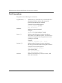
Text Conventions ......................................................................................................... xxviii
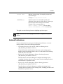
Related Publications ......................................................................................................xxix
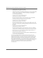
How to Get Help ........................................................................................................... xxxii
Chapter 1
Accelar Basics
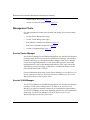
Management Tools .........................................................................................................1-2
Accelar Device Manager ..........................................................................................1-2
Accelar VLAN Manager ............................................................................................1-2
Boot Monitor Command Line Interface ....................................................................1-3
Run-Time Command Line Interface .........................................................................1-3
Accelar Configuration Page ......................................................................................1-3
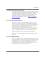
Boot Sequence ...............................................................................................................1-4
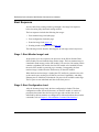
Stage 1: Boot Monitor Image Load ..........................................................................1-4
Stage 2: Boot Configuration Load ............................................................................1-4
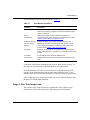
Stage 3: Run-Time Image Load ...............................................................................1-5
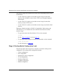
Stage 4: Routing Switch Configuration Load ...........................................................1-6
Flash/PCMCIA File System ............................................................................................1-7
Flash Memory Organization .....................................................................................1-8
Boot Flash .........................................................................................................1-8
System Flash (flash:) .........................................................................................1-8
PCMCIA (pcmcia:) .............................................................................................1-9
File Types .................................................................................................................1-9
Executables .......................................................................................................1-9
Log Files ..........................................................................................................1-10
Configuration Files ...........................................................................................1-10
Script Files .......................................................................................................1-10
Trace Logs .......................................................................................................1-10
202086-B
v
Devices and File Names ........................................................................................1-10
System Flash and PCMCIA File Names ..........................................................1-11
Reserved Devices ............................................................................................1-11
File System Commands .........................................................................................1-12
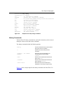
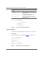
Format .............................................................................................................1-13
Directory ..........................................................................................................1-13
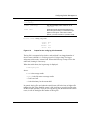
Copy ................................................................................................................1-15
Copy Script File to Running Config ..................................................................1-16
Delete ..............................................................................................................1-17
Squeeze ..........................................................................................................1-17
Recover ...........................................................................................................1-17
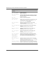
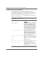
Accelar Access Levels and Passwords .........................................................................1-18
Read-Only Access .................................................................................................1-18
Layer 2 Read-Write Access ...................................................................................1-18
Layer 3 Read-Write Access ...................................................................................1-18
Read-Write Access ................................................................................................1-18
Read-Write-All Access ...........................................................................................1-19
Telnet and Console Passwords ..............................................................................1-19
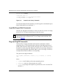
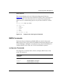
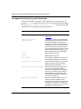
CLI Commands to Change the Console/Telnet Password ...............................1-20
Chapter 2
Boot Monitor Command Line Interface
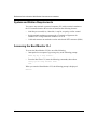
System and Station Requirements .................................................................................2-2
Accessing the Boot Monitor CLI .....................................................................................2-2
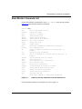
Boot Monitor Command List ...........................................................................................2-3
Boot Commands ......................................................................................................2-6
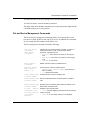
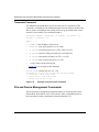
File and Device Management Commands ...............................................................2-7
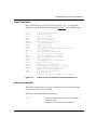
Help Commands ......................................................................................................2-9
History Commands ..................................................................................................2-9
IP Command ..........................................................................................................2-10
Ping Command ......................................................................................................2-12
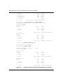
Show Command .....................................................................................................2-13
Quit Command .......................................................................................................2-14
vi
202086-B
Chapter 3
Run-Time CLI Description
System and Station Requirements .................................................................................3-1
General Usage ...............................................................................................................3- 2
Passwords ................................................................................................................3-3
Navigating through the CLI ......................................................................................3-3
Getting Help .............................................................................................................3-5
Port Numbers and IP Addresses ..............................................................................3-5
Specifying Port Numbers ...................................................................................3-5
Specifying IP Addresses and Subnet Masks .....................................................3-7
Accessing the Run-Time CLI ...................................................................................3-8
Run-Time Command List Tree ........................................................................................3-8
Navigation Commands .................................................................................................3-10
General Commands .....................................................................................................3-10
Boot Command ......................................................................................................3-11
Boot Using a Configuration Script File .............................................................3-11
Clear Commands ...................................................................................................3-12
Date Command ......................................................................................................3-12
Help Command ......................................................................................................3-13
History Commands ................................................................................................3-15
Login/Exit/Logout/Quit Commands ........................................................................3-16
Ping and PingIPX Commands ................................................................................3-16
Reset Command ....................................................................................................3-17
Traceroute Command .............................................................................................3-18
File and Device Management Commands ....................................................................3-18
Copy Script File to a Running Configuration ....................................................3-21
Accessing Files Using the Standby SSF Module .............................................3-21
Test Commands ............................................................................................................3-22
show test Commands .............................................................................................3-23
show test artable .............................................................................................3-23
show test fabric ................................................................................................3-23
show test loopback ..........................................................................................3-24
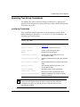
Trace Commands ..........................................................................................................3-24
show trace Commands ..........................................................................................3-25
show trace file ..................................................................................................3-25
show trace level ...............................................................................................3-25
202086-B
vii
Chapter 4
Configuring Switch Management
show config Command ...................................................................................................4-2
show tech Command ......................................................................................................4-4
CLI Management Commands .........................................................................................4-5
config cli Commands ................................................................................................4-5
show cli Commands .................................................................................................4-6
show cli info .......................................................................................................4-6
show cli who ......................................................................................................4-7
config cli password Commands ................................................................................4-7
show cli password Command ...................................................................................4-8
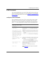
Log Commands ..............................................................................................................4-8
config log Commands ..............................................................................................4-8
show log Commands ..............................................................................................4-10
show log file .....................................................................................................4-10
show log level ..................................................................................................4-11
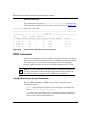
RMON Commands .......................................................................................................4-11
config rmon Commands .........................................................................................4-11
show rmon Command ............................................................................................4-12
config setdate Command ..............................................................................................4-12
System Commands ......................................................................................................4-12
Access Policy Commands ......................................................................................4-13
config sys access-policy Commands ...............................................................4-13
config sys access-policy policy Commands ....................................................4-13
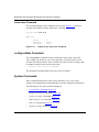
Access Policy Example ....................................................................................4-15
show sys access-policy info Command ...........................................................4-15
config sys set action Commands ...........................................................................4-16
config sys set flags Commands .............................................................................4-17
Other config sys set Commands ............................................................................4-18
show sys Commands .............................................................................................4-21
show sys community ........................................................................................4-21
show sys info ...................................................................................................4-21
show sys perf ...................................................................................................4-22
show sys sw .....................................................................................................4-23
viii
202086-B
Syslog Commands .................................................................................................4-23
config sys syslog Commands ..........................................................................4-23
show sys syslog Commands ...........................................................................4-25
Web-Server Commands ...............................................................................................4-26
config web-server Commands ...............................................................................4-26
show web-server Command ..................................................................................4-27
Chapter 5
Configuring Layer 2 Features
Port Commands ..............................................................................................................5-1
config ethernet ports Commands .............................................................................5-1
show ports Commands ............................................................................................5-4
show ports error collision ...................................................................................5-4
show ports error main ........................................................................................5-5
show ports error extended .................................................................................5-5
show ports info config ........................................................................................5-6
show ports info interface ....................................................................................5-7
show ports stats bridging ...................................................................................5-7
show ports stats interface main .........................................................................5-8
show ports stats interface extended ..................................................................5-8
show ports info vlans .........................................................................................5-9
config ethernet ports ip Commands .........................................................................5-9
Mirror Commands .........................................................................................................5-10
config mirror Commands ........................................................................................5-10
show mirrorinfo .......................................................................................................5-11
Multi-Link Trunking Commands ....................................................................................5-11
config mlt Commands ............................................................................................5-11
show mlt Commands ..............................................................................................5-12
show mlt error collision ....................................................................................5-13
show mlt error main .........................................................................................5-13
show mlt info ....................................................................................................5-14
show mlt stats ..................................................................................................5-14
202086-B
ix
Spanning Tree Group Commands ................................................................................5-15
config stg Commands ............................................................................................5-15
config ethernet ports stg Commands .....................................................................5-16
show stg Commands ..............................................................................................5-17
show stg info config .........................................................................................5-17
show stg info status .........................................................................................5-18
show ports info stg main ..................................................................................5-19
show ports info stg extended ...........................................................................5-19
show ports stats stg .........................................................................................5-20
VLAN Commands .........................................................................................................5-21
config vlan create Commands ................................................................................5-21
config vlan General Commands .............................................................................5-22
show vlan General Commands ..............................................................................5-24
show vlan info basic .........................................................................................5-24
show vlan info advance ....................................................................................5-24
show vlan info ports .........................................................................................5-25
show vlan info srcmac .....................................................................................5-25
config vlan fdb Commands .....................................................................................5-26
show vlan fdb Commands ......................................................................................5-28
show vlan info fdb-entry ...................................................................................5-28
show vlan info fdb-filter ....................................................................................5-29
show vlan info fdb-static ..................................................................................5-29
config vlan igmp-snoop Commands .......................................................................5-29
show vlan igmp-snoop Commands ........................................................................5-32
show vlan info snoop .......................................................................................5-32
show vlan igmp-snoop access-list ...................................................................5-33
show vlan igmp-snoop all-access-list ..............................................................5-34
show vlan igmp-snoop groups .........................................................................5-34
show vlan igmp-snoop senders info ................................................................5-34
show vlan igmp-snoop static ............................................................................5-35
x
202086-B
Chapter 6
Configuring Layer 3 Protocol Features
IP Routing Commands ...................................................................................................6-2
config ip Commands ................................................................................................6-2
show ip Commands ..................................................................................................6-4
show ip forwarding .............................................................................................6-4
show ip interface ................................................................................................6-4
show ip route-discovery .....................................................................................6-5
show ip route info ...............................................................................................6-5
config ip diffserv-rule Commands ............................................................................6-6
show ip diffserv rule info Command .........................................................................6-7
ethernet ports ip Commands ...................................................................................6-7
config ethernet ports ip ......................................................................................6-8
show ports info ip ...............................................................................................6-8
vlan ip Commands ...................................................................................................6-9
config vlan ip ......................................................................................................6-9
show vlan info ip ..............................................................................................6-10
IP ARP Commands ......................................................................................................6-10
config ip arp Commands ........................................................................................6-11
show ip arp Commands .........................................................................................6-12
show ip arp info ................................................................................................6-12
ethernet ip arp Commands ..............................................................................6-12
config ethernet ip arp .......................................................................................6-13
show ports info arp ..........................................................................................6-13
vlan ip arp Commands ...........................................................................................6-14
config vlan ip arp .............................................................................................6-14
show vlan info arp ............................................................................................6-15
DHCP Relay Commands ..............................................................................................6-16
config ip dhcp-relay Commands .............................................................................6-16
show ip dhcp Commands .......................................................................................6-17
show ip dhcp fwd-path .....................................................................................6-17
show ip dhcp counters .....................................................................................6-17
config ethernet ip dhcp-relay Commands ..............................................................6-17
202086-B
xi
show port dhcp Commands ...................................................................................6-18
show ports info dhcp ........................................................................................6-18
show ports stats dhcp ......................................................................................6-19
config vlan ip dhcp-relay Commands .....................................................................6-20
show vlan info dhcp .........................................................................................6-21
UDP Commands ...........................................................................................................6-21
config ip udpfwd protocol Commands ....................................................................6-22
config ip udpfwd portfwdlist Commands ................................................................6-22
config ip udpfwd interface Commands ...................................................................6-23
show ip udpfwd Commands ...................................................................................6-23
show ip udpfwd interface info ...........................................................................6-23
show ip udpfwd portfwd info ............................................................................6-24
show ip udpfwd portfwdlist info ........................................................................6-24
show ip udpfwd protocol info ...........................................................................6-24
RIP Commands ............................................................................................................6-25
config ip rip Commands .........................................................................................6-25
show ip rip Commands ...........................................................................................6-27
show ip rip info .................................................................................................6-27
show ip rip interface .........................................................................................6-27
config ethernet port ip rip Commands ....................................................................6-28
show ports info rip ...........................................................................................6-30
config vlan ip rip Commands ..................................................................................6-31
show vlan info rip .............................................................................................6-33
OSPF Commands ........................................................................................................6-34
config ip ospf Commands .......................................................................................6-34
config ip ospf ...................................................................................................6-34
config ip ospf host-route ..................................................................................6-35
config ip ospf interface .....................................................................................6-36
config ip ospf area ...........................................................................................6-37
config ip ospf area range .................................................................................6-38
config ip ospf area virtual-interface ..................................................................6-39
xii
202086-B
show ip ospf Commands ........................................................................................6-40
show ip ospf area .............................................................................................6-40
show ip ospf ase ..............................................................................................6-41
show ip ospf default-metric ..............................................................................6-42
show ip ospf host-route ....................................................................................6-42
show ip ospf ifstats ..........................................................................................6-42
show ip ospf info ..............................................................................................6-42
show ip ospf interface ......................................................................................6-43
show ip ospf int-timers .....................................................................................6-43
show ip ospf lsdb .............................................................................................6-44
show ip ospf neighbors ....................................................................................6-45
show ip ospf range ...........................................................................................6-45
show ip ospf stats ............................................................................................6-45
configure ethernet port ip ospf Commands ............................................................6-46
show port ospf Commands ....................................................................................6-48
show ports error ospf .......................................................................................6-48
show ports info ospf .........................................................................................6-48
show ports stats ospf main ..............................................................................6-49
show ports stats ospf extended .......................................................................6-49
config vlan ip ospf Commands ...............................................................................6-50
show vlan info ospf ..........................................................................................6-52
VRRP Commands ........................................................................................................6-52
config ethernet port ip vrrp Commands .................................................................6-52
show port vrrp Commands .....................................................................................6-54
show ports info vrrp main ................................................................................6-54
show ports info vrrp extended .........................................................................6-54
show ports stats vrrp .......................................................................................6-55
config vlan ip vrrp Commands ...............................................................................6-55
show vlan vrrp Commands ....................................................................................6-56
show vlan info vrrp main ..................................................................................6-56
show vlan info vrr extended .............................................................................6-56
show ip vrrp Commands ........................................................................................6-57
show ip vrrp info ...............................................................................................6-57
show ip vrrp stats .............................................................................................6-58
202086-B
xiii
IP Multicast Commands ................................................................................................6-58
config ip mroute Commands ..................................................................................6-58
show ip mroute Commands ...................................................................................6-59
show ip mroute interface ..................................................................................6-59
show ip mroute next-hop .................................................................................6-59
show ip mroute route .......................................................................................6-60
show ports stats routing Command .......................................................................6-61
DVMRP Commands ......................................................................................................6-61
config ip dvmrp Commands ...................................................................................6-61
config ip dvmrp ................................................................................................6-62
config ip dvmrp interface .................................................................................6-63
show ip dvmrp Commands ....................................................................................6-63
show ip dvmrp info ...........................................................................................6-63
show ip dvmrp interface ...................................................................................6-64
show ip dvmrp neighbor ..................................................................................6-64
show ip dvmrp next-hop ...................................................................................6-64
show ip dvmrp route ........................................................................................6-65
config ethernet ip dvmrp Commands .....................................................................6-66
show ports info dvmrp Commands ........................................................................6-66
config vlan ip dvmrp Commands ............................................................................6-67
show vlan info dvmrp .......................................................................................6-68
Layer 3 IGMP Commands ............................................................................................6-68
config ip l3 igmp Commands ..................................................................................6-68
config ip l3-igmp interface ................................................................................6-69
show ip l3 igmp Commands ...................................................................................6-70
show ip l3-igmp cache .....................................................................................6-70
show ip l3-igmp group ......................................................................................6-70
show ip l3-igmp interface .................................................................................6-71
config ethernet ip l3-igmp Commands ...................................................................6-72
show ports info l3-igmp ....................................................................................6-73
config vlan ip l3-igmp Commands ..........................................................................6-73
show vlan info l3-igmp .....................................................................................6-74
IPX Commands ............................................................................................................6-75
config ipx Commands .............................................................................................6-75
config vlan ipx Commands .....................................................................................6-78
xiv
202086-B
config ipx set Commands .......................................................................................6-78
config ipx static-route Commands ..........................................................................6-79
config ipx rip Commands .......................................................................................6-80
config ipx rip default .........................................................................................6-81
config ipx rip ....................................................................................................6-81
config ipx sap Commands ......................................................................................6-82
config ipx sap default .......................................................................................6-83
config ipx sap ...................................................................................................6-84
show ipx Commands ..............................................................................................6-84
show ipx config ................................................................................................6-85
show ipx default ...............................................................................................6-85
show ipx route ..................................................................................................6-86
show ipx sap ....................................................................................................6-86
show ipx stats ..................................................................................................6-87
show vlan info ipx ............................................................................................6-88
Chapter 7
Configuring IP Flow, Policies, and Filters
IP Flow Commands ........................................................................................................7-1
config ip flow Commands .........................................................................................7-2
show ip flow Command ............................................................................................7-2
IP Policies .......................................................................................................................7-3
config ip policy Commands ......................................................................................7-3
config ip policy info ............................................................................................7-3
config ip policy addrlist ......................................................................................7-4
config ip policy netlist .........................................................................................7-4
config ip policy ospf ...........................................................................................7-5
config ip policy ospf accept ................................................................................7-6
config ip policy ospf announce ..........................................................................7-7
config ip policy rip ..............................................................................................7-9
config ip policy rip accept ..................................................................................7-9
config ip policy rip announce ...........................................................................7-11
show ip policy Commands .....................................................................................7-13
show ip policy addrlist info ...............................................................................7-13
show ip policy netlist info .................................................................................7-14
show ip policy ospf accept info ........................................................................7-14
202086-B
xv
show ip policy ospf accept lists ........................................................................7-15
show ip policy ospf accept match network .......................................................7-15
show ip policy ospf announce info ...................................................................7-16
show ip policy ospf announce lists ...................................................................7-16
show ip policy ospf announce match network .................................................7-16
show ip policy rip accept info ...........................................................................7-17
show ip policy rip accept lists ..........................................................................7-17
show ip policy rip accept match network .........................................................7-18
show ip policy rip announce info ......................................................................7-18
show ip policy rip announce lists .....................................................................7-18
show ip policy rip announce match network ....................................................7-18
IP Filters .......................................................................................................................7-19
config ip filter Commands .......................................................................................7-19
config ip traffic-filter Commands ......................................................................7-20
config ip traffic-filter create Commands ...........................................................7-20
config ip traffic-filter filter Commands ..............................................................7-21
config ip traffic-filter filter action Command ......................................................7-22
config ip traffic-filter filter match Commands ....................................................7-23
config ip traffic-filter global-set Commands ......................................................7-24
config ip traffic-filter set Commands ................................................................7-25
config ethernet ip traffic-filter Commands ..............................................................7-26
show ip traffic-filter Commands ..............................................................................7-26
show ip traffic-filter active ................................................................................7-26
show ip traffic-filter destination ........................................................................7-27
show ip traffic-filter disabled ............................................................................7-27
show ip traffic-filter enabled .............................................................................7-27
show ip traffic-filter global ................................................................................7-28
show ip traffic-filter info global-set ...................................................................7-29
show ip traffic-filter info list ...............................................................................7-30
show ip traffic-filter interface ............................................................................7-30
show ip traffic-filter log-interval ........................................................................7-31
show ip traffic-filter source ...............................................................................7-31
show ip traffic-filter stats ..................................................................................7-31
xvi
202086-B
Chapter 8
Monitor Commands
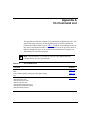
Appendix A
CLI Command List
Appendix B
Port Numbering and MAC
Address Assignment
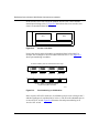
Port Numbering ............................................................................................................. B-1
MAC Address Assignment ............................................................................................. B-3
Base MAC Address ................................................................................................. B-3
Physical MAC Addresses ........................................................................................ B-4
Virtual MAC Addresses ........................................................................................... B-6
Index
202086-B
xvii
xviii
202086-B
Figures
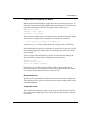
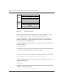
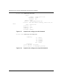
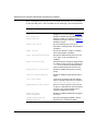
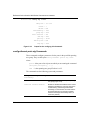
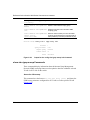
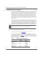
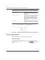
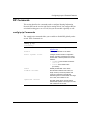
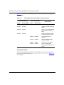
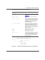
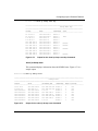
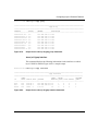
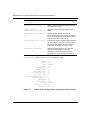
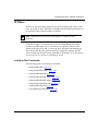
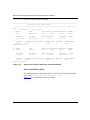
Figure 1-1.
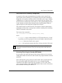
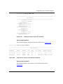
Accelar 1200 Directory Flash Example ..................................................1-14
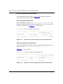
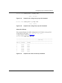
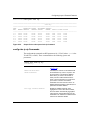
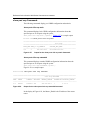
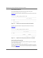
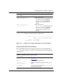
Figure 1-2.
Accelar 1100 Directory Flash Example ..................................................1-15
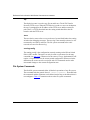
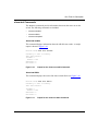
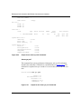
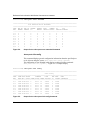
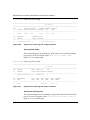
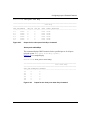
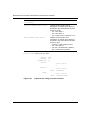
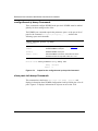
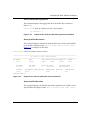
Figure 1-3.
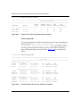
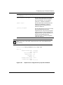
Copy Command Example ......................................................................1-16
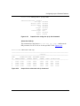
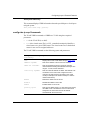
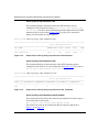
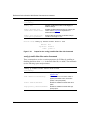
Figure 1-4.
Directory Flash Example ........................................................................1-16
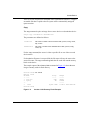
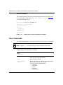
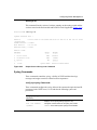
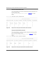
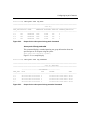
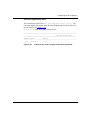
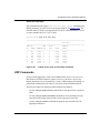
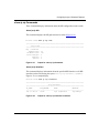
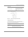
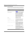
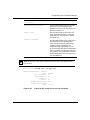
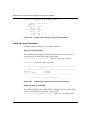
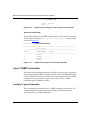
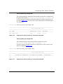
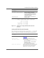
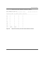
Figure 1-5.
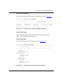
Config CLI Password Info Example ........................................................1-20
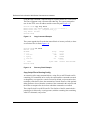
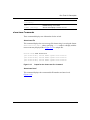
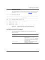
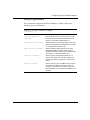
Figure 2-1.
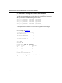
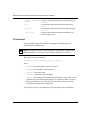
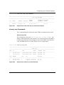
Output for the help Command in the Boot Monitor CLI ............................2-3
Figure 2-2.
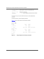
Sample Output for the directory Command .............................................2-8
Figure 2-3.
Output for the help Command in the Boot Monitor CLI ............................2-9
Figure 2-4.
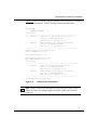
Output for the ip Command ....................................................................2-11
Figure 2-5.
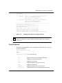
Example of Output for the ping Command .............................................2-13
Figure 2-6.
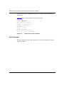
Output for the show Command ..............................................................2-14
Figure 3-1.
Accelar 1200 Slots ...................................................................................3-6
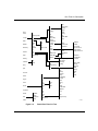
Figure 3-2.
Partial Run-Time CLI Tree .......................................................................3-9
Figure 3-3.
Output of the help Command at the Prompt ..........................................3-13
Figure 3-4.
Output for help commands in the Run-Time CLI ...................................3-14
Figure 3-5.
Output for the help config Command ....................................................3-15
Figure 3-6.
Output for the history Command ............................................................3-16
Figure 3-7.
Output from the ping Command .............................................................3-17
Figure 3-8.
Example of the traceroute Command ....................................................3-18
Figure 3-9.
Output for Some File and Device Management Commands ..................3-20
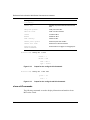
Figure 3-10. Output for the show test artable Command ...........................................3-23
Figure 3-11. Output for the show test fabric Command ..............................................3-23
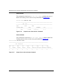
Figure 3-12. Output for the show test loopback Command ........................................3-24
Figure 3-13. Output for the show trace file Command ...............................................3-25
Figure 3-14. Output for the show trace level Command .............................................3-26
202086-B
xvii
Figure 4-1.
Partial Output for the show config Command ..........................................4-3
Figure 4-2.
Partial Output for the show tech Command .............................................4-5
Figure 4-3.
Output for the config cli info Command ....................................................4-6
Figure 4-4.
Output for the show cli info Command .....................................................4-6
Figure 4-5.
Output for the show cli who Command ....................................................4-7
Figure 4-6.
Output for the config cli password info Command ....................................4-7
Figure 4-7.
Output for the show cli password Command ...........................................4-8
Figure 4-8.
Output for the config log info Command ..................................................4-9
Figure 4-9.
Output for the show log file tail Command .............................................4-10
Figure 4-10. Output for the show log level Command ................................................4-11
Figure 4-11. Output for the show rmon Command ....................................................4-12
Figure 4-12. Output for the config sys access-policy policy Command ......................4-14
Figure 4-13. Example of Commands to Deny Access ................................................4-15
Figure 4-14. Output for the show sys access-policy info Command ..........................4-16
Figure 4-15. Output for the config sys set action info Command ...............................4-17
Figure 4-16. Output for the config sys set flags info Command .................................4-18
Figure 4-17. Output for the config sys set info Command ..........................................4-20
Figure 4-18. Output for the config sys set snmp info Command ................................4-20
Figure 4-19. Output for the show sys community Command .....................................4-21
Figure 4-20. Output for the show sys info Command .................................................4-22
Figure 4-21. Output for the show sys perf Command ................................................4-22
Figure 4-22. Output for the show sys sw Command ..................................................4-23
Figure 4-23. Output for the config sys syslog info Command .....................................4-25
Figure 4-24. Output for the show sys syslog general-info Command .........................4-25
Figure 4-25. Output for the show sys syslog host Command .....................................4-26
Figure 4-26. Output for the config web-server set info Command ..............................4-27
Figure 4-27. Output for the show web-server Command ...........................................4-27
xviii
Figure 5-1.
Output for the config ethernet info Command ..........................................5-3
Figure 5-2.
Output for the show ports error collision Command .................................5-4
Figure 5-3.
Output for the show ports error main Command ......................................5-5
Figure 5-4.
Output for the show ports error extended Command ...............................5-6
Figure 5-5.
Output for the show ports info config Command ......................................5-6
Figure 5-6.
Output for the show ports info interface Command .................................5-7
Figure 5-7.
Output for the show ports stats bridging Command .................................5-7
202086-B
Figure 5-8.
Output for the show ports stats interface main Command .......................5-8
Figure 5-9.
Output for the show ports stats interface extended Command ................5-8
Figure 5-10. Output for the show ports info vlans Command .......................................5-9
Figure 5-11. Output for the show mirrorinfo Command .............................................5-11
Figure 5-12. Output for the config mlt info Command ................................................5-12
Figure 5-13. Output for the config mlt add info Command .........................................5-12
Figure 5-14. Output for the show mlt error collision Command ..................................5-13
Figure 5-15. Output for the show mlt error main Command .......................................5-13
Figure 5-16. Output for the show mlt info Command .................................................5-14
Figure 5-17. Output for the show mlt stats Command ................................................5-14
Figure 5-18. Output for the config stg info Command ................................................5-16
Figure 5-19. Output for the config ethernet stg info Command ..................................5-17
Figure 5-20. Output for the show stg info config Command .......................................5-18
Figure 5-21. Output for the show stg info status Command .......................................5-18
Figure 5-22. Output for the show ports info stg main Command ................................5-19
Figure 5-23. Output for the show ports info stg extended Command .........................5-19
Figure 5-24. Output for the show ports stats stg Command .......................................5-20
Figure 5-25. Output for the config vlan create info Command ....................................5-22
Figure 5-26. Output for the config vlan info Command ...............................................5-23
Figure 5-27. Output for the config vlan ports info Command .....................................5-23
Figure 5-28. Output for the config vlan srcmac info Command ..................................5-23
Figure 5-29. Output for the show vlan info basic Command ......................................5-24
Figure 5-30. Output for the show vlan info advance Command .................................5-24
Figure 5-31. Output for the show vlan info ports Command .......................................5-25
Figure 5-32.
Figure 5-33.
Figure 5-34.
Figure 5-35.
Figure 5-36.
Figure 5-37.
Figure 5-38.
Figure 5-39.
Figure 5-40.
Figure 5-41.
Figure 5-42.
Figure 5-43.
202086-B
Output for the show vlan info srcmac Command ...................................5-25
Output for the config vlan fdb-entry info Command ................................. 5-27
Output for the config vlan fdb-filter info Command ................................... 5-28
Output for the config vlan fdb filter notallowfrom info Command ............. 5-28
Output for the config vlan fdb-static info Command ................................. 5-28
Output for the show vlan info fdb-entry Command ................................... 5-29
Output for the config vlan igmp-snoop info Command ............................. 5-32
Output for the show vlan info snoop Command ....................................... 5-33
Output for show vlan igmp-snoop access-list Command ......................... 5-33
Output for the show vlan igmp-snoop groups Command ......................... 5-34
Output for show vlan igmp-snoop senders info Command ...................... 5-34
Output for the show vlan igmp-snoop static Command ........................... 5-35
xix
Figure 6-1.
Output for the config ip info Command ....................................................6-3
Figure 6-2.
Output for the config ip forwarding info Command ...................................6-3
Figure 6-3.
Output for the config ip route-discovery info Command ...........................6-3
Figure 6-4.
Output for the config ip static-route info Command ..................................6-3
Figure 6-5.
Output for the show ip forwarding Command ...........................................6-4
Figure 6-6.
Output for the show ip interface Command ..............................................6-4
Figure 6-7.
Output for the show ip route-discovery Command ...................................6-5
Figure 6-8.
Output for the show ip route info Command ............................................6-5
Figure 6-9.
Output for the show ip diffserv rule info Command ..................................6-7
Figure 6-10. Output for the config ethernet ip info Command ......................................6-8
Figure 6-11. Output for the show ports info ip Command ............................................6-9
Figure 6-12. Output for the config vlan ip info Command ...........................................6-10
Figure 6-13. Output for the show vlan info ip Command ............................................6-10
Figure 6-14. Output for the config ip arp info Command ............................................6-11
Figure 6-15. Output for the show ip arp info Command .............................................6-12
Figure 6-16. Output for the config ethernet ip arp-response info Command ..............6-13
Figure 6-17. Output for the config ethernet ip proxy info Command ..........................6-13
Figure 6-18. Output for the show ports info arp Command ........................................6-14
Figure 6-19. Output for the config vlan ip proxy info Command .................................6-15
Figure 6-20. Output for the config vlan ip resp info Command ...................................6-15
Figure 6-21. Output for the show vlan info arp Command ..........................................6-15
Figure 6-22. Output for the config ethernet ip dhcp-relay info Command ..................6-18
Figure 6-23. Output for the show ports info dhcp Command .....................................6-19
Figure 6-24. Output for the show ports stats dhcp Command ....................................6-19
Figure 6-25. Output for the config vlan ip dhcp-relay info Command .........................6-20
Figure 6-26. Output for the show vlan info dhcp Command .......................................6-21
Figure 6-27. Output for the show ip udpfwd interface info Command ........................6-23
Figure 6-28. Output for the show ip udpfwd portfwd info Command ..........................6-24
Figure 6-29. Output for the show ip udpfwd protocol info Command .........................6-24
Figure 6-30. Output for the config ip rip info Command .............................................6-26
Figure 6-31. Output for show ip rip Command ...........................................................6-27
Figure 6-32. Output for show ip rip interface Command .............................................6-27
Figure 6-33. Output for the config ethernet ip rip info Command ...............................6-29
Figure 6-34. Output for the show ports info rip Command .........................................6-31
Figure 6-35. Output for the config vlan ip rip info Command ......................................6-33
xx
202086-B
Figure 6-36. Output for the show vlan info rip Command ..........................................6-33
Figure 6-37. Output for the config ip ospf info Command ...........................................6-35
Figure 6-38. Output for the config ip ospf area info Command ..................................6-38
Figure 6-39. Output for the show ip ospf area Command .........................................6-41
Figure 6-40. Output for the show ip ospf ase Command ............................................6-41
Figure 6-41. Output for the show ip ospf default-metric Command ............................6-42
Figure 6-42. Output for the show ip ospf ifstats Command ........................................6-42
Figure 6-43. Display for show ip ospf info Command ................................................6-43
Figure 6-44. Output for the show ip ospf interface Command ....................................6-43
Figure 6-45. Output for the show ip ospf int-timers Command ...................................6-44
Figure 6-46. Partial Output for the show ip ospf lsdb Command ................................6-44
Figure 6-47. Output for the show ospf neighbors Command ......................................6-45
Figure 6-48. Output for the show ip ospf stats Command ..........................................6-45
Figure 6-49. Output for the config ethernet ip ospf info Command ............................6-47
Figure 6-50. Output for the show ports error ospf Command .....................................6-48
Figure 6-51. Output for the show ports info ospf Command ......................................6-48
Figure 6-52. Output for the show ports stats ospf main Command ............................6-49
Figure 6-53. Output for the show ports stats ospf extended Command .....................6-49
Figure 6-54. Output for the config vlan ip ospf info Command ...................................6-51
Figure 6-55. Output for the show vlan info ospf Command .......................................6-52
Figure 6-56. Output for the config ethernet ports ip vrrp info Command ....................6-53
Figure 6-57. Output for the show ports info vrrp main Command ..............................6-54
Figure 6-58. Output for the show ports info vrrp extended Command .......................6-54
Figure 6-59. Output for the config vlan ip vrrp info Command ...................................6-56
Figure 6-60. Output for the show vlan info vrrp main Command ................................6-56
Figure 6-61. Output for the show vlan info vrrp extended Command .........................6-57
Figure 6-62. Output for the show ip vrrp info Command ............................................6-57
Figure 6-63. Output for the show ip vrrp stats Command ..........................................6-58
Figure 6-64. Output for the show ip mroute interface Command ...............................6-59
Figure 6-65. Output for the show ip mroute next-hop Command ...............................6-60
Figure 6-66. Output for the show ip mroute route Command .....................................6-60
Figure 6-67. Output for the show ports stats routing Command ................................6-61
Figure 6-68. Output for the config ip dvmrp info Command .......................................6-62
Figure 6-69. Output for the show ip dvmrp info Command .........................................6-63
Figure 6-70. Output for the show ip dvmrp interface Command .................................6-64
202086-B
xxi
Figure 6-71. Output for the show ip dvmrp neighbor Command ................................6-64
Figure 6-72. Output for the show ip dvmpr next-hop Command ................................6-65
Figure 6-73. Output for the show ip dvmrp route Command ......................................6-65
Figure 6-74. Output for the config ethernet ip dvmrp info Command .........................6-66
Figure 6-75. Output for the show ports info dvmrp Command ...................................6-67
Figure 6-76. Output for the config vlan <vid> ip dvmrp info Command ......................6-68
Figure 6-77. Output for the show vlan info dvmrp Command .....................................6-68
Figure 6-78. Output for the show ip l3-igmp cache Command ...................................6-70
Figure 6-79. Output for the show ip l3-igmp group Command ...................................6-71
Figure 6-80. Output for the show ip l3-igmp interface Command ...............................6-71
Figure 6-81. Output for the config ethernet ip l3-igmp info Command .......................6-72
Figure 6-82. Output for the show ports info 13-igmp Command ................................6-73
Figure 6-83. Output for the config vlan ip l3-igmp info Command ..............................6-74
Figure 6-84. Output for the show vlan info l3-igmp Command ...................................6-74
Figure 6-85. Output for the config ipx info Command .................................................6-77
Figure 6-86. Output for the config ipx forwarding info Command ...............................6-77
Figure 6-87. Output for the config ipx set info Command ...........................................6-79
Figure 6-88. Output for the config ipx static-route info Command ..............................6-80
Figure 6-89. Output for the config ipx rip info Command ............................................6-80
Figure 6-90. Output for the config ipx sap info Command ..........................................6-82
Figure 6-91. Output for the show ipx config Command ..............................................6-85
Figure 6-92. Output for the show ipx default Command .............................................6-85
Figure 6-93. Output for the show ipx route Command ...............................................6-86
Figure 6-94. Output for the show ipx sap Command ..................................................6-86
Figure 6-95. Output for the show ipx stats Command ................................................6-87
Figure 6-96. Output for the show vlan info Command ................................................6-88
xxii
Figure 7-1.
Output for the config ip flow Command ....................................................7-2
Figure 7-2.
Output for the config ip policy addrlist info Command ..............................7-4
Figure 7-3.
Output for the config ip policy netlist info Command ................................7-5
Figure 7-4.
Output for the config ip policy ospf accept info Command .......................7-7
Figure 7-5.
Output for the config ip policy ospf announce info Command ..................7-9
Figure 7-6.
Output for the config ip policy rip accept info Command ........................7-10
Figure 7-7.
Output for the config ip policy rip announce info Command ..................7-12
Figure 7-8.
Output for the show ip policy addrlist info Command .............................7-13
Figure 7-9.
Output for the show ip policy addrlist info id 1 Command ......................7-13
202086-B
Figure 7-10. Output for the show ip policy netlist info Command ...............................7-14
Figure 7-11. Output for the show ip policy netlist info id 1 Command ........................7-14
Figure 7-12. Output for the show ip policy ospf accept info Command ......................7-15
Figure 7-13. Output for the show ip policy ospf accept lists Command ......................7-15
Figure 7-14. Output for the show ip policy ospf announce info Command .................7-16
Figure 7-15. Output for the show ip policy ospf announce lists Command ...............7-16
Figure 7-16. Output for the show ip policy rip accept info Command .........................7-17
Figure 7-17. Output for the show ip policy rip accept lists Command ........................7-17
Figure 7-18. Output for show ip policy rip accept match network Command .............7-18
Figure 7-19. Output for the config ip traffic-filter info Command .................................7-20
Figure 7-20. Output for the config ip traffic-filter create info Command ......................7-21
Figure 7-21. Output for the config ip traffic-filter filter info Command .........................7-22
Figure 7-22. Output for the config ip traffic-filter filter action info Command ..............7-23
Figure 7-23. Output for the config ip traffic-filter filter match info Command ..............7-24
Figure 7-24. Output for the config ip traffic-filter global-set info Command ................7-25
Figure 7-25. Output for the config ip traffic-filter set info Command ...........................7-25
Figure 7-26. Output for the show ip traffic-filter destination Command ......................7-27
Figure 7-27. Output for the show ip traffic-filter enabled Command ...........................7-28
Figure 7-28. Partial Output for the show ip traffic-filter global Command ...................7-29
Figure 7-29. Output for the show ip traffic-filter info global-set Command .................7-29
Figure 7-30. Partial Output for the show ip traffic-filter info list Command .................7-30
Figure 7-31. Output for the show ip traffic-filter interface Command ..........................7-30
Figure 7-32. Output for the show ip traffic-filter log-interval Command ......................7-31
Figure 7-33. Output for the show ip traffic-filter source Command .............................7-31
Figure 8-1.
Output for the monitor mlt stats interface utilization Command ...............8-2
Figure 8-2.
Output for the monitor ports stats interface utilization Command ............8-3
Figure B-1.
Accelar 1200 Slots .................................................................................. B-1
Figure B-2.
Accelar 1100 Slots .................................................................................. B-2
Figure B-3.
Port Numbering on I/O Modules ............................................................. B-2
Figure B-4.
Slot and Port Numbering on the Accelar 1050/1051 Switch ................... B-3
202086-B
xxiii
xxiv
202086-B
Tables
Table 1-1.
Boot Monitor Parameters ........................................................................1-5
Table 1-2.
Accelar File System Commands ............................................................1-13
Table 1-3.
Accelar Directory Flags ..........................................................................1-14
Table 1-4.
Login and Password Default Values .......................................................1-19
Table 2-1.
Boot Monitor CLI Commands ..................................................................2-4
Table 6-1.
DiffServ Settings and TOS Values
Table 6-2.
RIP Supply and Listen Settings and Switch Action ................................6-30
Table 8-1.
Monitor and Show Commands .................................................................8-1
Table A-1.
CLI Command List ................................................................................. A-1
Table B-1.
Last Byte of Physical MAC Address ....................................................... B-5
202086-B
.........................................................6-6
xxv
xxvi
202086-B
Preface
The Bay Networks® Accelar™ command line interface (CLI) is one method used
to configure and manage an Accelar 1000 Series routing switch. The CLI, as well
as the Accelar Management Software graphical user interface (GUI), allows you
to set up, configure, and manage your Accelar routing switch as a layer 2
(switching) or as a layer 3 (routing) device.
This guide provides information about using the features and capabilities of the
CLI to perform network management operations on Accelar routing switches, as
well as a complete list of CLI commands. For general information about
networking features in Accelar products, refer to Networking Concepts for the
Accelar 1000 Series Routing Switch. For information about using the Accelar
Management Software Device Manager and VLAN Manager, refer to Reference
for Accelar Management Software Switching Operations and Reference for
Accelar Management Software Routing Operations.
Before You Begin
This guide is intended for network administrators with the following background:
202086-B
•
Basic knowledge of networks, Ethernet bridging, and IP routing
•
Familiarity with networking concepts and terminology
•
Basic knowledge of network topologies
xxix
Reference for the Accelar 1000 Series Command Line Interface
Text Conventions
This guide uses the following text conventions:
angle brackets (< >)
Indicate that you choose the text to enter based on the
description inside the brackets. Do not type the
brackets when entering the command.
Example: If the command syntax is:
you enter:
ping <ip_address>,
ping 192.32.10.12
bold text
Indicates an entered command.
Example:
Accelar 1100# show ip {alerts | routes}
braces ({})
Indicate required elements in syntax descriptions
where there is more than one option. You must choose
only one of the options. Do not type the braces when
entering the command.
Example:
config ip forwarding {true | false}
brackets ([ ])
Indicate optional elements in syntax descriptions.
Do not type the brackets when entering the command.
Example: If the command syntax is:
show ip interfaces [-alerts],
you can enter either:
show ip interfaces or
show ip interfaces -alerts.
italic text
xxx
Indicates file and directory names, new terms, book
titles, and commands.
202086-B
Preface
screen text
Indicates system output, for example, prompts and
system messages.
Example: Set Trap Monitor Filters
vertical line ( | )
Separates choices for command keywords and
arguments. Enter only one of the choices. Do not type
the vertical line when entering the command.
Example: If the command syntax is:
show ip {alerts | routes}, you enter either:
show ip alerts or show ip routes, but not both.
This guide uses the following formats to highlight special messages:
Note: This format is used to highlight information of importance or special
interest.
Related Publications
For more information about using Accelar Management Software or Accelar
routing switches, refer to the following publications:
•
Networking Concepts for the Accelar 1000 Series Routing Switch
(Bay Networks part number 205588-A)
General information and description of how the Accelar routing switch
handles various networking features, such as VLANs, Multi-Link Trunking,
OSPF, RIP, IPX, and so forth.
•
Reference for Accelar Management Software Switching Operations
(Bay Networks part number 205586-A)
Describes how to use Device Manager to configure and manage layer 2
(switching) functions with the Accelar routing switch, including procedures
and illustrations of pertinent screens.
•
Reference for Accelar Management Software Routing Operations
(Bay Networks part number 205587-A)
Describes how to use Device Manager to configure and manage layer 3
(routing) functions with the Accelar routing switch, including procedures and
illustrations of pertinent screens.
202086-B
xxxi
Reference for the Accelar 1000 Series Command Line Interface
•
Installing the Accelar 1000 Series Chassis
(Bay Networks part number 893-01051-D)
Outlines the procedures for installing and booting your Accelar routing switch
and basic switch configuration, as well as instructions for installing the
Accelar Management Software.
•
Using the Accelar 1200/1250 Routing Switch
(Bay Networks part number 893-01049-C)
Provides information about the Accelar 1200 and Accelar 1250 switches,
including operating specifications and common procedures.
•
Using the Accelar 1100/1150 Routing Switch
(Bay Networks part number 893-01050-C)
Provides information about the Accelar 1l00, Accelar 1100R, Accelar 1150,
and Accelar 1150R switches, including operating specifications and common
procedures.
•
Using the Accelar 1050/1051 Routing Switch
(Bay Networks part number 201603-C)
Provides information about the Accelar 1050 and Accelar 1051 standalone
routing switches, including operating specifications and common procedures.
•
Release Notes for the Accelar 1000 Series Products Software Release 2.0
(Bay Networks part number 896-00181-E)
Documents important information about the software or hardware that is not
covered in other related publications.
You can now print Bay Networks technical manuals and release notes free,
directly from the Internet. Go to support.baynetworks.com/library/tpubs/. Find
the Bay Networks product for which you need documentation. Then locate the
specific category and model or version for your hardware or software product.
Using Adobe Acrobat Reader, you can open the manuals and release notes, search
for the sections you need, and print them on most standard printers. You can
download Acrobat Reader free from the Adobe Systems Web site,
www.adobe.com.
xxxii
202086-B
Preface
You can purchase Bay Networks documentation sets, CDs, and selected technical
publications through the Bay Networks Collateral Catalog. The catalog is located
on the World Wide Web at support.baynetworks.com/catalog.html and is divided
into sections arranged alphabetically:
•
The “CD ROMs” section lists available CDs.
•
The “Guides/Books” section lists books on technical topics.
•
The “Technical Manuals” section lists available printed documentation sets.
Make a note of the part numbers and prices of the items that you want to order.
Use the “Marketing Collateral Catalog description” link to place an order and to
print the order form.
For more information about networking concepts, protocols, and topologies, you
may want to consult the following sources:
202086-B
•
RFC1058 (RIP version 1)
•
RFC 1723 (RIP version 2)
•
RFC 1213 (IP)
•
RFC 1389 (RIP 2 Management Information Base)
•
RFC 1493 (Bridge MIB)
•
RFC 1573 (IANAIf Type)
•
RFC 1643 (Ether-like MIB)
•
RFC 1757 (RMON)
•
RFC 1850 (OSPF MIB)
•
RFC 1583 (OSPF)
•
RFC 2178 (OSPF)
•
RFC 2338 (VRRP)
•
IEEE 802.1D (Standard for Spanning Tree Protocol)
•
IEEE 802.3 (Ethernet)
•
IEEE 802.1Q (VLAN Tagging)
•
Enterprise MIB (located on the Accelar 1000 Series Software CD)
xxxiii
Reference for the Accelar 1000 Series Command Line Interface
How to Get Help
If you purchased a service contract for your Bay Networks product from a
distributor or authorized reseller, contact the technical support staff for that
distributor or reseller for assistance.
If you purchased a Bay Networks service program, call one of the following Bay
Networks Technical Solutions Centers:
xxxiv
Technical Solutions Center
Telephone Number
Fax Number
Billerica, MA
800-2LANWAN
978-916-5314
Santa Clara, CA
800-2LANWAN
408-495-1188
Valbonne, France
33-4-92-96-69-68
33-4-92-96-69-98
Sydney, Australia
61-2-9927-8800
61-2-9927-8811
Tokyo, Japan
81-3-5402-0180
81-3-5402-0173
202086-B
Chapter 1
Accelar Basics
Bay Networks Accelar 1000 Series Routing Switches provide very high-speed
packet forwarding combined with the control of Internet Protocol (IP) routing.
Accelar switches support Gigabit Ethernet technology as well as conventional
10 megabits per second (Mb/s) and 100 Mb/s environments, combining layer 2
switching with layer 3 routing. For information about features supported in
Accelar switches, refer to Networking Concepts for the Accelar Series 1000
Routing Switch.
The Accelar 1000 Series includes the following models:
•
The Accelar 1200/1250 routing switch
•
The Accelar 1100/1150 routing switch
•
The Accelar 1050/1051 standalone routing switch
These switches can be managed in a variety of ways, mainly through the Accelar
Device Manager and VLAN Manager graphical user interfaces (GUIs) or through
the command line interface (CLI). This manual provides information about the
CLI, including lists of all available commands and parameters in Accelar software
version 2.0.
Note: For procedures to perform initial setup of the switch configured for
basic switching and routing operation, refer to Installing the Accelar 1000
Series Chassis shipped in hard copy and on the Accelar Documentation CD.
This chapter provides information about the basic operation of an Accelar 1000
Series switch. Topics covered in this chapter include the following information:
202086-B
•
Overview of management tools (page 1-2)
•
Boot sequence (page 1-4)
1-1
Reference for the Accelar 1000 Series Command Line Interface
•
Flash/PCMCIA file system (page 1-7)
•
Accelar access levels and passwords (page 1-18)
Management Tools
Five management tools enable you to monitor and manage your Accelar routing
switch:
•
Accelar Device Manager (this page)
•
Accelar VLAN Manager (this page)
•
Boot Monitor Command Line Interface (page 1-3)
•
Run-Time Command Line Interface (page 1-3)
•
Accelar Configuration Page (page 1-3)
Accelar Device Manager
Accelar Device Manager is an SNMP-based graphical user interface tool designed
to manage single devices. In order to use Accelar Device Manager, you must have
network connectivity to a management station running Accelar Device Manager
on one of the supported platforms. Accelar Device Manager is the most robust
management tool in the Accelar Management Software suite; it provides all the
functionality you need to manage a single device, including the ability to create
policy-based virtual LANs (VLANs).
For more information about using Accelar Device Manager, refer to Reference for
Accelar Management Software Switching Operations and Reference for Accelar
Management Software Routing Operations.
Accelar VLAN Manager
Accelar VLAN Manager is an SNMP-based graphical user interface tool designed
to manage VLANs across multiple devices. In order to use Accelar VLAN
Manager, you must have network connectivity to a management station running
Accelar VLAN Manager on one of the supported platforms. For more information
about using Accelar VLAN Manager, refer to the Reference for Accelar
Management Software Switching Operations.
1-2
202086-B
Accelar Basics
Boot Monitor Command Line Interface
The Boot Monitor command line interface (CLI) contains commands that enable
you to configure boot options and manage files in flash memory. Changes that can
be made and saved within the Boot Monitor CLI are boot choices, flags, IP
configuration, and Trivial File Transfer Protocol (TFTP) information. For the
Boot Monitor command list, enter help at the monitor prompt. For more
information about the Boot Monitor CLI, refer to Chapter 2, “Boot Monitor
Command Line Interface.”
Run-Time Command Line Interface
The run-time CLI performs most Accelar management tasks. To access the
run-time CLI, you need a direct connection to the switch from a terminal or PC.
Use a null-modem cable to connect the console port (DTE DB-9 male interface) to
a DTE terminal or PC. Communication parameters are as follows: 9600 bps,
8 data bits, no parity, 1 stop bit, with hardware flow control.
For pinout information about required cables, refer to Appendix A in Using the
Accelar 1200/1250 Routing Switch or Using the Accelar 1100/1150 Routing
Switch, or to Appendix B in Using the Accelar 1050/1051 Routing Switch.
You can also access the run-time CLI through a Telnet or rlogin session.
The run-time CLI commands are listed and defined in detail in the remainder of
this manual.
Accelar Configuration Page
The Accelar Configuration Page is a Web-based graphical user interface tool that
operates in conjunction with a Web browser. It has somewhat limited functionality
and is intended for use as a tool to access and monitor devices on your network
from various locations. For more information about using the Accelar
Configuration Page, refer to the section on “Web Management” in Reference for
Accelar Management Software Switching Operations.
202086-B
1-3
Reference for the Accelar 1000 Series Command Line Interface
Boot Sequence
Accelar 1000 Series routing switches go through a four-stage boot sequence
before becoming fully functional routing switches.
The boot sequence includes the following four stages:
1.
Boot monitor image load (this page)
2.
Boot configuration load (this page)
3.
Run-time image load (page 1-5)
4.
Routing switch configuration load (page 1-6)
The following sections describe what happens at each stage in the boot process.
Stage 1: Boot Monitor Image Load
At the power-up or reset sequence, the processor on the Silicon Switch Fabric
(SSF) module or board loads the boot monitor image. The boot monitor image is
contained in flash memory on the SSF module. If an Accelar 1200 routing switch
contains a redundant SSF module, the first SSF module to be installed becomes
the active SSF module on powering up or resetting. Consequently, the boot
monitor image is loaded from the flash memory on that SSF module.
When the boot monitor image is loaded, the CPU and basic system devices such
as the console port, modem port, PCMCIA card slot (if applicable), and debug
Ethernet port are initialized. Note that the I/O ports are not available at this stage.
The I/O ports are not initialized until later in the boot process.
Stage 2: Boot Configuration Load
After the bootstrap image loads, the boot configuration is loaded. The boot
configuration resides in boot flash memory on the SSF module; it consists of
parameters that control how the boot process proceeds and how the devices
initialized by the boot monitor are configured. For information about boot monitor
commands, refer to Chapter 2, “Boot Monitor Command Line Interface.”
1-4
202086-B
Accelar Basics
The boot monitor parameters are described in Table 1-1.
Table 1-1.
Boot Monitor Parameters
Parameter
Description
Autoboot
Switch automatically proceeds to stage 3. If you do not want
autoboot to proceed, the sequence can be interrupted at stage 2
via the console port.
Factory
Configuration
Determines whether the factory default configuration or a
user-defined configuration is used. For more information, refer to
“Stage 4: Routing Switch Configuration Load.”
Isolate All I/O Ports
Disables all bridging and routing and isolates all I/O ports.
Run-time Image
Sources
Specifies up to three run-time image sources and the order in
which they should be loaded. For more information about this
process, refer to “Stage 3: Run-Time Image Load.”
Config File
Allows you to specify which configuration file to use as the boot
source: flash, PCMCIA, or a script file. If not specified, the boot file
is used.
IP Address
The IP address for the diagnostic Ethernet port.
TFTP Server
A default TFTP server and file to retrieve for the bootstrap TFTP
client.
If Autoboot is disabled or interrupted at the console, the boot process stops. At
this stage, the user has access to the Boot Monitor CLI at the console.
In the Boot Monitor CLI, the user can set the boot configuration and perform
upgrades to the bootstrap image and run-time image (loaded in stage 3). Any
changes made and saved at the Boot Monitor CLI change the Boot Configuration.
After changes have been saved, the boot process can be reinitiated from the Boot
Monitor CLI with the boot command.
Stage 3: Run-Time Image Load
The run-time image loads after the boot configuration. This software image
initializes the I/O modules and provides full routing switch functionality.
202086-B
1-5
Reference for the Accelar 1000 Series Command Line Interface
The run-time image can be loaded from various sources depending on the Accelar
switch model:
•
Accelar 1200/1250 switches can load the run-time image from the flash
memory, from a PCMCIA card, or from a TFTP server using the diagnostic
Ethernet port.
•
Accelar 1100/1150 switches can load the run-time image from the flash
memory or from a TFTP server.
•
Accelar 1050/1051 switches can load the run-time image only from the flash
memory.
The factory default load order is: PCMCIA (if applicable), flash memory, and
TFTP. However, you can define the source and order from which to load the
run-time image.
•
To specify the order in the Boot Monitor CLI, use the command:
choices
See the “Boot Commands” section on page 2-6.
•
To specify the source using the run-time CLI commands, use the command:
config sys set boot
See the description on page 4-18.
Stage 4: Routing Switch Configuration Load
The final step before the boot process is complete is to load the routing switch
configuration. The routing switch configuration includes:
•
•
•
•
•
•
•
1-6
Chassis configuration
Port configuration
Spanning tree group configuration
VLAN configuration
Routing configuration
IP address assignments
RMON configuration
202086-B
Accelar Basics
The default configuration includes:
•
A single, port-based default VLAN with a VLAN identification number of 1,
bound to the default spanning tree group.
•
All ports in a single spanning tree group, STG number 1. The default
spanning tree group is 802.1D compliant, and its BPDUs are never tagged.
•
Spanning Tree FastStart disabled on all ports.
•
No interfaces assigned IP addresses.
•
Traffic priority for all ports set to normal priority.
•
All ports as nontagged ports.
Whether or not the routing switch configuration is loaded is controlled by the boot
configuration. Loading of the routing switch configuration can be bypassed in the
following ways:
•
In the Boot Monitor CLI, use the command:
flags
and answer y when prompted:
Do you want to use the factory default configuration (y/n)?
•
In the run-time CLI, issue the command:
config sys set flags factorydefault true
When the configuration is bypassed, the routing switch boots in the factory default
configuration except that the boot configuration settings were loaded in stage 2.
Bypassing the routing switch configuration does not affect the saved routing
switch configuration; the configuration is simply not loaded.
Flash/PCMCIA File System
This section describes the flash/PCMCIA file system in an Accelar switch running
version 2.X software. The flash file system in an Accelar 1000 Series routing
switch holds executable images and switch configuration. The following sections
are included:
•
•
•
•
202086-B
Flash memory organization (page 1-8)
File types (page 1-9)
Devices and file names (page 1-10)
Description of the file system commands (page 1-12)
1-7
Reference for the Accelar 1000 Series Command Line Interface
Flash Memory Organization
The Accelar routing switch has two onboard flash memory devices: Boot Flash
and System Flash. On Accelar 1200 Series switches, optional PCMCIA flash
cards can be used. These devices are described in the following sections.
Boot Flash
The Boot Flash memory is 512 kilobytes (KB) and is divided into reserved areas
for the boot monitor image and the routing switch configuration.
Boot Monitor Image
The boot monitor image is not directly user accessible. It is updated using a
special boot monitor updater that writes to the area reserved for the boot image.
Switch Configuration (config and nvram)
The routing switch configuration is written whenever a save operation is
performed on the configuration of the device. By default, the routing switch
configuration is stored in a reserved area in Boot Flash, although it is possible
to specify alternative locations in the file system for the switch configuration.
•
In the Boot Monitor CLI, use the command:
choice
•
In run-time CLI, use the command:
config sys set config <choice>.
The area reserved in Boot Flash for switch configuration is accessed by the file
system commands using the config or nvram file names. Both config and nvram
refer to the same file. Note that the switch configuration is read only when the
run-time image loads.
System Flash (flash:)
The System Flash memory is 4 megabytes (MB) and is primarily used for
run-time images, the system log, configuration files, and other general storage.
It is divided into 64K blocks. Files stored in System Flash are always stored in
an integral number of blocks.
1-8
202086-B
Accelar Basics
Files stored in System Flash are numbered sequentially starting with numeral
one (1). Files can be assigned names by the user or referenced by their ordinal
position in flash memory. The file naming convention for System Flash files is
“flash:<filename>” or “flash:<file#>.” For example, flash:3 and flash:acc2_0_0
both refer to files in System Flash. In the first case, it is the third file in System
Flash; in the latter case, it is the file named acc_2_0_0 in System Flash.
PCMCIA (pcmcia:)
Accelar 1200 Series routing switches can use an optional PCMCIA flash memory
card. PCMCIA cards can be used for general storage for all file types and are a
convenient way of moving files between switches because they are portable.
The PCMCIA card used in the Accelar 1200 and 1250 switches is the
XLR1299PC PCMCIA Flash Memory Module. It has a capacity of 4 MB of
memory with a block size of 128K. As with System Flash, files stored on
PCMCIA are numbered sequentially starting with 1 and can be given file names.
The file naming convention for PCMCIA files is “pcmcia:<filename>” or
“pcmcia:<file#>.”
File Types
Although System Flash and PCMCIA are primarily used for run-time images,
configuration files, and the system log, they are also used to store other types of
files. The following sections describe the various types of files that can be stored
in the System Flash and PCMCIA. For a given file, the file type is reflected in the
flags in a directory listing (see the “Directory” command on page 1-13).
Executables
Executables are images that are executed by the Accelar 1000 Series CPU. The
two most common executables needed by users are run-time images and boot
monitor updaters. Note that executables are stored in the flash file system in
zipped (compressed) format to conserve space. The routing switch will
automatically unzip (uncompress) the file upon execution.
Run-Time Images
The run-time image is an executable file that executes after the boot monitor
image, initializing the I/O modules and providing full routing switch functionality.
Run-time images can be stored and executed from System Flash and PCMCIA.
202086-B
1-9
Reference for the Accelar 1000 Series Command Line Interface
Boot Monitor Updaters
The boot monitor image is low-level code that initializes the devices on the Silicon
Switch Fabric Module and starts the boot process. The boot monitor image is
updated by executing a boot monitor updater that replaces the image stored in
Boot Flash.
Log Files
Console information, warning, and error messages are logged to a log file. The
log file is always stored in System Flash. On an Accelar 1200/1250 switch, if
insufficient space is found at initialization, the log is created in the PCMCIA. If no
log file is present when the run-time image executes, a new log file is created. Log
files are 128K, divided into two 64K banks. When the second bank fills, the first
bank is erased and used again.
Configuration Files
In addition to the area reserved in Boot Flash for the switch configuration,
configuration files can be stored and used in System Flash and PCMCIA.
Script Files
Script files are ASCII-based text files containing CLI commands that can be read
by the switch and the commands executed as though they were typed at a console
session.
Trace Logs
For debugging purposes, the routing switch creates a trace log with diagnostic
messages. The trace log is not normally activated, so it is not normally accessed
by end users. The file system commands refer to the reserved “trace” area for the
trace log, so this information is presented for completeness.
Devices and File Names
The Accelar 1000 Series file system supports both file naming and a simple
scheme of referencing the number of the file on the device. In addition, there are
reserved device names for reserved areas in flash memory.
1-10
202086-B
Accelar Basics
System Flash and PCMCIA File Names
Both System Flash and PCMCIA support file names. File names can be up to 31
characters long and can include printable characters and spaces. File names must
begin with a nonnumeric character. The general form of file names is:
<device>:<filename>
<device> = flash, pcmcia
<filename> = the filename
If the file name includes spaces, the entire file name should be enclosed in quotes
when used as an argument for a command. For example, the command:
copy flash:acc2_x_x “pcmcia:old image file”
copies the acc2_x_x in System Flash to the file “old image file” on PCMCIA.
Note that duplicate file names are allowed on a given device. In that case, the file
name with the highest file number (the last, nondeleted file) is the active file for
any commands.
A file on System Flash and PCMCIA can also be referenced according to the
device on which it resides and its ordinal position on that device:
<device>:<file#>
device = flash, pcmcia
file# = file number on device
For example, the first file on System Flash is flash:1 and the second file on
PCMCIA is pcmcia:2. Note that device names can be abbreviated to two letters.
For example, flash:2 and fl:2 both refer to the same file.
Reserved Devices
The file system commands take either device names or file names as arguments.
The following are reserved device names that have special meaning when used as
command arguments.
config and nvram
The config and nvram device names refer to the area of Boot Flash reserved for
the routing switch configuration. Files can be copied to and from the config and
nvram areas.
202086-B
1-11
Reference for the Accelar 1000 Series Command Line Interface
tftp
The tftp device name is used to copy files to and from a Trivial File Transfer
Protocol (TFTP) server. When the TFTP device is used as a source or destination,
the user is prompted for the IP address of the TFTP server and the remote file
path. There is a TFTP client built into the routing switch that affects the file
transfers with the TFTP server.
trace
The trace device name refers to a reserved area of system RAM where the routing
switch writes debugging messages. The trace log is not normally activated, so it is
not normally accessed by end users. The file system commands refer to the
reserved trace area for the trace log.
running config
The running config is the configuration currently running on the Silicon Switch
Fabric (SSF) module. This name can only be used as a parameter for the copy
command (see page 1-16). When used as the source of a copy, the destination will
require a script file name for the current switch configuration. When used as the
destination, the source must be a script file with CLI commands used to make
incremental changes to the current configuration state.
File System Commands
The flash file system commands allow all the basic operations of any file system.
The commands take the general form of: command <arguments>. Note that both
the commands and the arguments can be abbreviated as long as the abbreviation is
not ambiguous. Table 1-2 summarizes the Accelar file system commands.
1-12
202086-B
Accelar Basics
Table 1-2.
Accelar File System Commands
Command
Abbreviation
Description
format
fo
Formats flash or PCMCIA.
directory
di
Lists contents of flash or PCMCIA.
copy
co
Copies a file to a device appending a new file to the
destination device.
delete
de
Marks a file for deletion on a flash device.
squeeze
sq
Reclaims space used and removes files marked for
deletion.
recover
re
Unmarks a file for deletion.
Format
The format command completely and permanently erases a device, preparing the
device for use:
usage: format <device>
device = flash, pcmcia
You should run format on any new PCMCIA card to ensure that it is prepared for
use by the Accelar 1000 Series file system.
Directory
The directory command displays the contents of flash or PCMCIA:
usage: directory [<device>][-l]
device = flash, pcmcia
-l = display file details
202086-B
1-13
Reference for the Accelar 1000 Series Command Line Interface
When the directory command is invoked with no arguments, it displays the
contents of all flash devices. When a device is specified, directory displays only
the contents of that device. Information included in the directory output includes
the file number (FN), file name (Name), file size (Length) and file flags (Flags).
Flags display information about the file type and whether it is compressed or
marked for deletion. Table 1-3 lists the directory flags.
Table 1-3.
Accelar Directory Flags
Flag
Description
C
Configuration file
X
Executable file
Z
Compressed file (gzip format)
D
Marked for deletion
L
Log file
N
Directory entry in named format
T
Trace file
S
Script file - an ASCII configuration file
In Figure 1-1, files 1 and 2 are compressed executable files in version 2.x.x named
format. File 3 is a log file, file 4 is a configuration file, and file 5 is a trace file that
has been marked for deletion as indicated by the D flag.
Accelar-1200# directory flash
Device: flash
FN Name
-- ---1 acc2.x.x
2 accelar.st.100
3 syslog
4 config.100
5 system trace file
-5 files
Accelar-1200#
Figure 1-1.
Flags
----XZN
XZN
LN
CN
DT
bytes used=
Length
-----939357
895483
130896
4200
65360
-----2162688 free=2031616
Accelar 1200 Directory Flash Example
The -l option in directory shows the file details. In particular, it shows the original
file name of any run-time executables.
1-14
202086-B
Accelar Basics
There are no file compression commands in the command line interface. A zipped
executable file that is copied to the file system will be automatically unzipped
upon execution.
Copy
The copy command copies an image from a source device to a destination device:
usage: copy <srcdevfile> <destdevfile>
The parameters are defined as follows:
srcdevfile
File name or number of the source file in flash, pcmcia, config, nvram,
tftp, or trace
destdevfile
File name or number of the destination file in flash, pcmcia, config,
nvram, tftp
For the copy command, the source is either a specific file or one of the reserved
device names.
If a destination file name is not specified, the file name will stay the same as the
source file name. The copy command appends the file to the last unused memory
block on the device.
The sample output of the directory flash command in Figure 1-2 shows that two
images currently reside in flash memory.
Accelar-1100# dir flash
Device: flash
FN Name
-- ---1 acc2.x.x
2 syslog
-2
files
Flags
----XZN
LN
bytes used=
Length
-----939357
130896
-----1114112 free=3080192
Accelar-1100#
Figure 1-2.
202086-B
Accelar 1100 Directory Flash Example
1-15
Reference for the Accelar 1000 Series Command Line Interface
Using the copy command, a run-time image is copied to flash from a TFTP server.
The source argument is not a file name but rather tftp. The system prompts the
user for the TFTP server IP address and the remote file path (Figure 1-3).
Accelar-1100# copy tftp flash
Enter source tftp server address [0.0.0.0]: 10.10.20.1
Enter source file [/]: /tftpboot/acc2_x_0
tftp result: success
Accelar-1100#
Figure 1-3.
Copy Command Example
The system appends the file to the last unused block of memory on flash, so there
are now three files in flash (Figure 1-4).
Accelar-1100# dir flash
Device: flash
FN Name
-- ---1 acc2.x.x
2 syslog
3 acc2.x.0
-3
files
Flags
----XZN
LN
XZ
Length
-----939357
130896
895483
-----bytes used= 2031616 free=2162688
Accelar-1100#
Figure 1-4.
Directory Flash Example
Copy Script File to Running Config
An extension of the copy command allows a script file (an ASCII-based text file
containing CLI commands) to be read by the switch and the commands executed
as though they were typed at a console session. By default, script execution does
not display at the device where the command was issued. However, if the optional
debug parameter is used, then the execution of the command in the script file and
the results are output to the device from which the command was executed.
The script file itself is an ASCII text file. The first line of the file must include a
pound sign (#) followed by a carriage return, with the remaining lines containing
valid CLI commands, one per line.
1-16
202086-B
Accelar Basics
The format of the command is:
copy <sourcedevice:filename> running-config [debug]
where:
may be a flash, PCMCIA, or TFTP-based file server. If “tftp”
is specified, you will be prompted for the server IP address and the file name.
sourcedevice
filename
[debug]
is the name of the file to be copied.
is the optional parameter that allows viewing execution of the script.
Note: Use care when executing script files from within the CLI. The command
execution will reference from your current position in the directory structure.
Delete
The delete command marks a file for deletion on a device:
usage: delete <devfile>
devfile = filename or file number of the flash or pcmcia file;
device name or number can be included
Note that the delete command only marks a file for deletion but does not actually
erase the file. To free the space used by a deleted file, use the squeeze command.
Squeeze
The squeeze command reclaims deleted file space on a device:
usage: squeeze <device>
device = flash, pcmcia; device name or number can be included
Note that the files will be renumbered after a squeeze.
Recover
The recover command is used to unmark all files on the device already marked for
deletion:
usage: recover <device>
device = flash, pcmcia
202086-B
1-17
Reference for the Accelar 1000 Series Command Line Interface
Accelar Access Levels and Passwords
The Accelar 1000 Series devices employ a security scheme with five levels of
management access. The five levels of security access are:
•
•
•
•
•
Read-Only
Layer 2 Read-Write
Layer 3 Read-Write
Read-Write
Read-Write-All
Read-Only Access
Read-Only access allows the manager to view the device settings, but changes are
not allowed.
Layer 2 Read-Write Access
Layer 2 (L2) Read-Write access allows the manager to view and edit device
settings dealing with layer 2 (bridging) functionality. The layer 3 settings (such as
OSPF, DHCP) are not accessible. The only layer 2 device settings that cannot be
changed with Read-Write access are the security and password settings.
Layer 3 Read-Write Access
Layer 3 (L3) Read-Write access allows the manager to view and edit device
settings dealing with layer 2 (bridging) and layer 3 (routing) functionality.
The only layer 2 or layer 3 device settings that cannot be changed with
Read-Write access are the security and password settings.
Read-Write Access
Read-Write access allows the manager to view and edit most device settings.
The only device settings that cannot be changed with Read-Write access are the
security and password settings.
1-18
202086-B
Accelar Basics
Read-Write-All Access
Read-Write-All access allows all the privileges of Read-Write access and the
ability to change the security settings. The security settings include access
passwords and the Web-based management user names and passwords.
Telnet and Console Passwords
When an Accelar 1000 Series routing switch is accessed for management, the user
is prompted for a login name and a password. The default values for login and
password console and Telnet sessions are shown in Table 1-4.
Table 1-4.
Login and Password Default Values
Access Level
Default Login
Default Password
Read-Only
ro
ro
Layer 2 Read-Write
l2
l2
Layer 3 (and Layer 2) Read-Write
l3
l3
Read-Write
rw
rw
Read-Write-All
rwa
rwa
Logins and passwords can be changed only if you log in with Read-Write-All
privileges (that is, the rwa access level). The login name for different modes can
also be changed. When the CLI prompts for login and password, the access level
is set corresponding to the login and password pair entered.
The login command allows you to log in again with a different login access by
entering the user name and password. The prompt remains at the same level that
you were before logging in again.
The logout command allows the user to log out and reenter at the top level prompt.
If you connect to the routing switch through Telnet, logout terminates the Telnet
session.
202086-B
1-19
Reference for the Accelar 1000 Series Command Line Interface
CLI Commands to Change the Console/Telnet Password
The following commands can be used to change the console/Telnet login name
and the password for each different login access level:
config
config
config
config
config
cli
cli
cli
cli
cli
password
password
password
password
password
ro <username> [<password>]
rw <username> [<password>]
l2 <username> [<password>]
l3 <username> [<password>]
rwa <username> [<password>]
To display information about the access levels for login and password, type:
show cli password
See the example in Figure 1-5.
********************************
* Bay Networks,Inc.
*
* Copyright (c) 1996-1999
*
* All Rights Reserved
*
* Accelar 1100
*
* Software Release 2.0
*
********************************
Login: rwa
Password: ***
Accelar-1100# show cli password
Access
Login
Password
rwa
rwa
rwa
rw
rw
rw
l3
l3
l3
l2
l2
l3
ro
ro
ro
Accelar-1100/cli/password#
Figure 1-5.
1-20
Config CLI Password Info Example
202086-B
Chapter 2
Boot Monitor Command Line Interface
The Boot Monitor CLI commands enable you to configure boot options and
manage files on the flash module; they are used when the switch is not active.
The Boot Monitor commands enable you to perform the following tasks:
•
Configure and display boot options, including the configuration file
•
Manage the NVRAM (flash) file system
•
Configure and change IP parameters for system devices
•
Change boot flags
•
Reset or reboot the system with the default configuration
•
Reset or reboot the system from a different boot source
This chapter describes the Boot Monitor CLI and covers the following topics:
202086-B
•
System and Station Requirements (page 2-2)
•
Accessing the Boot Monitor CLI (page 2-2)
•
Boot Monitor Command List (page 2-3)
2-1
Reference for the Accelar 1000 Series Command Line Interface
System and Station Requirements
You can use any terminal or personal computer (PC) with a terminal emulator as
the CLI command station. Be sure the terminal has the following features:
•
9600 bits per second (b/s), 8 data bits, 1 stop bit, no parity, no flow control
•
Serial terminal-emulation program such as Terminal or Hyperterm for
Windows NT ® or Hyperterm for Windows® 95 or 98
•
Cable and connector to match the Accelar switch male DTE connector (DB-9)
Accessing the Boot Monitor CLI
To access the Boot Monitor CLI, do one of the following:
•
Interrupt the boot sequence by pressing a key at the following prompt:
Press any key to stop autoboot.
•
From the Run-Time CLI, enter the following commands, then reboot:
config sys set flags autoboot false
save
When you enter the Boot Monitor CLI, the following prompt is displayed:
monitor>
2-2
202086-B
Boot Monitor Command Line Interface
Boot Monitor Command List
For the Boot Monitor command list, enter help
Figure 2-1 shows the Boot Monitor commands.
commands
at the monitor prompt.
monitor> help
boot
boot an image from a device
choices
copy
date
delete
devices
directory
flags
format
help
history
ip
recover
reset
save
setdate
change boot order
copy file to device
read realtime clock
delete file from device
enable/disable boot devices
list files on device
change boot flags
format device
enter help <command> for additional information.
list command history
change ip address information for the diag port, if
present.
system log file information
ping an ip address on a network from the diag port, if
present.
recover deleted files on a device
reset the system
save changes to boot configuration
write realtime clock
show
squeeze
tests
tftp
trace
quit
?
display boot configuration
reclaim deleted file space on a device
enable/disable device boot-up tests
change tftp server information
system trace file information
quit menu and boot
enter help <command> for additional information.
log
ping
Figure 2-1.
Output for the help Command in the Boot Monitor CLI
For information about the boot load process, refer to page 1-4.
202086-B
2-3
Reference for the Accelar 1000 Series Command Line Interface
Table 2-1 lists the commands in the Boot Monitor CLI and the reference page
numbers where you can find more information.
Table 2-1.
Boot Monitor CLI Commands
Commands
See page
Boot commands—Use these commands to display and modify boot
parameters and to reboot the Accelar 1000 Series Chassis.
boot [device> [:filename] <cfgfile> [<tftp> <file>]]
choices [<choice> <source>[:<filename>]]
devices [<device name or device number>]
flags
reset
save
tests [<device name or device number>]
tftp [<server ip address> <file>]
Note: Entering a boot command with no arguments will cause the
switch to follow the current boot choices and boot the switch.
File and device management commands—Use these commands to
manage system software files and configuration files and to manage the
flash module and PCMCIA card.
copy [<src device>[:filename] <dest device> [:filename>] ]
delete <device name or device number> <:filename>
directory <device name or device number>
format <device name or device number>
recover <device name or device number>
squeeze <device name or device number>
help command—Use this command to list all Boot Monitor commands or to
display syntax for a command.
help <command>
History commands—Use these commands to display and reenter
previously entered commands. Syntax is the same as the Run-Time CLI
history command.
!!
!<number>
!<str>
!?<substr>
^<sstr>^<rstr>
ip command—Use this command to assign an IP address to the diagnostic
Ethernet port.
ip [<device> <ipaddr> <netmask> <gateway> <mgmtnet>]
2-4
202086-B
Boot Monitor Command Line Interface
Table 2-1.
Boot Monitor CLI Commands (continued)
Commands
See page
ping command—Use this command to test the network connection
between the Accelar 1000 Series Chassis diagnostic port and another
networking device.
ping <device> <ipaddr> [<size>]
quit command—Use this command to end the Boot Monitor CLI session
and reboot the Accelar 1000 Series Chassis.
quit
show command—Use this command to display boot configuration
parameters.
show [<configuration type>]
log command—Use this command to display system log information.
log create<device>
log clear <device>: <filename> <nblocks>
log show <device> <filename> [tail]
trace command—Use this command to display trace file information.
trace show [tail] <device> [:filename> ]
202086-B
2-5
Reference for the Accelar 1000 Series Command Line Interface
Boot Commands
The boot commands enable you to display and modify boot parameters and to
reset or reboot the system.
Note: Entering a boot command with no arguments will cause the switch to
follow the current boot choices and boot the switch.
The boot commands include the following:
2-6
boot[<device>
[:filename]
<cfgfile>
[<tftp> <file>]]
Boots the switch.
• device is the name or number of a boot device.
• filename is the software image file name.
• cfgfile is the software configuration device and file or
NVRAM file name.
• <tftp> <file> specifies a file that is on the TFTP server.
choices
[<choice> <source>
[:<filename>]]
Displays or changes the order in which the boot sources (flash
and PCMCIA card) are accessed.
• choice is the order in which the specified boot device is
accessed when you reboot the switch: primary, secondary,
or tertiary.
• source is the boot source (none, flash, pcmcia, net, skip).
If you specify none, no boot source will be accessed for the
choice (primary, secondary, or tertiary) you are configuring.
If you specify skip, the choice you are configuring will be
skipped.
devices <device name
or device number>
Enables or disables the specified boot device.
flags
Enables or disables autoboot and booting using the default
configuration settings.
reset
Resets the system by loading the configuration file or by using
the default settings.
save
Saves changes to the boot configuration parameters.
show
Displays the boot configuration parameters.
tests <device name
or device number>
Enables or disables the bootup diagnostic tests.
tftp
Changes TFTP server information.
help
Lists all Boot Monitor commands or displays syntax for a
command.
202086-B
Boot Monitor Command Line Interface
To list the boot devices on your routing switch, enter the show devices command.
To list the file names, enter the directory command.
The flags, reset, save, and tftp commands do not require parameters; flags and tftp
commands prompt you to select options.
File and Device Management Commands
The file and device management commands enable you to manage files on the
boot devices (flash, PCMCIA card, and TFTP server). In addition, the commands
let you manage the flash module and PCMCIA card.
The file management commands include the following:
202086-B
copy <src device>
[:filename]
<dest device>
[:filename]
Copies a file from one boot device to another or copies it to
the same boot device under a new file name. With no
arguments, it prompts the user.
• src device is the device from which you are copying
a file.
• dest device is the device onto which you are copying
a file.
• filename is a file name.
delete <device>
[:filename>
Deletes a file from a flash or PCMCIA device.
directory <device
name or device
number> [-l]
Lists the files on a flash or PCMCIA device.
• <device name or device number> is the file device:
flash or PCMCIA.
• [-l] represents file details.
format <device name
or device number>
Formats the flash module or PCMCIA card.
recover <device name
or device number>
Recovers a file deleted from the flash module or PCMCIA
card.
squeeze <device name
or device number>
Reclaims space occupied by files marked for deletion on the
flash module or PCMCIA card.
log show
<device>
<:filename> [tail ]
Displays system log information.
• [tail] requests displaying information from the back first.
log create <device>
[:<filename>]
<nblocks>
Creates a log file.
• [nblocks] is the number of blocks to be displayed.
2-7
Reference for the Accelar 1000 Series Command Line Interface
log clear <device>
[:filename>
Clears log files on a device or the specified log file.
trace show [tail]
[device>
[:filename>]
Displays trace information.
• [tail] requests displaying information from the back first.
To list devices on your Accelar 1000 Series chassis, use the show devices
command.
To list the file names, enter the directory command.
Figure 2-2 shows sample output for the directory command.
monitor> dir
Device: flash
FN Name
-- ---1 acc2.x.x
-1
files
Device: pcmcia
FN Name
-- ---1 acc2.x.x
-1
files
Flags
----XZN
bytes used=
Flags
----XZN
bytes used=
Length
-----961227
-----983040 free=3211264
Length
-----961227
-----1048576 free=3145728
monitor>
Figure 2-2.
2-8
Sample Output for the directory Command
202086-B
Boot Monitor Command Line Interface
Help Commands
Help is available at every level of the CLI by typing ? or help. Typing help
displays a list of the Boot Monitor commands. Figure 2-3 shows sample output.
boot
choices
copy
date
delete
devices
directory
flags
format
help
history
ip
log
ping
recover
reset
save
setdate
show
squeeze
tests
tftp
trace
quit
?
boot an image from a device
change boot order
copy file to device
read realtime clock
delete file from device
enable/disable boot devices
list files on device
change boot flags
format device
enter help <command> for additional information
list command history
change ip address information
list system log file information
ping an ip address on a network
recover deleted files on a device
reset the system
save changes to boot configuration
write realtime clock
display boot configuration
reclaim deleted file space on a device
enable/disable device bootup tests
change tftp server information
list trace file configuration
quit menu and boot
enter help <command> for additional information
Figure 2-3.
Output for the help Command in the Boot Monitor CLI
History Commands
The history commands let you list the commands you have entered during the
current session and reenter commands.
The history commands include the following:
202086-B
history
Lists the commands that you have entered during the
current CLI session.
!!
Reenters the most recently entered command.
2-9
Reference for the Accelar 1000 Series Command Line Interface
!<number>: run command
<number>
Enters the command identified in the command history by
!<str>
Runs the last command that matches the given string
<number>.
<str>.
!?<substr>
Runs the last command that matches the given substring
<substr>.
^<sstr>^<rstr>
Enters the most recent command but substitutes a new
string for a given string.
IP Command
The ip command assigns an IP address to the diagnostic Ethernet port for
troubleshooting and diagnostics.
Note: For normal operation, you should not have an IP address assigned to the
diagnostic Ethernet or serial port. The IP address should be set to 0.0.0.0.
The syntax for the ip command is:
ip [<device> <ipaddr> <netmask> <gateway> <mgmtnet>]
where:
•
<device>
is the network device name or number.
•
<ipaddr>
is the IP address in dot notation .
•
<netmask>
is the subnet mask.
•
<gateway>
is the default router IP address.
•
<mgmtnet> is the management station network IP
address. You need to use this
argument only if the management station is on a different subnet. If you use
this argument, the Accelar 1000 Series Chassis enters a static route to the
management network in the routing table.
If you do not use any of the arguments, the CLI prompts you for information.
2-10
202086-B
Boot Monitor Command Line Interface
Figure 2-4 shows an example of the ip command. In this example, the command is
issued without arguments, so the CLI prompts for the argument values.
monitor> ip
--CHANGE IP ADDRESS
--Net Devices:
---------------------------------------------------------------4
Enabled
Serial Port 2 [s2] hw=ff:ff:ff:ff:ff:ff
ip=0.0.0.0 netmask=0x00000000
mgmt net=0.0.0.0 gateway=0.0.0.0
5
Enabled
Debug Ethernet [nic] hw=00:e0:16:04:66:00
ip=0.0.0.0 netmask=0x00000000
mgmt net=0.0.0.0 gateway=0.0.0.0
---------------------------------------------------------------select network interface device [5]:
Enter ip address [0.0.0.0]:
Enter netmask [255.0.0.0]:
Enter default gateway [0.0.0.0]:
Enter Mgmt Network [0.0.0.0]:
Net Devices:
---------------------------------------------------------------4
Enabled
Serial Port 2 [s2] hw=ff:ff:ff:ff:ff:ff
ip=0.0.0.0 netmask=0x00000000
mgmt net=0.0.0.0 gateway=0.0.0.0
5
Enabled
Debug Ethernet [nic] hw=00:e0:16:04:66:00
ip=0.0.0.0 netmask=0xff000000
mgmt net=0.0.0.0 gateway=0.0.0.0
---------------------------------------------------------------ip configuration has been saved
Figure 2-4.
Output for the ip Command
Note: The Net 4 Serial port entry applies to the modem port on the Accelar
1200/1250 switch. You cannot assign an IP address to this port in software
release 2.0.
202086-B
2-11
Reference for the Accelar 1000 Series Command Line Interface
Ping Command
The Boot Monitor ping command allows you to test the connection between the
Accelar 1000 Series chassis and another networking device. The syntax for the
Boot Monitor ping command is:
ping <ipaddr> [<datasize> <count>]
where:
is the IP address of the other networking device.
•
<ipaddr>
•
<datasize> <count>
•
<size>
is any integer value equal to or greater than 1. The default is 1.
Figure 2-5 illustrates an example of output.
monitor> ping
--PING TEST
--Net Devices:
---------------------------------------------------------------4
Enabled
Serial Port 2 [s2] hw=ff:ff:ff:ff:ff:ff
ip=0.0.0.0 netmask=0x00000000
mgmt net=0.0.0.0 gateway=0.0.0.0
5
Enabled
Debug Ethernet [nic] hw=00:e0:16:04:66:00
ip=0.0.0.0 netmask=0xff000000
mgmt net=0.0.0.0 gateway=0.0.0.0
---------------------------------------------------------------select network interface device [5]:
Enter destination ip address [192.168.1.1]:
Enter ping size [48]:
Using [nic] to ping. press any key to stop.
ENET: hold frame collision, outbound frame.
2 packets transmitted, 0 packets received, 100% packet loss
monitor> ping
--PING TEST
---
2-12
202086-B
Boot Monitor Command Line Interface
Net Devices:
---------------------------------------------------------------4
Enabled
Serial Port 2 [s2] hw=ff:ff:ff:ff:ff:ff
ip=0.0.0.0 netmask=0x00000000
mgmt net=0.0.0.0 gateway=0.0.0.0
5
Enabled
Debug Ethernet [nic] hw=00:e0:16:04:66:00
ip=0.0.0.0 netmask=0xff000000
mgmt net=0.0.0.0 gateway=0.0.0.0
---------------------------------------------------------------select network interface device [5]:
Enter destination ip address [192.168.1.1]:
Enter ping size [48]:
Using [nic] to ping. press any key to stop.
ENET: hold frame collision, outbound frame.
ENET: hold frame collision, outbound frame.
2 packets transmitted, 0 packets received, 100% packet loss
Figure 2-5.
Example of Output for the ping Command
Note: The Net 4 Serial port entry applies to the modem port on the Accelar
1200/1250 switch. You cannot assign an IP address to this port in software
release 2.0.
Show Command
The show command displays chassis configuration information. The syntax for
the show command is:
show [<configuration type>]
where:
configuration type
202086-B
is one of the following:
info
Displays general chassis configuration information.
ip
Displays IP configuration information.
boot
Displays the boot choices.
tftp
Displays information about the TFTP server.
tests
Displays test information.
devices
Displays information about the boot devices.
environment
Displays information about the SSF module and chassis.
2-13
Reference for the Accelar 1000 Series Command Line Interface
If you do not specify a configuration type, the CLI displays all the configuration
information.
Figure 2-6 shows sample output for the show command.
monitor> show boot
User Selected Boot Sources
--------------------------Primary
= pcmcia:acc2.0.0.b9
Secondary = flash:acc2.0.0
Tertiary = net
Config
= nvram
Autoboot is enabled
Factory defaults is disabled
Switch port isolation is disabled
Figure 2-6.
Output for the show Command
Quit Command
The quit command ends your Boot Monitor CLI session and reboots the Accelar
1000 Series chassis.
2-14
202086-B
Chapter 3
Run-Time CLI Description
In Accelar 1000 Series routing switches, the run-time CLI commands enable
you to display and modify the routing switch configuration while the switch is
operating. This chapter includes information about the run-time CLI in the
Accelar software. It includes the following sections:
•
System and Station Requirements (this page)
•
General Usage (page 3-2)
•
Run-Time Command List Tree (page 3-8)
•
Navigation Commands (page 3-10)
•
General Commands (page 3-10)
•
File and Device Management Commands (page 3-18)
•
Test Commands (page 3-22)
•
Trace Commands (page 3-24)
System and Station Requirements
You can use any terminal or personal computer (PC) with a terminal emulator as
the CLI command station. Be sure the terminal has the following features:
202086-B
•
9600 bits per second (b/s), 8 data bits, 1 stop bit, no parity, no flow control
•
Serial terminal-emulation program such as Terminal for Windows NT or
Hyperterm for Windows 95 or 98.
•
Cable and connector to match the Accelar switch male DTE connector (DB-9)
3-1
Reference for the Accelar 1000 Series Command Line Interface
You can access the CLI through a direct serial-port connection to the switch, or for
run-time CLI, you can also access through a Telnet connection or asynchronous
dial-up modem. Accelar switches support up to two CLIs at the modem and
console serial ports and up to eight Telnet sessions.
Note: Some features require ARU2 or ARU3 hardware to function. To
determine the hardware version(s) in your chassis, use the command
show system info. The resulting display will indicate the ARU level of
the chassis and, if applicable, the cards.
General Usage
When the switch is up and running, the Run-Time CLI commands enable you
to perform most of the configuration and management functions necessary to
manage the Accelar switch. These functions include the following:
3-2
•
Reset or reboot the Accelar 1000 Series chassis.
•
Save your configuration to NVRAM (nonvolatile RAM).
•
Add, delete, and display ARP table entries.
•
Configure RIP, DHCP, OSPF, VRRP, IGMP, DVMRP, and IPX parameters.
•
Ping another networking device.
•
Display and set configuration parameters for the entire Accelar 1000 Series
chassis and for individual ports.
•
Add and delete static IP routes (including default routes) in the IP route table.
•
Configure and display spanning tree group (STG) parameters and enable or
disable Spanning Tree Protocol on an STG.
•
Configure and display Multi-Link Trunking (MLT) parameters.
•
Set IP policies for RIP and OSPF.
•
Set traffic filters for the switch.
•
Test the Accelar 1000 Series chassis switching fabric and perform internal and
external loopback tests on individual ports.
•
Create and manage port-based VLANs or policy-based VLANs.
202086-B
Run-Time CLI Description
Note: The CLI commands enable you to perform most configuration tasks, but
not all tasks can be performed using the CLI (in particular, setting RMON
parameters). To perform a task that cannot be performed using CLI commands,
use the Accelar Device Manager.
Passwords
There are five defined levels of password-protected access to the CLI:
•
ro (Read-Only)
•
L2 (layer 2 Read-Write)
•
L3 (layer 2 and layer 3 Read-Write)
•
rw (Read-Write for all levels)
•
rwa (Read-Write-All)
When you access the CLI, it prompts for login and password and sets your access
level accordingly. Only users with rwa access can change login names and
passwords.
Navigating through the CLI
The CLI is organized into a tree data structure. Help can be accessed from any
level of the tree by typing a question mark (?). Typing the word help provides an
explanation of the available help. Typing help <command> will explain what the
command does and give the syntax. Typing ? results in a list of all commands.
Typing "syntax" displays a path list of commands and parameters available from
the current prompt or <command> forward. It lists the syntax in the current context.
When you type a command, you may see context and subcontext. Context
indicates commands at that level. Subcontext indicates one or more command
layers available.
When you are within a given branch of the tree, you need to type only the
subcommand for that level. For example, to enable IP forwarding (routing) from
the top level, type: config ip forwarding enable. When you are already in the
“config ip” branch, you need only type: forwarding enable.
202086-B
3-3
Reference for the Accelar 1000 Series Command Line Interface
In addition, after you have entered information to put you at a certain level, you
will remain at that level until you type back or reenter the original command. For
example, when using the commands that begin with:
config ethernet <ports> ip
after you have entered a port number, you will not have to reenter this information
unless you go back up a level. This feature enables you to create, delete, or change
all relevant parameters for this port without reentering information.
To avoid having to type complete commands, you can enter a shortened version of
the command, such as dis for disable or en for enable, or type part of a command
and then press the Tab key to complete the command. If the letters you typed are
unique to a command, the command will be completed automatically. If not, a bell
will sound to indicate that more information is necessary.
Throughout the CLI, the following keystrokes are available:
•
Control-P: to view and scroll through the previous history commands.
•
Control-N: to view and scroll through the next history commands.
•
Control-U: to delete a line; clears the line and allows you to enter a new
command.
•
Control-C: to abort a line entry; aborts the command entry and puts you at a
new prompt. Note that this command does not abort the current command
level that is running, only the new entry.
•
Control-D: logs you off the system.
•
Control-S/Control-Q: software flow control XON/XOFF.
•
Control-I: command completion; completes the command when you have
entered part of a word (sh for show).
•
Control-H: backspace.
In addition, certain commands are used for navigation through the CLI:
3-4
or .. takes you back up one level.
•
back
•
box
or toplevel takes you to the box or top level.
•
pwc
displays the current working level.
202086-B
Run-Time CLI Description
Parameter values in the CLI are indicated by angle brackets < >. Parameters can
be optional or required. Required parameters must be in the specified order,
followed by optional parameters. Optional parameters are displayed in brackets
[ ].
When entering multiple CLI commands, you can terminate a command within
a single line of input by using the semicolon (;) as the separator. A semicolon is
treated like a carriage return by the CLI.
Getting Help
When navigating through the Run-Time CLI, you have online Help available at all
levels.You can access Help at any time in the CLI by typing ? or the word help
anywhere in or on the command line. Refer to “Help Command” on page 3-13 for
more information about the specific types of online Help.
Port Numbers and IP Addresses
Many of the run-time CLI commands accept port numbers or IP addresses as
arguments. The syntax for specifying port numbers and IP addresses is the same
for all these commands.
Specifying Port Numbers
Each port number has two components: a slot number and a position number. The
slot number identifies the chassis slot containing the I/O module that the port is
on. The position number identifies the position of the port on the I/O module.
Ports are always numbered from left to right beginning with 1 for the far left port.
In the Accelar 1200/1250 switch, chassis slots are numbered from the top slot
down, beginning with 1 for the top slot. Figure 3-1 illustrates how the slots and
ports in an Accelar 1200 chassis are numbered.
202086-B
3-5
Reference for the Accelar 1000 Series Command Line Interface
I/O slot 1
I/O slot 2
Power
supply 1
I/O slot 3
CPU slot
CPU slot
Power
supply 2
I/O slot 6
I/O slot 7
I/O slot 8
7814EA
Figure 3-1.
Accelar 1200 Slots
In the Accelar 1100/1150 switch, the left I/O slot is slot 1, the right I/O slot is
slot 2, and the fixed chassis ports are identified as belonging to slot 3.
The Accelar 1050/1051 switch is in a standalone chassis with no actual slot
numbers. Slot number 1 is used to indicate the Gigabit port, and slot number 3
is used to indicate a 10/100 Mb/s port.
To specify a single port number, type the slot number, a forward slash, and then
the position number:
<slot>/<position>
For example, to specify the fourth port from the left on the third I/O module in the
Accelar 1200 chassis, express the port number as follows:
3/4
To specify a list of port numbers, separate individual port numbers with commas:
<slot>/<position>,<slot>/<position>,<slot>/<position>
Notice that there is no space between the port numbers and the commas. Some
examples of port lists are:
3/4,6/4,7/2
6/1,2/7,1/3
To specify a range of ports, type the low port number in the range, a dash, and then
the high port number in the range:
<slot>/<position>-<slot>/<position>
3-6
202086-B
Run-Time CLI Description
Notice that there is no space between the port numbers and the dashes.
Some examples of port ranges are:
3/1-3/6
2/2-2/9
2/5-3/5
When you specify ports, you can specify any combination of port lists and port
ranges. For example, the following port arguments are valid:
2/7,6/1-6/6
3/2-3/5,1/1-1/7,6/1
7/6,2/5,3/1-3/7,6/1
Specifying IP Addresses and Subnet Masks
All IP addresses in the CLIs are specified in dotted-decimal notation as follows:
<xxx>.<xxx>.<xxx>.<xxx>
An IP address with a subnet mask can be specified in two forms:
<xxx>.<xxx>.<xxx>.<xxx>/<yyy>.<yyy>.<yyy>.<yyy>
or
<xxx>.<xxx>.<xxx>.<xxx>/<n>
where:
<xxx>.<xxx>.<xxx>.<xxx>
is the IP address in dotted-decimal notation.
<yyy>.<yyy>.<yyy>.<yyy>
is the subnet mask in dotted-decimal notation.
<n>
is the number of subnet mask bits.
The following examples both refer to the same IP address and subnet mask pair:
10.10.10.1/255.255.255.0
10.10.10.1/24
202086-B
3-7
Reference for the Accelar 1000 Series Command Line Interface
Accessing the Run-Time CLI
To access the run-time CLI, log on to the routing switch using Telnet from a
terminal that has access to the Accelar 1000 Series chassis. When you enter the
CLI, the name of the system is the displayed prompt. For example:
Accelar-1100>
To open a Telnet session from Accelar Device Manager, click the Telnet icon from
the tool bar.
Run-Time Command List Tree
Figure 3-2 is an outline diagram of main command groups in the Run-Time CLI
tree. The complete list of run-time CLI commands is found in Appendix A, “CLI
Command List,” in alphabetical order. Other chapters of this manual list and
describe the commands according to function:
•
Chapter 4, “Configuring Switch Management”
•
Chapter 5, “Configuring Layer 2 Features”
•
Chapter 6, “Configuring Layer 3 Protocol Features”
•
Chapter 7, “Configuring IP Flow, Policies, and Filters”
•
Chapter 8, “Monitor Commands”
The remainder of this chapter covers the general CLI commands.
3-8
202086-B
Run-Time CLI Description
boot
clear
config
date
delete
directory
format
help
ip
stg
tagging
cli
ethernet ports
ip
ipx
log
mirror
mlt
rmon
setdate
stg
sys
vlan
web-server
rip
sap
set
static route
arp
difserv
dhcp-relay
dvmrp
forwarding
l3-igmp
mroute
ospf
policy
route discovery
rip
static-route
traffic-filter
udpfwd
history
monitor
mlt
ports
fdb
igmp-snoop
ip
ping
quit
recover
reset
rlogin
save
show
squeeze
telnet
test
trace
artable
fabric
loopback
stop
Figure 3-2.
202086-B
cli
ip
ipx
log
mlt
ports
rmon
stg
sys
tech
test
trace
vlan
web-server
error
info
stats
arp
dhcp-relay
dvmrp
igmp
ospf
proxy
rip
traffic-filter
vrrp
area
host-route
interface
filter
global list
list
access-policy
set action
set flags
syslog
arp
dvmrp
l3-igmp
dhcp
forwarding
mroute
ospf
policy
rip
route
traffic-filter
udpfwd
vrrp
addrlist
netlist
rip accept
rip announce
ospf accept
ospf announce
interface
portfwd list
protocol
dhcp-relay
dvmrp
l3-igmp
ospf
proxy
resp
rip
vrrp
info
igmp-snoop
8778EA
Partial Run-Time CLI Tree
3-9
Reference for the Accelar 1000 Series Command Line Interface
Navigation Commands
The following navigation commands are available in the Accelar run-time CLI:
•
syntax—displays all commands available at this level on the CLI tree.
•
back—takes you back up one level.
•
box—goes to the top or box level.
•
cwc [..]—changes the current working context.
•
pwc—prints the current working context.
•
toplevel—goes to the top level.
•
..—goes back up one level (same as the back command).
General Commands
The following general commands are available in the Accelar run-time CLI:
•
boot—reboots the system (page 3-11).
•
clear—clears statistics or flushes entries from a table (page 3-12).
•
date—displays the calendar time. The command is valid only on Accelar
switches with a real-time clock (page 3-12).
•
help—lists the commands in the CLI or displays syntax information for a
specific command (page 3-13).
•
history—lists the commands you already have entered in the current CLI
session and lets you modify and reenter commands (page 3-15).
•
login/exit/quit/logout—ends the CLI session or allows you to change the access
level (page 3-16).
3-10
•
ping—tests the network connectivity between the routing switch and another
networking device (page 3-16).
•
pingipx—tests an IPX network connectivity (page 3-16).
•
reset—resets the Accelar 1000 Series routing switch (page 3-17).
•
traceroute—allows you to trace the route to a remote host (page 3-18).
202086-B
Run-Time CLI Description
Boot Command
The boot command reboots the Accelar 1000 Series Chassis with an image and
configuration file or choices. The optional parameters of the command let you
specify the boot source (flash, PCMCIA card, or TFTP server) and file name.
The syntax for the boot command is:
boot [<devfile>] [config <value>] [ip <value>] [file <value>]
where:
•
<devfile> is boot
[filename]}.
image {flash|pcmcia|config|nvram|tftp|trace|nic
•
config <value> is the boot source
{none|flash|pcmcia|net|skip|nvram|config [:filename]}.
•
ip <value>
•
file <value>
is the IP address of the TFTP server, if booting from the server.
is the TFTP file to boot.
If you do not specify a device and file, the CLI uses the software and configuration
files on the primary boot device.
Boot Using a Configuration Script File
An extension of the boot command allows you to use an ASCII-based text file
containing CLI commands (that is, a script file) to configure an Accelar switch.
Using this option implies that the switch will boot using the factory default mode
and that the CLI commands contained in the configuration script are applied
against this default configuration.
The script file itself is an ASCII text file. The first line of the file must include a
pound sign (#) followed by a carriage return, with the remaining lines containing
valid CLI commands, one per line.
When using a configuration script residing on the flash file system, the command
format is:
boot <bootdevice> [:bootfile>} config [flash|pcmcia]:<configscriptname>
An example command would be:
Accelar# boot flash:2 config flash:config_script.txt
202086-B
3-11
Reference for the Accelar 1000 Series Command Line Interface
Clear Commands
These commands are used to clear statistics from counters or to flush entries from
a table. These commands use the parameters port (the port number) and vid (the
VLAN ID). The following commands are included:
clear
followed by:
ip arp ports <port>
Clears ARP port entries from the ARP table.
ip arp vlan <vid>
Clears ARP VLAN entries from the ARP
table.
ip route ports <port>
Clears route entries associated with the
specified port.
ip route vlan <vid>
Clears route entries associated with the
specified VLAN.
igmp-snoop groups [<vid>]
Clears the dynamically learned multicast
group members.
igmp-snoop mrouter [<vid>]
Clears the learned multicast router ports.
ports stats [<ports>]
Clears port statistics from the switch
counters.
Date Command
The date command is available only when the switch real-time clock is set. Not all
Accelar switches have real-time clocks. The date command displays the calendar
time in the format: day of the week, month, day, hh:mm:ss, year. If the date
command is entered on a device that does not have a real-time clock, the following
message is displayed: The Real Time Clock is not present.
The command to set the real-time clock is config setdate.
3-12
202086-B
Run-Time CLI Description
Help Command
Several types of online help are available in the Accelar run-time CLI. Type help
at the prompt to see a description of the available types of online Help
(Figure 3-3).
Accelar-1100# help
Seven forms of help are available in the system.
1. Typing "help" describes help features
2. Typing "help commands" provides a list of
commands you can enter from the current prompt.
3. Typing "help ttychars" provides a list of
special terminal editing characters.
4. Typing "syntax" displays a path list
of commands and parameters available from the
current prompt or <command> forward.
5. Typing "help <command>" or "<command> help" describes
a specific command or provides a list of sub-commands
you can enter from with-in <command>.
6. Typing "?" displays the sub and current context
commands available from the current prompt.
7. Typing "<command> ?" displays the sub and current
context commands available from the current prompt
if the command is a intermediate node in the command
tree structure, otherwise, displays parameter help
for the command.
Figure 3-3.
Output of the help Command at the Prompt
To see a list of all commands available at the current login access level, type help
at the prompt. Figure 3-4 shows the output for typing help commands
with Read-Write-All access in the run-time CLI. Not all of these commands are
available at the other login access levels.
commands
202086-B
3-13
Reference for the Accelar 1000 Series Command Line Interface
Accelar-1100# help commands
back
boot
box
clear
config
copy
cwc
date
delete
directory
exit
format
help
history
login
logout
ping
pingipx
pwc
quit
recover
reset
rlogin
rsh
save
show
squeeze
telnet
test
top
trace
traceroute
..
Figure 3-4.
back up one level
boot the system with an image and configuration
file or choices
go to top or box level
clear configuration commands
configuration commands
copy a file to a device
change current working level
display calendar time
delete a file from a device
list files on a device
logout of system
format a device
display help about cli commands
show command history
re-login to a different access level
logout of system
ping an ip address
ping an ipx address
print current working level
logout of system
recover deleted files on a device
reset the system
rlogin to a remote host
execute a shell command on a remote machine
save running configuration to a file or nvram
display switch configuration
reclaim deleted file space on a device
telnet to a remote host
test the switch
go to top level
trace file configuration commands
trace route to a remote host
back up one level
Output for help commands in the Run-Time CLI
If you type help, followed by a specific command (help [<command>]), you will
see a description of the command with a list of subcommands or required and
optional parameters. Figure 3-5 is the result of typing help config at the prompt.
3-14
202086-B
Run-Time CLI Description
Accelar-1100# help config
Configuration cli commands
cli
cli configuration commands
ethernet
ethernet port configuration commands
info
show current level parameter settings and next level directories
ip
ip protocol configuration
ipx
IPX configuration commands
log
system log file commands
mirror
port mirroring commands
mlt
Multi-link trunking commands
rmon
remote monitor commands
setdate
Set calendar time. .
stg
spanning tree commands
sys
system configuration commands
vlan
vlan configuration commands
web-server
web server commands
Figure 3-5.
Output for the help config Command
History Commands
The Run-Time CLI history commands let you list the commands you have entered
during the current session and reenter commands.
The history commands include the following options:
history
Lists the commands that you have entered
during the current CLI session.
!!
Reenters the most recently entered
command.
!<number> : run command
<number>
Enters the command identified in the
command history by the variable
<number>.
!<str>
Runs the last command that matches the
given string <str>.
!?<substr>
Runs the last command that matches the
given substring <substr>.
^<sstr>^<rstr>
Enters the most recent command but
substitutes a new string for a given string.
Figure 3-6 shows sample output for the history commands in the Run-Time CLI.
202086-B
3-15
Reference for the Accelar 1000 Series Command Line Interface
Accelar-1200> history
0 show port info 1/3
1 config ethernet 1/3 auto-negotiate disable
2 config ethernet 1/3 speed 10
Output for the history Command
Figure 3-6.
To reenter the show port info command, you could retype the command; then press
[Enter]. Alternatively, you could enter !0.
Login/Exit/Logout/Quit Commands
The exit, quit, and logout commands are used to close the CLI session or to change
the access level. The login command logs you into the system.
Note: If you make configuration changes during the CLI session, make sure
you save them in the configuration file. To save changes made in the Run-Time
CLI, see page 3-19.
Ping and PingIPX Commands
The Run-Time CLI ping command tests the network connection to another
networking device. The command sends an Internet Control Message Protocol
(ICMP) packet from the routing switch to the target device. If the device receives
the packet, it sends a ping reply. When the switch receives the reply, it displays a
message indicating that the specified IP address is alive. If no reply is received, a
message indicates that the address is not responding.
The syntax for the ping command is:
ping <ipaddr> [<datasize>] [<count>] [-s] [-I <value>] [-t <value>]
[-d]
where:
3-16
is the IP address of the other networking device.
•
<ipaddr>
•
<datasize>
•
<count> is any integer value equal to or greater than 1 (from 1 to 9999). The
default is 1.
is the size of the ping data (16 to 4076).
202086-B
Run-Time CLI Description
•
[-s]
is a continuous ping at the interval rate.
•
[-I <value>]
is the interval between transmissions in seconds (1 to 60).
•
[-t <value>]
is the no answer timeout value in seconds (1 to 120).
•
[-d]
is set ping debug.
Figure 3-7 shows an example of the ping command output.
Accelar-1200# ping 10.125.200.35 100 -s -I 4 -t 4 -d
PING 10.125.200.35: 92 data bytes
100 bytes from 10.125.200.35: icmp_seq=0. time=0. ms
ping: timeout
----10.125.200.35 PING Statistics---1 packets transmitted, 1 packets received, 0% packet loss
round-trip (ms) min/avg/max = 0/0/0
Accelar-1200#
Figure 3-7.
Output from the ping Command
The pingipx command tests an IPX network connection with the syntax:
pingipx <ipxhost> [<count>] [-s] [-q] [-t <value<]
where:
•
<ipxhost> is
•
[<count>]
•
[-s]
the IP address net node.
•
is the number of times to ping the host (1 to 9999).
is a continuous ping.
[-q] is quiet output (same as non-verbose mode).
•
[-t <value>]
is the no-answer timeout value in seconds (1 to 120).
Reset Command
The reset command resets the Accelar 1000 Series routing switch and uses
the most recently saved configuration file to reload the system parameters.
202086-B
3-17
Reference for the Accelar 1000 Series Command Line Interface
Traceroute Command
The traceroute command allows you to trace the route to a remote host. This
command is a valuable tool for troubleshooting because it will show all the routes
that are used or will indicate from which route it can go no further if the remote
network is not reachable. The command format is:
traceroute <ipaddr> [<datasize>] [-m <value>] [-p <value>] [-q
<value>] [-w <value>] [-v]
where:
•
<ipaddr>
is the IP address of the switch.
•
<datasize>
is the probe packet size (1 to 1464).
•
-m <value>
is maximum time-to-live (TTL) value (1 to 255).
•
-p <value>
is the base UDP port number (0 to 4294967295).
•
-q <value>
is the number of probes per TTL (1 to 255).
•
-w <value>
is the wait time per probe (1 to 255).
•
-v
is the verbose mode (showing all).
Figure 3-8 is an example of this command.
Accelar-1100# traceroute 134.177.1.22
traceroute to 10.125.1.22, 30 hops max, 40 byte packets
1 10.125.80.1 32 ms 16 ms 16 ms
2 10.125.13.21 16 ms 16 ms 16 ms
3 10.125.1.22 16 ms * 34 ms
Figure 3-8.
Example of the traceroute Command
File and Device Management Commands
The file and device management commands enable you to manage files on the
flash module, the PCMCIA card, or the network. These commands operate in
the same manner as their counterparts in the Boot Monitor CLI.
3-18
202086-B
Run-Time CLI Description
The file management commands include the log commands, the trace commands,
and the following:
copy <srcdevfile>
<destdevfile>
[debug]
Copies a file from one device to another.
• <srcdevfile> is the source device (flash, PCMCIA,
configuration, TFTP, etc.) and file name.
• <destdevfile> is the destination device and file name.
• [debug] allows you to debug the CLI script output.
delete <devfile>
Deletes a file from a boot device.
• <devfile> is the destination device and file name.
directory
<devfile>[-l]
Lists the files on a boot device.
• <devfile> is the destination device and file name.
• -l <value> is the user login name {string}.
format <device>
Formats the flash module or PCMCIA card.
• <device> is flash or PCMCIA.
recover <device>
Recovers files marked for deletion from the flash module or
PCMCIA card.
• <device> is flash or PCMCIA.
rsh <ipaddr> -l
<value> <cmd>
Executes a shell command on a remote machine.
• <ipaddr> is the IP address.
• -l <value> is the user login name {string}.
• <cmd> is the command to execute on remote host {string}.
squeeze <device>
Reclaims space occupied by files marked for deletion on the
flash module.
• <device> is flash or PCMCIA.
telnet [<ipaddr>]
Allows you to set up a Telnet session to a remote device.
• <ipaddr> is the IP address.
rlogin [<ipaddr>]
Allows remote login to a remote device.
• <ipaddr> is the IP address.
save
[<devfile>][standb
y]
Saves your configuration.
• <devfile> is the destination device and file name.
• [standby] is the standby or backup destination (for
example, standby NVRAM).
Figure 3-9 shows sample output for file and device management commands.
Accelar-1100# dir
Device: flash
FN Name
-- ---1 acc2.x.x
202086-B
Flags
----XZN
Length
-----994730
3-19
Reference for the Accelar 1000 Series Command Line Interface
2
3
4
5
6
-6
syslog
acc2.x.y
accboot2.x.x
accbootx.x.z
config2xx
files
LN
XZN
XZN
XZN
CN
bytes used=
131072
1264023
87345
87884
60080
-----2818048 free=1376256
Accelar-1200# copy flash:acc2.x.x pcmcia:newfile
programming ... pcmcia:newfile as file# 2 994730 bytes
Accelar1100# dir
Device: flash
FN Name
Flags
Length
-- ------------1 acc2.x
XZN
994730
2 syslog
LN
130896
------2
files
bytes used= 1114112 free=3080192
Device: pcmcia
FN Name
-- ---1 acc2.x.x
2 newfile
-2
files
Flags
----XZN
XZN
bytes used=
Length
-----994730
994730
-----2097152 free=2097152
Accelar-1100# delete flash:acc2.x.x
File [flash:acc.2.x] deleted
Accelar-1100# squeeze flash
recovering deleted file space ... success
Accelar-1100# dir
Device: flash
FN Name
-- ---1 syslog
-1 files
Flags
----LN
bytes used=
Device: pcmcia
FN Name
-- ---1 acc2.x.x
2 newfile
-2
files
Figure 3-9.
3-20
Flags
----XZN
XZN
bytes used=
Length
-----130896
-----131072 free=4063232
Length
-----994730
994730
-----2097152 free=2097152
Output for Some File and Device Management Commands
202086-B
Run-Time CLI Description
Copy Script File to a Running Configuration
An extension of the copy command allows the switch to read a script file (an
ASCII-based text file containing CLI commands) and execute the commands as
though they were typed at a console session. It also allows you to copy a running
configuration to a script file. By default, script execution does not display at the
device where the command was issued. However, if the optional debug parameter
is used, then the execution of the command in the script file and the results are
output to the device from which the command was executed.
The script file itself is an ASCII text file. The first line of the file must include a
pound sign (#) followed by a carriage return, with the remaining lines containing
valid CLI commands, one per line.
The format of the command is:
copy <sourcedevice:filename> running-config [debug]
where:
•
sourcedevice may be a flash, PCMCIA, or TFTP-based file server. If “tftp”
is specified, you will be prompted for the server IP address and the file name.
•
filename
•
[debug]
is the name of the file to be copied.
is the optional parameter that allows viewing execution of the script.
Note: Exercise care when executing script files from within the CLI. The
command execution will reference from your current position in the directory
structure.
Accessing Files Using the Standby SSF Module
On an Accelar 1200 switch, the latest Accelar software allows you to access the
standby SSF module from the active SSF module using copy and telnet command
operations.
Files in the flash file system of the active SSF module can be copied to the flash
file system of the standby SSF module and vice versa, using the copy tftp
command. The IP address used in the copy operation is 127.0.0.<slot> where
<slot> is the slot number of the standby SSF module. In the Accelar 1200 switch,
this slot number will always be either 4 or 5.
202086-B
3-21
Reference for the Accelar 1000 Series Command Line Interface
To copy a file from the active SSF module to the standby SSF module, issue the
following command from the active SSF module:
copy <device>:<filename> tftp
When prompted, enter the 127.0.0.<slot> address of the standby SSF module, as
well as the file name in the format <device>:<filename>.
Similarly, a Telnet session can be established from the active SSF module to the
standby SSF module using the 127.0.0.<slot> address.
Test Commands
The test commands enable you to test the routing switch while the switch is
operating. The tests do not interfere with the switch’s normal bridging and routing
activities, but they do occupy the CPU.
The test commands include the following options:
test
followed by:
artable
Runs the Address Resolution table test.
fabric
Tests the routing switch’s entire switch fabric.
test loopback <ports>
[<int/ext>]
Places individual ports into internal or external loopback
mode.
• <ports> is the port list
{slot/port[-slot/port][, ...]}.
• <int|ext> is internal or external loopback mode
defined by an ASCII string.
stop artable
Stops the current Address Resolution table test.
stop fabric
Stops the current switch fabric test.
stop loopback <ports>
Stops the current loopback test.
ports stats [<ports>]
Clears port statistics from the switch counters.
Note: To be able to test a port in loopback mode, the port must first be put into
the testing state using the command: config ethernet <port> state test.
After completing the test, the port should be put back into normal mode using
the command: config ethernet <port> state enable.
3-22
202086-B
Run-Time CLI Description
show test Commands
The show test commands provide information about tests that were run on the
switch. The following commands are included:
•
show test artable
•
•
show test fabric
show test loopback
show test artable
This command displays information about the AR table test results. A sample
output is shown in Figure 3-10.
Accelar-1100# show test artable
Currently no test is running.
Last test results:
IfIndex: 0
Result: none
PassCount: 0
FailCount: 0
Figure 3-10.
Output for the show test artable Command
show test fabric
This command displays the result of the latest switch fabric test (Figure 3-11).
Accelar-1100# show test fabric
Currently no test is running.
Last test results:
IfIndex: 0
Result: none
PassCount: 0
FailCount: 0
Figure 3-11.
202086-B
Output for the show test fabric Command
3-23
Reference for the Accelar 1000 Series Command Line Interface
show test loopback
This command displays the results of the latest loopback test for the switch or for
the specified port(s) in the format show test loopback [<ports>]. Figure 3-12
is a sample output for port 3/1.
Accelar-1100# show test loopback 3/1
Currently no test is running.
Last test results:
Port: 3/1
IfIndex: 48
Result: none
PassCount: 0
FailCount: 0
Figure 3-12.
Output for the show test loopback Command
Trace Commands
The trace commands allow you to observe the status of the switch at a given time.
Note: Using the trace command will slow the performance of the switch.
The following trace commands are available:
trace
followed by:
3-24
info [tail]
Shows the trace message file. The tail option allows
you to view the log from the back first.
clear
Clears tracing on a module.
level [<modid>]
[<level>]
Sets the trace level on a module for the specified module
ID. Use Help to see a list of ID numbers.
The level is one of the following values:
• 0 = Disabled
• 1 = Very terse
• 2 = Terse
• 3 = Verbose
• 4 = Very verbose
202086-B
Run-Time CLI Description
trace
followed by:
off
Disables tracing on a module.
screen [<setting>]
Sets the trace display to screen on or off.
show trace Commands
These commands display trace information for the switch.
show trace file
This command displays the trace message file when tracing is on using the format
show trace file [tail], where specifying [tail] results in a display with the
most recent entry displayed first. Figure 3-13 is a sample file.
Accelar-1100# show trace file
[000
[000
[000
[000
00:00:00:383]
00:00:00:366]
00:00:00:383]
00:00:00:383]
Figure 3-13.
rcStart
rcStart
rcStart
rcStart
MAIN:
MAIN:
MAIN:
MAIN:
System
System
System
System
initialization
initialization
initialization
initialization
Output for the show trace file Command
show trace level
This command displays the current module ID numbers and trace levels
(Figure 3-14).
202086-B
3-25
Reference for the Accelar 1000 Series Command Line Interface
Accelar-1100# show trace level
usage: trace level <modid> <level>
Module IDs:
Trace Levels:
0 - Common
0
0 - Disabled
1 - SNMP Agent
0
1 - Very terse
2 - RMON
0
2 - Terse
3 - Port Manager
0
3 - Verbose
4 - Chassis Manager
0
4 - Very verbose
5 - STG Manager
0
6 - Phase2 OSPF
0
7 - Hardware I/F
0
8 - (N/A)
0
9 - CP Port
0
10 - (N/A)
0
11 - VLAN Manager
0
12 - CLI
0
13 - Main
0
14 - Phase2 IP+RIP
0
15 - RCC IP
0
16 - HTTP Server
0
17 - ASIC I/F
0
18 - Gigabit
0
19 - Watch Dog Timer
0
20 - Topology Discovery
0
21 - (N/A)
0
22 - (N/A)
0
23 - IGMP
0
24 - IPFIL
0
Figure 3-14.
3-26
Output for the show trace level Command
202086-B
Chapter 4
Configuring Switch Management
This chapter describes the CLI commands that are used to configure switch
management functions in the Accelar 1000 Series routing switch. The config
branch is a main branch in the CLI tree, used to access all settable parameters
in the routing switch.
The chapter includes the following major sections:
202086-B
•
show config Command (page 4-2)
•
show tech Command (page 4-4)
•
CLI Management Commands (page 4-5)
•
Log Commands (page 4-8)
•
RMON Commands (page 4-11)
•
config setdate Command (page 4-12)
•
System Commands (page 4-12)
•
Syslog Commands (page 4-23)
•
Web-Server Commands (page 4-26)
4-1
Reference for the Accelar 1000 Series Command Line Interface
show config Command
This command displays the current switch configuration. A complete display is
too long to include here; representative information is shown in Figure 4-1.
Note: N/A displayed in a show command output indicates that the value is not
applicable.
Accelar-1100# show config
#
# box type
: Accelar-1100
# boot monitor version : v2.0.0.b6
# software version
: 2.0.0.b10
# HARDWARE CONFIGURATION
# slot 1
# slot 2
# slot 3
16x100BaseTXWG
ARU2
QUID2
# ssf
1100
SQUID2
SWIP1
# SYSTEM CONFIGURATION
config
cli timeout 1800
rmon enable
sys set
snmp trap-recv 10.10.10.0 v1 superagent_autotrap
syslog
# STG CONFIGURATION
stg 1
add ports 3/1-3/7,3/11-3/16
# MLT CONFIGURATION
mlt 1
create
name "MLT-1"
type trunk
add vlan 0
add ports 3/8-3/10
# ACCESS-POLICY CONFIGURATION
ip access-policy
policy 1
# TRAFFIC-FILTER CONFIGURATION
traffic-filter
# WEB CONFIGURATION
web-server
# PORT CONFIGURATION
ethernet 3/1
4-2
PIC3
Xy1
202086-B
Configuring Switch Management
ip
igmp
dvmrp
dhcp-relay
ospf
authentication-key ""
rip
traffic-filter
stg 1#
# VLAN CONFIGURATION
vlan 1
ports add 3/1,3/11-3/16 member portmember
igmp-snoop
ip
create
igmp
dvmrp
dhcp-relay
ospf
authentication-key ""
metric 10
rip
pathcost 65535
# IPX CONFIGURATION
create 0x1 1 llc
rip
update-delay 0x1 60
update-interval 0x1 20
sap
update-delay 0x1 60
update-interval 0x1 20
# IP & RIP CONFIGURATION
rip
arp add ports 3/16 ip xx.x.x.1 mac vlan 1
# IGMP CONFIGURATION
interface xxx.xxx.xx.1
# OSPF CONFIGURATION
admin-state enable
enable
router-id 10.10.10.0
interface xxx.xxx.xx.1
# IP POLICY CONFIGURATION
ospf
rip
# UDP FWD CONFIGURATION
udpfwd
Figure 4-1.
202086-B
Partial Output for the show config Command
4-3
Reference for the Accelar 1000 Series Command Line Interface
show tech Command
This command displays system status technical information and outputs several
pages of information including general information about the system (such as
location), chassis (type and serial number), power supplies, fans, modules, system
errors, device (such as boot sources, priority), port locks, topology status, software
(versions), performance, VLANs (such as numbers, port members), ports (such as
type, status), routes, OSPF (such as area, interface, neighbors), memory, interface,
and log and trace files.
Figure 4-2 is the first section of a sample result of the show tech command.
Accelar-1100# show tech
Sys Info:
--------------General Info:
SysName: Accelar-1100
SysUpTime
:1 day(s), 21:36:40
SysContact
:[email protected]
SysLocation :4401 Great America Parkway, Santa Clara, CA
Chassis Info:
Chassis: 1100
Serial#
:43
HwRev
:v3.0
NumSlots :3
Power Supply Info:
Ps#1 Status : up
Ps#1 Type
: 110/220V AC Power Supply
Ps#1 serial number:
Ps#1 Version:
Ps#1 Part number:
Ps#2: empty
Fan Info:
Fan#1: up
Fan#2: up
Fan#3: up
Card Info:
Slot#
Type
Part#
Serial# HwRev Oper Asic Version Status
3 16x
100BaseTX WG
40193
43
v3.0
up
SQ2
Xy15
SW1
QUID2 PIC3
AR1
System Error Info:
Send Trap
:false
Error Code
:0
Error Severity :0
System Device Info:
4-4
202086-B
Configuring Switch Management
Autoboot
FactoryDefaults
SwitchPortIsolation
DebugMode
HighPriorityMode
Figure 4-2.
:
:
:
:
:
true
false
false
false
false
Partial Output for the show tech Command
CLI Management Commands
The CLI management commands allow you to view or change some aspects of the
CLI configuration. They include the following subsets:
•
config cli general commands (page 4-5)
•
config cli password commands (page 4-6)
config cli Commands
These commands are general management commands for the command line
interface. The config cli command uses the following syntax and parameters:
config cli
followed by:
202086-B
info
Displays current CLI settings (Figure 4-3).
monitor duration <integer>
Change monitoring time duration (refresh rate) for
the monitor commands (see Chapter 8). The time
duration is in seconds (1 to 1800).
monitor info
Displays the current setting for monitor duration
and interval using the monitor commands.
monitor interval <integer>
Changes monitoring time interval between screen
updates in seconds (1 to 600) using the monitor
commands.
more <true|false>
True sets output display scrolling to one page at a
time. False (the default) sets output display to
continuous scrolling.
prompt <prompt>
Sets the root level prompt and sysName to the
defined prompt name.
rlogin-sessions <nsessions>
Sets the allowable number of inbound remote CLI
login sessions from 0 to 8; default is 8.
4-5
Reference for the Accelar 1000 Series Command Line Interface
config cli
followed by:
screen lines <nlines>
Sets the number of lines in the output display from
8 to 64; default is 23.
telnet-sessions <nsessions>
Sets the allowable number of inbound Telnet
sessions from 0 to 8; default is 8.
timeout <nseconds>
Sets the idle timeout period before automatic
logout for CLI sessions from 30 to 65535 seconds;
default is 90 seconds.
Accelar-1100# config cli info
more
prompt
rlogin-sessions
screen-lines
telnet-sessions
timeout
Figure 4-3.
:
:
:
:
:
:
true
Accelar-1100
8
23
8
1800
Output for the config cli info Command
show cli Commands
These command outputs display information about the switch CLI configuration.
show cli info
This command displays the CLI configuration. Figure 4-4 is a sample output.
Accelar-1100# show cli info
cli configuration
more
: true
screen-lines
: 23
telnet-sessions : 8
rlogin-sessions : 8
timeout
: 1800 seconds
monitor duration: 300 seconds
monitor interval: 5 seconds
Figure 4-4.
4-6
Output for the show cli info Command
202086-B
Configuring Switch Management
show cli who
This command displays who is logged in to the switch. Figure 4-5 is an example
of the display.
Accelar-1100# show cli who
SESSION
USER
Telnet0
rwa
Console
none
Figure 4-5.
IP ADDRESS
10.10.10.23
Output for the show cli who Command
config cli password Commands
These commands allow you to view or change the login or password for the
different access levels of the routing switch, where password is the password
associated with the user name or login name. You must have Read-Write-All
privileges in order to view or change passwords.
The syntax is config cli password followed by the following options:
config cli password
followed by:
info
Displays current login and password settings
(Figure 4-6).
ro <username>[<password>]
Sets the Read-Only login and/or password.
l2 <username>[<password>]
Sets the layer 2 login and/or password.
l3 <username>[<password>]
Sets the layer 3 login and/or password.
rw <username>[<password>]
Sets the Read-Write login and/or password.
rwa <username>[<password>]
Sets the Read-Write-All login and/or password.
Accelar-1100# config cli password info
ACCESS
rwa
rw
l3
l2
ro
Figure 4-6.
202086-B
LOGIN
rwa
rw
l3
l2
ro
PASSWORD
rwa
rw
l3
l2
ro
Output for the config cli password info Command
4-7
Reference for the Accelar 1000 Series Command Line Interface
show cli password Command
This command displays the CLI access, login, and password combinations as
shown in Figure 4-7.
Accelar-1100# show cli password
ACCESS
LOGIN
PASSWORD
rwa
rwa
rwa
rw
rw
rw
l3
l3
l3
l2
l2
l2
ro
ro
ro
Figure 4-7.
Output for the show cli password Command
Log Commands
These commands configure and display the log files for the switch.
config log Commands
The config log commands allow you to show, write, or clear the log file created
automatically by the system. The command uses the following syntax and options:
config log
followed by:
4-8
info
Displays current log settings (Figure 4-8).
clear
Clears the log file.
level [<level>]
Shows and sets the log level to one of these
values:
• 0 = Information
• 1 = Warning
• 2 = Error
• 3 = Manufacturing
• 4 = Fatal
202086-B
Configuring Switch Management
config log
followed by:
screen [<setting>]
Sets the log display on the screen on or off
{off|on}.
write <str>
Writes the log file with the designated string,
where string is the string or command that you
append to the log file. If the name contains
spaces, you must enclose it in quotation marks.
Accelar-1100# config log info
clear
level
screen
write
Figure 4-8.
:
:
:
:
N/A
0
off
N/A
Output for the config log info Command
The log file is composed of two halves, and each half is an integral number of
device sectors (default is 1). Each log record is 256 bytes long. The logger
subsystem writes to the “current” half. When a half fills up, it swaps over to the
other half, clearing it if necessary.
When the switch boots, the log message is displayed:
flash:syslog:0:3
where:
Flash
is the storage media.
:syslog
is the file name on storage media.
:0
is the zero half.
:3
is the third entry for the current half.
In general, the log file used when the switch boots will be the last (or highest file
number) log file. If the flash file system is full, it will try to copy the log file to the
PCMCIA card (optional). Thus you can copy the log file; the next time the switch
resets, it will use the higher file number of the log file.
202086-B
4-9
Reference for the Accelar 1000 Series Command Line Interface
show log Commands
These commands display log information for the switch.
show log file
This command displays the log file created automatically by the system using the
format show log file [tail]. Figure 4-9 is a sample display, where the
[tail] parameter was entered to configure the display to enter the most recent
information first. If the Accelar switch has a real-time clock, the log file will show
real time.
Accelar-1100# show log file tail
20: [000 00:00:00:350] INFO: Code=0x0 Task=rcStart: System boot
19: [000 00:24:24:066] INFO: Code=0x0 Task=tShell: System reset
18: [000 00:00:13:466] INFO: Code=0x0 Task=rcStart: System is ready
17: [000 00:00:00:416] INFO: Code=0x0 Task=rcStart: System log file flash:syslog:0:17
16: [000 00:00:00:383] INFO: Code=0x0 Task=rcStart: Accelar System Software Release x.x.x
15: [000 00:00:00:350] INFO: Code=0x0 Task=rcStart: System boot
14: [000 00:35:59:616] INFO: Code=0x0 Task=tShell: System reset
13: [000 00:00:13:483] INFO: Code=0x0 Task=rcStart: System is ready
12: [000 00:00:00:416] INFO: Code=0x0 Task=rcStart: System log file flash:syslog:0:12
11: [000 00:00:00:383] INFO: Code=0x0 Task=rcStart: Accelar System Software Release x.x.x
10: [000 00:00:00:350] INFO: Code=0x0 Task=rcStart: System boot
9: [000 00:29:51:083] INFO: Code=0x0 Task=tShell: System reset
8: [000 00:00:13:500] INFO: Code=0x0 Task=rcStart: System is ready
7: [000 00:00:00:416] INFO: Code=0x0 Task=rcStart: System log file flash:syslog:0:7
6: [000 00:00:00:383] INFO: Code=0x0 Task=rcStart: Accelar System Software Release x.x.x
5: [000 00:00:00:350] INFO: Code=0x0 Task=rcStart: System boot
4: [000 00:07:20:200] INFO: Code=0x0 Task=tShell: System reset
3: [000 00:00:13:483] INFO: Code=0x0 Task=rcStart: System is ready
2: [000 00:00:00:416] INFO: Code=0x0 Task=rcStart: System log file flash:syslog:0:2
1: [000 00:00:00:383] INFO: Code=0x0 Task=rcStart: Accelar System Software Release x.x.x
0: [000 00:00:00:350] INFO: Code=0x0 Task=rcStart: System boot
Figure 4-9.
4-10
Output for the show log file tail Command
202086-B
Configuring Switch Management
show log level
This command displays the level of information being entered in the log
(Figure 4-10). The level ranges from information (INFO), where all messages are
entered, to FATAL, where only fatal errors are recorded. The manufacturing
(MFG) level is for manufacturing purposes only and not available for customer
use.
Accelar-1100# show log level
Log Levels are:
0 = INFO
1 = WARNING
2 = ERROR
3 = MFG
4 = FATAL
The Log Level is INFO
Figure 4-10.
Output for the show log level Command
RMON Commands
The Remote Network Monitoring (RMON) MIB is an interface between the
RMON agent on the Accelar switch and an RMON management application, such
as Device Manager. Although it is currently necessary to use Device Manager to
configure RMON on the switch, the CLI has limited RMON capability.
config rmon Commands
The config rmon commands enable, disable, and display RMON status on the
switch. The options are:
config rmon
followed by:
202086-B
info
Indicates if RMON is enabled or disabled on the switch.
disable
Disables RMON on the switch.
enable
Enables RMON on the switch.
4-11
Reference for the Accelar 1000 Series Command Line Interface
show rmon Command
This command displays status of RMON on the switch. Figure 4-11 shows an
example of the display from the show rmon command.
Accelar-1100# show rmon
RMON Info :
Status
MemorySize
SaveConfig
Figure 4-11.
: on
: 250000
: false
Output for the show rmon Command
config setdate Command
The config setdate command sets the calendar time in the format: day of the
week, month, day, hh:mm:ss, year. This command is valid only on the Accelar
switches with real-time clocks. If the switch has no real-time clock, issuing a date
or setdate command will result in the message:
The real time clock is not present.
The config info command displays the status of this command.
System Commands
These commands manage the switch system and allow you to view system
settings. The config sys info command displays current configuration information.
The following are the system command subtopics:
4-12
•
Access Policy Commands (page 4-13)
•
config sys set action Commands (page 4-16)
•
config sys set flags Commands (page 4-17)
•
Other config sys set Commands (page 4-18)
•
show sys Commands (page 4-21)
•
config sys syslog Commands (page 4-23)
202086-B
Configuring Switch Management
Access Policy Commands
Access policies allow you to control management access by setting policies for
services to prevent or allow access to the switch. You can specify which hosts or
networks can access the switch through Telnet, SNMP, HTTP, rsh, and rlogin and
if the mode is to allow or deny access.
config sys access-policy Commands
Use these commands to get information about or enable access policies on the
switch. The syntax is:
config sys access-policy
followed by:
info
Displays the global access policy setting - enabled
or disabled.
enable <true|false>
Globally enables or disables the IP access policy
feature on the switch. If set to false, no policies on
the switch will be applied.
config sys access-policy policy Commands
These commands configure specific policy IDs (where <pid> is from 1 to 65535)
using the following syntax and options:
config sys access-policy policy <pid>
followed by:
202086-B
info
Displays characteristics of the specified access policy
(Figure 4-12).
accesslevel
<level>
Sets policy access level, where <level> is policy access level
{ro|rw|rwa} or Read-Only, Read-Write, Read-Write-All.
create
Creates a new access policy with policy ID from 1 to 65535.
delete
Deletes the access policy with specified policy ID (1 to 65535).
disable
Disables the specified access policy (1 to 65535).
enable
Enables the specified access policy (1 to 65535).
4-13
Reference for the Accelar 1000 Series Command Line Interface
config sys access-policy policy <pid>
followed by:
host <ipaddr>
Sets the access policy trusted host address. Applicable only for
remote login and remote shell execution and is the IP address
{a.b.c.d} of the host used to authenticate the user. The login
must be the specified user at the specified host for access.
mode <mode>
Defines the specified access policy mode as allow or deny
access.
name <name>
Sets the specified access policy name {string}.
network
<addr/mask>
Sets the access policy network address and subnet mask
{a.b.c.d/x | a.b.c.d/x.x.x.x | default].
precedence
<precedence>
Sets the access policy precedence. The precedence
determines which policy to use if multiple policies apply. The
precedence range is from 1 to 128, with the lowest number
having the highest precedence.
service http
<enable|disable>
Enables or disables the specified access policy for HTTP
service.
service rlogin
<enable|disable>
Enables or disables the specified access policy for rlogin
service.
service snmp
<enable|disable>
Enables or disables the specified access policy for SNMP
service.
service telnet
<enable|disable>
Enables or disables the specified access policy for Telnet
service.
username <string>
Sets the trusted host user name {string} from the trusted
host for the specified policy. Applies only to rlogin access.
Accelar-1100# config sys access-policy policy 1 info
create
delete
accesslevel
policy enable
host
mode
name
network
precedence
username
Figure 4-12.
4-14
:
:
:
:
:
:
:
:
:
:
N/A
readWrite
true
0.0.0.0
allow
default
0.0.0.0
128
none
Output for the config sys access-policy policy Command
202086-B
Configuring Switch Management
Access Policy Example
Figure 4-13 illustrates the procedure of preventing a host from using specific
services on an Accelar switch. When denying services to a host, you must specify
which service to enable for that policy PID.
Accelar-1100# config sys access-policy enable true
Accelar-1100# config sys access-policy policy 2 create
Accelar-1100# config sys access-policy policy 2 name policy2
Accelar-1100# config sys access-policy policy 2 enable true
Accelar-1100# config sys access-policy policy 2 host 10.125.200.35
Accelar-1100# config sys access-policy policy 2 mode deny
Accelar-1100# config sys access-policy policy 2 service rlogin enable
Accelar-1100# config sys access-policy policy 2 service http enable
Accelar-1100# config sys access-policy policy 2 service snmp enable
Figure 4-13.
Example of Commands to Deny Access
The host 10.125.200.35 will not have access to HTTP, SNMP, and rlogin to this
switch.
show sys access-policy info Command
This command displays information about the specified access policy or all access
policies on the switch. In Figure 4-14, the policy created in the example above is
displayed. The command syntax is:
show sys access-policy info [<polname>].
202086-B
4-15
Reference for the Accelar 1000 Series Command Line Interface
Accelar-1100# show sys access-policy info policy2
AccessPolicyEnable: on
Id:
Name:
PolicyEnable:
Mode:
Service:
Precedence:
NetAddr:
NetMask:
TrustedHostAddr:
TrustedHostUserName:
AccessLevel:
Usage:
Figure 4-14.
2
policy2
true
deny
http|snmp|rlogin
10
0.0.0.0
0.0.0.0
10.125.200.35
none
readWrite
0
Output for the show sys access-policy info Command
config sys set action Commands
These commands set system action using the following parameters:
config sys set action
followed by:
4-16
info
Displays the current settings (Figure 4-15).
checkswinflash
Runs checksum on the software version stored on the flash
module.
checkswinpcmcia
Runs checksum on the software version stored on the PCMCIA
card.
cpuswitchover
Resets the switch to switch over to the backup CPU.
getstandbycpuinfo
Gets information about the standby CPU card (the redundant
SSF module in an Accelar 1200/1250 switch).
resetconsole
Reinitializes the hardware UART drivers. Use only if the
console or modem connection is hung.
resetcounters
Resets all the statistics counters in the routing switch to zero.
resetmodem
Resets the modem port.
savetostandbynvra
m
Sets the switch to save the switch configuration to backup CPU
NVRAM.
202086-B
Configuring Switch Management
Accelar-1100# config sys set action info
checkswinflash
checkswinpcmcia
cpuswitchover
getstandbycpuinfo
resetconsole
resetcounters
resetmodem
savetostandbynvram
Figure 4-15.
:
:
:
:
:
:
:
:
Output for the config sys set action info Command
config sys set flags Commands
The config sys set flags commands set system flags to true or false for the
following actions: autoboot, using the configuration file after rebooting, isolating
ports, and activating debug mode. The following parameters are used:
config sys set flags
followed by:
202086-B
info
Displays current flag settings (Figure 4-16).
autoboot
<true|false>
Controls whether the routing switch automatically runs the
run-time image after being reset or stops at the monitor >
prompt. Setting autoboot to false is useful for some debugging
tasks. The default is true.
factorydefault
<true|false>
Sets the switch configuration to factory default settings.
switchportiso
<true|false>
Controls whether the ports operate in isolated mode. In isolated
mode (true), the ports are members of the unassigned
(isolated) VLAN instead of the Default VLAN, which includes all
ports. The default is false.
debugmode
<true|false>
Controls whether the routing switch does not automatically
reboot following a fatal error. If true, the switch is not rebooted
following a fatal error. If false, the switch is automatically
rebooted following a fatal error. The default is false.
highpriomode
<true|false>
Enables high-priority switching. An Accelar switch can operate
in either of two modes: Best Effort or Priority mode. The factory
default setting is Best Effort mode, where all traffic is treated
with the same priority. In Priority mode, high-priority traffic flows
through the switch fabric using a high-priority data path; output
buffers are reserved for high-priority traffic.
4-17
Reference for the Accelar 1000 Series Command Line Interface
Accelar-1100# config sys set flags info
autoboot
factorydefault
switchportiso
debugmode
highpriomode
Figure 4-16.
:
:
:
:
:
true
false
false
false
false
Output for the config sys set flags info Command
Note: When changing configuration parameters using the config sys set flags
commands, you must save the changes by typing “save” and reboot before they
take effect.
Other config sys set Commands
In addition to the config sys set action and config sys set flags commands, these
additional system set commands are available, with the following parameters:
config sys set
followed by:
info
Displays current settings (Figure 4-17).
boot
<primary|secondar
y|tertiary>
<choice>
Sets the boot choice for the switch.
config <choice>
Sets the switch configuration choice to be
{none|flash|pcmcia|net|skip|nvram|config|
[: filename]}.
contact <contact>
Sets the contact for the switch (ASCII string).
eoc-mode <eocmode> Sets enforce operational configuration (eoc) mode
{default|aru1quid4|aru 2quid4|aru3quid5} .
By default, the switch operates in the mode of the lowest
version ASIC present in any module. If you replace a module
with a lower version, the entire switch will operate with the
functionality of the lower version. This command allows you to
lock in a mode of operation. Then, if a lower version module is
inserted, error messages will indicate that the module is not
operable. See Note below.
location
<location>
4-18
Sets the location for the switch (ASCII string).
202086-B
Configuring Switch Management
config sys set
followed by:
name <prompt>
Sets the box or root level prompt name for the switch (ASCII
string).
portlock <on|off>
Turns the port locking on or off.
sendtrap
<true|false>
Sets whether or not to send authentication failure traps.
snmp community
<ro|rw|l2|l3|rwa>
<commstr>
Sets the SNMP community string for the selected community:
• ro is Read-Only.
• rw is Read-Write.
• l2 is layer 2 Read-Write.
• l3 is layer 3 (and layer 2) Read-Write.
• rwa is Read-Write-All.
snmp trap-recv
<ipaddr> <v1|v2c>
<commstr>
Sets an SNMP trap receiver, where:
• <ipaddr> is the IP address {a.b.c.d}.
• <v1|v2c> is the version; select version 1 or version 2c.
• <commstr> is the input community string {string}.
topology <on|off>
Turns topology on or off.
snmp info
Displays current SNMP settings (Figure 4-18).
Note: Some features require specific hardware versions: -A (ARU2) or -B
(ARU3). If there is a -A or lower module installed in the switch, in order to
utilize a feature requiring ARU3, you must remove the module or set eoc status
to aru3quid5, which allows you to utilize ARU3 features but leaves the lower
version module inoperable.
202086-B
4-19
Reference for the Accelar 1000 Series Command Line Interface
Accelar-1100# config sys set info
boot :
primary - flash acc2.0.0.b10
secondary - flash 1
tertiary - net
config : nvram
contact : [email protected]
location : 4401 Great America Parkway, Santa Clara, CA
95052
name
portlock
sendtrap
topology
eoc-mode
Figure 4-17.
:
:
:
:
:
Accelar-1100
off
false
on
default
Output for the config sys set info Command
Accelar-1100# config sys set snmp info
community :
ro
rw
l2
l3
rwa
-
public
private
private
private
secret
trap-recv :
134.177.80.248 - v2c public
134.177.145.105 - v1 superagent_autotrap
Figure 4-18.
4-20
Output for the config sys set snmp info Command
202086-B
Configuring Switch Management
show sys Commands
Several show sys commands are available to display current system status and
configuration.
show sys community
This command displays the community strings on the switch (Figure 4-19).
Accelar-1100# show sys community
Community String
ro
public
l2
private
l3
private
rw
private
rwa
secret
Figure 4-19.
Output for the show sys community Command
show sys info
This command lists the general system settings and status. Figure 4-20 is a partial
sample display.
Accelar-1100# show sys info
General Info :
SysName
SysUpTime
SysContact
SysLocation
Chassis Info :
Chassis :
Serial# :
HwRev
:
HwRev
: v5.0
NumSlots:
AruMode :
EocMode :
Power Supply Info
:
:
:
:
Accelar-1100
5 day(s), 03:59:50
[email protected]
4401 Great America Parkway, Santa Clara, CA 95052
1100
43
v3.0
3
AruTwo
default
:
Ps#1 Status
: up
Ps#1 Serial Number:
Ps#1 Version
:
202086-B
4-21
Reference for the Accelar 1000 Series Command Line Interface
Ps#1 Part Number
:
Ps#2 Status
: empty
Fan Info :
Fan#1: up
Fan#2: up
Fan#3: up
Card Info :
Slot#
Type
Part#
Serial#
HwRev
3
16x100BaseTXWG
40193
43
v3.0
System Error Info :
Send Trap
Error Code
Error Severity
Asic Version
SQ2
QUID2
Xy15
PIC3
SW1
AR1
: false
: 0
: 2
System Device Info :
Autoboot
FactoryDefaults
SwitchPortIsolation
DebugMode
HighPriorityMode
Figure 4-20.
Oper
Status
up
:
:
:
:
:
true
false
false
false
false
Output for the show sys info Command
show sys perf
This command lists system performance information, such as CPU utilization,
Switch Fabric utilization, NVRAM size, and NVRAM used (Figure 4-21). The
information is updated once per second so is no more than one second from real
time.
Accelar-105X# show sys perf
CpuUtil:
SwitchFabricUtil:
BufferUtil:
NVRamSize:
NVRamUsed:
Figure 4-21.
4-22
3%
0%
0%
58 K
7 K
Output for the show sys perf Command
202086-B
Configuring Switch Management
show sys sw
This command lists the version of software running on the routing switch and the
versions stored on the flash module and PCMCIA card if applicable (Figure 4-22).
Accelar-105X# show sys sw
System Software Info :
Details
:56 PST 1999
LastBootSource
Boot Monitor
Runtime Config
: rel2.0/rel2.0.0.b12/main/hw/acc2.0.0.b12.st on Fri Jan 15 13:56
: flash:1
: v2.0.0.b6
: nvram
Device: flash
FN Name
-- ---1 acc2.0.0.b12
2 accboot2.0.0.b6
3 syslog
-3
files
Figure 4-22.
Flags
----XZN
XZN
LN
bytes used=
Length
-----1766516
88995
131072
-----2031616 free=2162512
Output for the show sys sw Command
Syslog Commands
These commands control the syslog, a facility in UNIX machines that logs
messages and assigns severities to them based on importance.
config sys syslog Commands
These commands configure the syslog. Most of the commands require the host ID
parameter for the UNIX host (1 to 10) and take the following syntax and
parameters:
config sys syslog
followed by:
202086-B
info
Displays current syslog settings (Figure 4-23).
host <id> address
<ipaddr>
Configures a host location for the syslog host, where
address is the UNIX system syslog host IP address.
4-23
Reference for the Accelar 1000 Series Command Line Interface
config sys syslog
followed by:
host <id> create
Creates a syslog host.
host <id> delete
Deletes a syslog host.
host <id> facility
<facility>
Specifies the UNIX facility used in messages to the syslog
host, where facility is the UNIX system syslog host facility
(LOCAL0 to LOCAL7).
host <id>
<enable|disable>
Enables or disables the syslog host.
host <id> info
Displays system log information for the specified host. This
command results in the same output as the show sys
syslog host <id> info command.
host <id> mapinfo
<level>
Specifies the syslog severity level to use for Accelar
Information messages {emergency|alert| critical
|error|warning|notice|info|debug}.
host <id> mapwarning
<level>
Specifies the syslog severity to use for Accelar Warning
messages {emergency|alert|critical
|error|warning|notice|info|debug}.
host <id> maperror
<level
Specifies the syslog severity to use for Accelar Error
messages {emergency|alert|critical|
error|warning|notice|info|debug}.
host <id> mapfatal
<level>
Specifies the syslog severity to use for Accelar Fatal
messages, {emergency|alert|critical|
error|warning|notice|info|debug}.
host <id> severity
<info| warning|
error|fatal>
[<info|warning|
error|fatal>]
Specifies the severity levels for which syslog messages
should be sent for the specified modules, where severity
is the severity for which syslog messages will be sent.
host <id> udp-port
<port>
Specifies the UDP port number on which to send syslog
messages to the syslog host, where udp-port is the UNIX
system syslog host port number (514 to 530).
max-hosts <maxhost>
Specifies the maximum number of syslog hosts supported.
state<enable|disable Enables or disables sending syslog messages on the switch.
>
4-24
202086-B
Configuring Switch Management
Accelar-1100# config sys syslog info
max-host : 5
state : enable
Figure 4-23.
Output for the config sys syslog info Command
show sys syslog Commands
Two show commands display information about the syslog feature as set up on the
switch:
•
show sys syslog general info
•
show sys syslog host info
The show sys syslog general info command displays general information about the
system log (Figure 4-24).
Accelar-1100# show sys syslog general-info
Enable
: true
Max Hosts : 5
OperState : empty host table
Total number of configured hosts : 0
Total number of enabled hosts : 0
Configured host :
Enabled host :
Figure 4-24.
Output for the show sys syslog general-info Command
The show sys syslog host info command displays system log information for
the indicated host using the syntax: show sys syslog host <id> info.
Figure 4-25 is a sample display.
202086-B
4-25
Reference for the Accelar 1000 Series Command Line Interface
Accelar-1100# show sys syslog host 1 info
Id : 1
IpAddr
UdpPort
Facility
Severity
MapInfoSeverity
MapWarningSeverity
MapErrorSeverity
MapMfgSeverity
MapFatalSeverity
Enable
Figure 4-25.
:
:
:
:
:
:
:
:
:
:
134.177.75.226
514
local7
info|warning|error|mfg|fatal
info
warning
error
notice
emergency
true
Output for the show sys syslog host Command
Web-Server Commands
The Web-Server commands control the Accelar Web interface.
config web-server Commands
The config web-server commands allow you to enable, disable, and set
passwords for the Accelar Web interface. The commands use the following syntax
and parameters:
config web-server
followed by:
4-26
info
Indicates if Web access is enabled or disabled on the switch.
disable
Turns off the Accelar Web interface.
enable
Turns on the Accelar Web interface.
set info
Displays the current Web user name and password setting
(Figure 4-26).
set password
<ro|rw|rwa>
<username>
<passwd>
Sets Web passwords where:
• <username> is the user’s login name.
• <passwd> is the password associated with the login name.
202086-B
Configuring Switch Management
Accelar-1100# config web-server set info
password :
ro - username:rw - passwd:rw
Figure 4-26.
Output for the config web-server set info Command
show web-server Command
The output from this command displays whether or not Web access is enabled, as
well as password and access information (Figure 4-27).
Accelar-1100# show web-server
Web Server Info:
Status
:
RO Username
:
RO Password
:
RW Username
:
RW Password
:
RWA Username
:
RWA Password
:
NumHits
:
NumAccessChecks:
NumAccessBlocks:
NumRxErrors
:
NumTxErrors
:
NumSetRequest :
Figure 4-27.
202086-B
on
ro
ro
rw
rw
rwa
rwa
11
1
0
0
0
0
Output for the show web-server Command
4-27
Chapter 5
Configuring Layer 2 Features
This chapter describes the CLI commands that are used to configure layer 2
(switching) functions in the Accelar 1000 Series routing switch. The chapter
includes sections about the commands used to configure the switching
characteristics:
•
Port Commands (page 5-1)
•
Mirror Commands (page 5-10)
•
Multi-Link Trunking Commands (page 5-11)
•
Spanning Tree Group Commands (page 5-15)
•
VLAN Commands (page 5-21)
Port Commands
Port commands manage the switch at the port level. This section includes the layer
2 port configuration and display commands. Port commands relating to layer 3
(routing) are covered in the following chapters, along with the related feature. For
example, port DHCP commands are covered under the “DHCP Relay
Commands” section in “Configuring Layer 3 Protocol Features.”
config ethernet ports Commands
The config ethernet port commands allow you to set layer 2 parameters for the
specified ports on the routing switch. In all port commands, <ports> is the port or
list of ports on which you are running the command:
{slot/port[-slot/port][, ...]}.
202086-B
5-1
Reference for the Accelar 1000 Series Command Line Interface
These commands include media-layer commands and network-layer commands
for the specified port(s). The commands use the following syntax and parameters:
config ethernet <ports>
followed by:
5-2
info
Displays the current port settings (Figure 5-1).
auto-negotiate <
enable|disable>
Enables or disables autonegotiation (adjusting
between 10 Mb/s and 100 Mb/s and half- or
full-duplex) on the port. See note on page 5-3.
Enabled by default.
duplex <half|full>
Sets the operating mode of the port to
half-duplex or full-duplex when autonegotiation
is disabled.
speed <10|100>
Sets the port speed to 10 Mb/s or 100 Mb/s
when autonegotiation is disabled.
state <enable|disable|test>
Specifies the administrative state on the port
as up, down, or test. The default is up
(enabled).
default-vlan-id <vid>
Directs the switch to send the untagged frames
to a default VLAN if received on a tagged port.
<vid> is the VLAN ID of the default VLAN to
which the discarded frames should be sent.
high-priority <true|false>
Enables or disables setting the port as high
priority.
linktrap <enable|disable>
Enables or disables the link up/down trap for
a port.
lock <true|false>
Locks a port for exclusive use if the portlock
feature is globally enabled with the command:
config sys set portlock on|off.
preferred-phy <left|right>
Sets one of the two physical connectors (left
or right) on a redundant port to be the primary
connector. This command applies only to
redundant Gigabit Ethernet ports.
perform-tagging
<enable|disable>
Enables or disables the IEEE 802.1Q tagging
on the port.
tagged-frames-discard
<enable|disable>
Sets a port with tagging disabled to discard
tagged frames. The default is disable.
202086-B
Configuring Layer 2 Features
config ethernet <ports>
followed by:
untagged-frames-discard
<enable|disable>
Sets a port with tagging enabled to discard
untagged frames. The default is disable.
unknown-mac-discard
<enable|disable>
Enables or disables if the port should discard
unknown source MAC frames.
Note: The 10/100BASE-TX ports may not autonegotiate correctly with
older 10/100BASE-TX equipment. In some cases, the older devices can be
upgraded with new firmware or driver revisions. If an upgrade does not
allow autonegotiation to correctly identify the link speed and duplex settings,
the settings can be manually configured for a link. Check the Bay Networks
Web site (baynetworks.com) for the latest compatibility information.
Accelar-1100# config ethernet 3/1# info
Port 3/1:
lock : false
active : right
auto-negotiate : true
duplex : half
high-priority : false
speed : 10
unknown-mac-discard : disable
default-vlan-id : 1
tagged-frames-discard : disable
perform-tagging : disable
untagged-frames-discard : disable
state : up
linktrap : enable
Figure 5-1.
202086-B
Output for the config ethernet info Command
5-3
Reference for the Accelar 1000 Series Command Line Interface
show ports Commands
The following show ports commands display information about the switching
setup, operation, and counters for all ports or specific ports. You can find
definitions for the displayed fields in Reference for Accelar Management Software
Switching Operations. The show ports commands relating to routing operation are
listed in Chapter 6, “Configuring Layer 3 Protocol Features.”
The following commands are included in this section:
•
show ports error collision
•
show ports error extended
•
show ports error main
•
show ports info config
•
show ports info interface
•
show ports stats bridging
•
show ports stats interface main
•
show ports stats interface extended
show ports error collision
This command uses the syntax: show ports error collision [<ports>] and
displays the number and type of Ethernet collision errors for the specified port or
all ports. Figure 5-2 is a sample display.
Accelar-105X# show ports error collision
==================================================================
Port Ethernet Collision Error
==================================================================
PORT -----------------COLLISIONS-----------NUM
SINGLE
MULTIPLE LATE
EXCESSIVE
-----------------------------------------------------------------1/1
0
0
0
0
3/1
0
0
0
0
3/2
0
0
0
0
3/3
0
0
0
0
3/4
0
0
0
0
3/5
0
0
0
0
3/6
0
0
0
0
Figure 5-2.
5-4
Output for the show ports error collision Command
202086-B
Configuring Layer 2 Features
show ports error main
This command displays information about the number of different types of
Ethernet errors for the specified port or for all ports using the syntax:
show ports error main [<ports>]
Figure 5-3 is a sample display.
Accelar-105X# show ports error main
================================================================================
Port Ethernet Error
================================================================================
PORT ERROR
ERROR
FRAMES TOO
LINK
CARRIER CARRIER SQETEST
NUM
ALIGN
FCS
LONG
SHORT
FAILURE SENSE
ERRORS ERRORS
-------------------------------------------------------------------------------1/1
0
0
0
0
0
0
0
0
3/1
0
0
0
0
0
0
0
0
3/2
0
0
0
0
0
0
0
0
3/3
0
0
0
0
0
0
0
0
3/4
0
0
0
0
0
0
0
0
3/5
0
0
0
0
0
0
0
0
3/6
0
0
0
0
0
0
0
0
3/7
0
0
0
0
0
0
0
0
3/8
0
0
0
0
0
0
0
0
3/9
0
0
0
0
0
0
0
0
Figure 5-3.
Output for the show ports error main Command
show ports error extended
This command displays extended information about Ethernet errors for the
specified port or for all ports using the syntax:
show ports error extended [<ports>]
Figure 5-4 is a sample display.
202086-B
5-5
Reference for the Accelar 1000 Series Command Line Interface
Accelar-105X# show ports error extended
================================================================================
Port Ethernet Error Extended
================================================================================
PORT MAC_RX MAC_TX DEFFER PACKET LINK
UNKWON IN
OUT
NUM
ERRORS ERRORS TX
ERRORS INACTIV PROTOS FLWCTRL FLWCTRL
-------------------------------------------------------------------------------1/1
0
0
0
0
0
0
0
0
3/1
0
0
0
0
0
0
0
0
3/2
0
0
0
0
0
0
0
0
3/3
0
0
0
0
0
0
0
0
3/4
0
0
0
0
0
0
0
0
3/5
0
0
0
0
0
0
0
0
3/6
0
0
0
0
0
0
0
0
3/7
0
0
0
0
0
0
0
0
3/8
0
0
0
0
0
0
0
0
Figure 5-4.
Output for the show ports error extended Command
show ports info config
This command displays general configuration information about the specified port
or for all ports using the syntax: show ports info config [<ports>]
This information is also included in the display resulting from the command:
show ports info all [<ports>]. Figure 5-5 is a sample display.
Accelar-105X# show ports info config
================================================================================
Port Config
================================================================================
PORT LINK AUTO ADMIN
OPERATE
HIGH
MLT PORT
DUAL
NUM
TRAP NEG. DUPLX SPEED DUPLX SPEED PRIORITY ID LOCKED CONNECTOR
-------------------------------------------------------------------------------3/1
true true half 0
half 10
false
0
false
3/2
true true half 0
half 10
false
0
false
3/3
true true half 0
half 10
false
0
false
3/4
true true half 0
half 10
false
0
false
3/5
true true half 0
half 10
false
0
false
3/6
true true half 0
half 10
false
0
false
3/7
true true half 0
half 10
false
0
false
3/8
true true half 0
half 10
false
1
false
Figure 5-5.
5-6
Output for the show ports info config Command
202086-B
Configuring Layer 2 Features
show ports info interface
This command displays information about the physical interface for the specified
port or all ports using the syntax: show ports info interface [<ports>].
Figure 5-6 is an example.
Accelar-105X# show ports info interface
================================================================================
Port Interface
================================================================================
PORT
PHYSICAL
STATUS
NUM
INDEX DESCRIPTION
TYPE
MTU
ADDRESS
ADMIN OPERATE
-------------------------------------------------------------------------------1/1
16
1000BaseF
iso88023Csmacd 1500 00:e0:16:03:46:00 up
down
3/1
48
100BaseTX
iso88023Csmacd 1500 00:e0:16:03:46:20 up
up
3/2
49
100BaseTX
iso88023Csmacd 1500 00:e0:16:03:46:21 up
up
3/3
50
100BaseTX
iso88023Csmacd 1500 00:e0:16:03:46:22 up
down
3/4
51
100BaseTX
iso88023Csmacd 1500 00:e0:16:03:46:23 up
down
3/5
52
100BaseTX
iso88023Csmacd 1500 00:e0:16:03:46:28 up
down
3/6
53
100BaseTX
iso88023Csmacd 1500 00:e0:16:03:46:29 up
down
3/7
54
100BaseTX
iso88023Csmacd 1500 00:e0:16:03:46:2a up
down
Figure 5-6.
Output for the show ports info interface Command
show ports stats bridging
This command displays port bridging information about the specified port or for
all ports using the syntax:
show ports stats bridging [<ports>]. Figure 5-7 is a sample display.
Accelar-105X# show ports stats bridging
================================================================================
Port Stats Bridge
================================================================================
PORT
IN_FRAME
IN_FRAME
IN_FRAME
OUT_FRAME OUT_FRAME OUT_FRAME
NUM
UNICAST
MULTICAST BROADCAST UNICAST
MULTICAST BROADCAST
-------------------------------------------------------------------------------1/1
0
0
0
0
0
0
3/1
1
124687
2
4020
0
0
3/2
7576
115633
5346
191
0
0
3/3
0
0
0
0
0
0
Figure 5-7.
202086-B
Output for the show ports stats bridging Command
5-7
Reference for the Accelar 1000 Series Command Line Interface
show ports stats interface main
This command displays basic interface information about the specified port or for
all ports using the syntax:
show ports stats interface main [<ports>]. Figure 5-8 is a sample
display.
Accelar-105X# show ports stats interface main
================================================================================
Port Stats Interface
================================================================================
PORT_NUM IN_OCTETS OUT_OCTETS IN_PACKET OUT_PACKET IN_FLOWCTRL
OUT_FLOWCTRL
-------------------------------------------------------------------------------1/1
0
0
0
0
0
0
3/1
64173354
10873317
188653
131405
0
0
3/2
46163744
58269003
172109
129243
0
0
3/3
0
0
0
0
0
0
3/4
0
0
0
0
0
0
3/5
0
0
0
0
0
0
Figure 5-8.
Output for the show ports stats interface main Command
show ports stats interface extended
This command displays extended port interface information about the specified
port or for all ports using the syntax:
show ports stats interface extended [<ports>]. Figure 5-9 is a sample
display.
Accelar-105X# show ports stats interface extended
================================================================================
Port Stats Interface Extended
================================================================================
PORT_NUM IN_UNICST OUT_UNICST IN_MULTICST OUT_MULTICST IN_BRDCST OUT_BRDCST
-------------------------------------------------------------------------------1/1
0
0
0
0
0
0
3/1
64005
47627
124715
0
2
0
3/2
51103
60563
115673
0
5347
0
3/3
0
0
0
0
0
0
3/4
0
0
0
0
0
0
Figure 5-9.
5-8
Output for the show ports stats interface extended Command
202086-B
Configuring Layer 2 Features
show ports info vlans
This command displays VLAN information for all ports or specified port(s) using
the format show ports info vlans [<ports>]. Figure 5-10 is an example.
Accelar-105X# show ports info vlan
================================================================================
Port Vlans
================================================================================
PORT
DISCARD DISCARD
DEFAULT VLAN
NUM
TAGGING TAGFRAM UNTAGFRAM VLANID IDS
-------------------------------------------------------------------------------1/1
enable false
false
1
1 2 3 4 5 6
3/3
disable false
false
1
1
3/4
disable false
false
1
1
3/6
disable false
false
1
1
3/7
disable false
false
1
1
Figure 5-10.
Output for the show ports info vlans Command
config ethernet ports ip Commands
The config ethernet port ip commands allow you to assign and delete an IP
address for the port.
config ethernet <ports> ip
followed by:
202086-B
create <ipaddr/mask>
Creates an IP address and subnet mask to
assign to the port. {a.b.c.d/x |
a.b.c.d/x.x.x.x | default}. The mask
can be expressed in dotted-decimal notation or
as a number of bits.
delete <ipaddr>
Deletes the IP address assigned to the port
(for example, 10.10.20.100).
5-9
Reference for the Accelar 1000 Series Command Line Interface
Mirror Commands
Port mirroring is a useful tool for troubleshooting and network traffic analysis.
Using port mirroring, you specify a destination port on which you want to see
mirrored traffic and specify the source ports from which traffic is mirrored. Any
packet ingressing or egressing the specified ports are forwarded normally, and a
copy of the packet is sent out the mirror port. The Accelar switch supports port
mirroring on two ports. When this feature is active, all packets received on the
ports specified as inport1 and/or inport2 are copied to the port specified as outport.
The mirroring operation is nonintrusive.
Note: In ARU1 and ARU2 hardware, routed packets are not mirrored in the
outgoing direction.
config mirror Commands
The config mirror commands allow you to monitor one or two ports on another
port. The commands have the following syntax and parameters:
config mirror
followed by:
inport1 <port>
<enable|disable>
Sets mirrored port 1 and enables or disables port
mirroring on the port, where <port> is the slot/port in the
format {slot/port[-slot/port][, ...]}.
inport2 <port>
<enable|disable>
Sets mirrored port 2 and enables or disables port
mirroring on the port, where <port> is the slot/port in the
format {slot/port[-slot/port][, ...]}.
outport <port>
<enable|disable>
Assigns and enables or disables the monitoring port,
where <port> is the slot/port in the format
{slot/port[-slot/port][, ...]}.
saveconfig
<true|false>
Sets the switch to save or not save the mirror
configuration information.
To monitor port 1/1 with output on port 1/16, use the following commands:
Accelar-1100# config mirror inport1 1/1 enable
Accelar-1100# config mirror outport 1/16 enable
Accelar-1100# config mirror saveconfig true
5-10
202086-B
Configuring Layer 2 Features
If using a network sniffer, connect the sniffer to port 1/16.
show mirrorinfo
This command displays information about mirrored ports on the switch
(Figure 5-11).
Accelar-1100# show mirrorinfo
TYPE
---inport1
inport2
outport
saveconfig
Figure 5-11.
PORTS
----1/1
0/0
1/16
---
STATUS
-----true
false
true
true
Output for the show mirrorinfo Command
Multi-Link Trunking Commands
These commands control Multi-Link Trunking (MLT) on the switch. MLT is a
point-to-point connection that aggregates multiple ports so that they logically act
like a single port with the aggregated bandwidth.
Note: Implementation of MLT requires hardware that is ARU2 or above (-A or
-B modules or later).
config mlt Commands
The config mlt commands set up MLT on the switch and have the parameter
<mid> for the Multi-Link Trunk ID (1 to 8) and the following syntax and
parameters:
config mlt <mid>
followed by:
202086-B
info
Displays current settings for the MLT
(Figure 5-12).
add info
Displays ports and VLANs added to the MLT
(Figure 5-13).
5-11
Reference for the Accelar 1000 Series Command Line Interface
config mlt <mid>
followed by:
remove info
Displays the ports/VLANs removed from the
MLT.
add ports <ports>
Adds ports to the MLT.
add vlan <vid>
Adds a VLAN to the MLT.
create
Creates an MLT.
delete
Deletes an MLT.
name <string>
Names an MLT.
remove ports <ports>
Removes ports from the MLT.
remove vlan <vid>
Removes a VLAN from the MLT.
perform tagging
<enable|disable>
Sets the MLT as a tagged or nontagged port.
Accelar-1100# config mlt 1 info
create : 1
delete : N/A
name : Mlt-1
type : access
Figure 5-12.
Output for the config mlt info Command
Accelar-1100# config mlt 1 add info
ports : 3/1
vlan :
Figure 5-13.
1
Output for the config mlt add info Command
show mlt Commands
The following commands are used to display information and statistics about
MLT on the switch.
5-12
202086-B
Configuring Layer 2 Features
show mlt error collision
This command displays information about collision errors (Figure 5-14) in the
specified Multi-Link Trunk or all MLTs using the syntax:
show mlt error collision [<mid>].
Accelar-1100# show mlt error collision
==================================================================
Mlt Collision Error
==================================================================
MLT
-----------------COLLISIONS-----------ID
SINGLE
MULTIPLE LATE
EXCESSIVE
-----------------------------------------------------------------1
0
0
0
0
Figure 5-14.
Output for the show mlt error collision Command
show mlt error main
This command displays information (Figure 5-15) about the types of Ethernet
errors sent and received by the specified MLT or all MLTs using the syntax:
show mlt error main [<mid>].
IMAC refers to internal MAC address errors.
Accelar-1100# show mlt error main
===============================================================================
Mlt Ethernet Error
===============================================================================
MLT ALIGN
FCS
IMAC
IMAC
CARRIER FRAMES SQETEST DEFER
ID
ERROR
ERROR
TRNSMIT RECEIVE SENSE
TOOLONG ERROR
TRNSMSS
-------------------------------------------------------------------------------1
0
0
0
0
0
0
0
0
Figure 5-15.
202086-B
Output for the show mlt error main Command
5-13
Reference for the Accelar 1000 Series Command Line Interface
show mlt info
This command uses the format show mlt info [<mid>] to display the status of
Multi-Link Trunking for the switch or the specified MLT ID (Figure 5-16).
Accelar-1100# show mlt info
==================================================================
Mlt Info
==================================================================
PORT
PORT
VLAN
IFINDEX NAME
TYPE
MEMBERS
IDS
-----------------------------------------------------------------1
test
access
3/8-3/10
2 0
Figure 5-16.
Output for the show mlt info Command
show mlt stats
This command uses the format show mlt stats [<mid>] to display Multi-Link
Trunking statistics for the switch or the specified MLT ID (Figure 5-17).
Accelar-1100# show mlt stats
=======================================================================
Mlt Interface
=======================================================================
MLT
IN
OUT
IN
OUT
IN
OUT
IN
OUT
ID
OCTETS
OCTETS
UNICST
UNICST
MULTICST MULTICST BROADCST BROADCST
-------------------------------------------------------------------------------1
0
0
0
0
0
0
0
0
Figure 5-17.
5-14
Output for the show mlt stats Command
202086-B
Configuring Layer 2 Features
Spanning Tree Group Commands
The spanning tree group commands configure parameters for a spanning tree
group (STG) and for ports in that group and let you enable or disable the Spanning
Tree Protocol in an STG.
config stg Commands
These commands configure parameters for the spanning tree group with the
defined spanning tree group ID (<sid> is from 1 to 25). The commands use the
following syntax and parameters:
config stg <sid>
followed by:
info
Displays characteristics of the spanning tree group
(Figure 5-18).
add-port <ports>
Adds ports to a spanning tree group.
create [<ports>]
Creates a new spanning tree group.
delete
Deletes a spanning tree group.
forward-delay <timeval>
Sets the bridge forward delay time in 1/100
seconds (400 to 3000).
group-stp <enable|disable>
Enables or disables spanning tree on the specified
STG.
hello-interval <timeval>
Sets the bridge hello time in 1/100 seconds (400 to
3000).
max-age <timeval>
Sets the bridge maximum age time in 1/100
seconds (600 to 4000).
priority <number>
Sets bridge priority number (0 to 65535).
remove-ports <value>
Removes ports from a spanning tree group.
trap-stp <enable|disable>
Enables or disables the STG trap for a specific
spanning tree group.
Note: Disabling spanning tree can reduce CPU overhead slightly. However,
unless you are using the routing switch in a simple network with little
possibility of having loops, Bay Networks recommends that you leave
spanning tree enabled.
202086-B
5-15
Reference for the Accelar 1000 Series Command Line Interface
Accelar-1100# config stg 1 info
add ports : 3/1-3/16
create : 1
delete : N/A
forward-delay : 1500
group-stp : true
hello-interval : 200
max-age : 2000
priority : 32768
remove ports : N/A
trap-stp : true
Figure 5-18.
Output for the config stg info Command
config ethernet ports stg Commands
These commands configure parameters for the ports in the specified spanning
tree group. They use the syntax config ethernet <ports> stg <sid>.
where:
<ports> is the port or list of ports on which you are running the command
{slot/port[-slot/port][, ...]}.
<sid >
is the spanning tree group ID from 1 to 25.
The commands use the following syntax and parameters:
config ethernet <ports> stg <sid>
followed by:
5-16
info
Displays current settings for the port spanning
tree group (Figure 5-19).
faststart <enable|disable>
Enables or disables the FastStart feature. When
FastStart is enabled, the port goes through the
normal listening and learning states before
forwarding, but the hold time for these states is
the bridge hello timer (2 seconds by default)
instead of the bridge forward delay timer (15
seconds by default).
202086-B
Configuring Layer 2 Features
config ethernet <ports> stg <sid>
followed by:
pathcost <intval>
Sets the contribution of this port to the path
cost.
<intval> is the cost {1 to 65535}.
priority <intval>
Sets the priority of this port.
<intval> is the priority {0 to 255}.
stp <enable|disable>
Enables or disable Spanning Tree Protocol.
Accelar-1100# config ethernet 3/1 stg 1# info
Port 3/1 :
faststart : disable
pathcost : 100
priority : 128
stg : enable
Figure 5-19.
Output for the config ethernet stg info Command
show stg Commands
These commands display the status of spanning tree on the switch or on a port.
show stg info config
This command displays the spanning tree group configuration for the switch or for
the specified spanning tree group using the syntax:
show stg info config [<sid>]. Figure 5-20 is a sample output.
202086-B
5-17
Reference for the Accelar 1000 Series Command Line Interface
Accelar-105X# show stg info config
================================================================================
Stg Config
================================================================================
STG
BRIDGE BRIDGE
FORWARD ENABLE STPTRAP
ID
PRIORITY MAX_AGE HELLO_TIME DELAY
STP
TRAP
-------------------------------------------------------------------------------1
32768
2000
200
1500
true
true
STG TAGGBPDU
TAGGBPDU PORT
ID
ADDRESS
VLAN_ID MEMBER
-------------------------------------------------------------------------------1
00:00:00:00:00:00 0
1/1,3/3-3/4,3/6-3/12
Figure 5-20.
Output for the show stg info config Command
show stg info status
This command displays the spanning tree group status for the specified spanning
tree group or all STGs using the syntax: show stg info status [<sid>].
Figure 5-21 is a sample output.
Accelar-105X# show stg info status
================================================================================
Stg Status
================================================================================
STG BRIDGE
NUM
PROTOCOL
TOP
ID
ADDRESS
PORTS SPECIFICATION CHANGES
-------------------------------------------------------------------------------1
00:e0:16:03:46:01 10
ieee8021d
0
STG DESIGNATED
ROOT ROOT MAX HELLO HOLD FORWARD
ID
ROOT
COST PORT AGE TIME
TIME DELAY
-------------------------------------------------------------------------------1
self
2000 200
1500 32
Figure 5-21.
Output for the show stg info status Command
show ports info stg main
This command displays basic spanning tree group information about the specified
port or for all ports using the syntax: show ports info stg main [<ports>].
Figure 5-22 is a sample display.
5-18
202086-B
Configuring Layer 2 Features
Accelar-105X# show ports info stg main
================================================================================
Port Stg
================================================================================
PORT_NUM PRIORITY STATE
ENABLESTP FASTSTART PATHCOST FORWARD_TRANSITION
-------------------------------------------------------------------------------1/1
128
disabled
true
false
100
0
3/3
128
disabled
true
false
100
0
3/4
128
disabled
true
false
100
0
3/6
128
disabled
true
false
100
0
Figure 5-22.
Output for the show ports info stg main Command
show ports info stg extended
This command displays extended spanning tree group information about the
specified port or for all ports using the syntax:
show ports info stg main [<ports>]
Figure 5-23 is a sample display.
Accelar-105X# show ports info stg extended
================================================================================
Port Stg Extended
================================================================================
----------------------DESIGNATED---------------PORT_NUM
ROOT
COST
BRIDGE
PORT
-------------------------------------------------------------------------------1/1
80:00:00:e0:16:03:46:01 0
80:00:00:e0:16:03:46:01 80:10
3/3
80:00:00:e0:16:03:46:01 0
80:00:00:e0:16:03:46:01 80:32
3/4
80:00:00:e0:16:03:46:01 0
80:00:00:e0:16:03:46:01 80:33
3/6
80:00:00:e0:16:03:46:01 0
80:00:00:e0:16:03:46:01 80:35
3/7
80:00:00:e0:16:03:46:01 0
80:00:00:e0:16:03:46:01 80:36
Figure 5-23.
202086-B
Output for the show ports info stg extended Command
5-19
Reference for the Accelar 1000 Series Command Line Interface
show ports stats stg
This command shows counter information about spanning tree groups on all ports
or the specified port using the format show ports stats stg [<ports>].
See Figure 5-24.
Accelar-105X# show ports stats stg
================================================================================
Port Stats Stg
================================================================================
PORT
IN_CONFIG IN_TCU
IN_BAD
OUT_CONFIG OUT_TCU
NUM
BPDU
BPDU
BPDU
BPDU
BPDU
-------------------------------------------------------------------------------1/1
0
0
0
0
0
3/1
0
0
0
0
0
3/2
0
0
0
0
0
3/3
0
0
0
0
0
Figure 5-24.
5-20
Output for the show ports stats stg Command
202086-B
Configuring Layer 2 Features
VLAN Commands
The VLAN commands allow you to create VLANs, add VLANs to specific ports,
and set VLAN characteristics and to view VLAN information. VLAN commands
that set VLAN routing parameters are covered in Chapter 6, “Configuring Layer 3
Protocol Features.”
config vlan create Commands
These commands are used to create a VLAN. Accelar software allows creating
four types of VLANs: by port, by protocol, by IP subnet, and by source MAC
address. The create VLAN commands use the following syntax and parameters,
where <vid> is the VLAN ID (from 2 to 4095). VLAN 1 is the default VLAN.
config vlan <vid> create
followed by:
202086-B
create byport <sid>
[name<value>]
Creates a port-based VLAN, with spanning tree ID 1
to 25.The name <value> is the name of the VLAN
{string}.
create byprotocol <sid>
<ip|ipx802dot3|ipx802dot
2|ipxSnap|ipxEthernet2|a
ppleTalk|decLat|decOther
|sna802dot2|snaEthernet2
|netBios|xns|vines|ipV6|
usrDefined|rarp> [pid]
[name<value>]
Creates a protocol-based VLAN with spanning tree ID
1 to 25.
• pid is a user-defined protocol ID number in hex (0
to 65535.
• name <value> is the name of the VLAN {string}.
create by ipsubnet <sid>
<ipaddr/mask> [name
<value>]
Creates an IP subnet-based VLAN with spanning tree
ID 1 to 25.
• <ipaddr/mask> is the IP address and mask
{a.b.c.d/x | a.b.c.d/x.x.x.x | default}.
• name <value> is the name of the VLAN {string.}
create bysrcmac <sid>
[name <value>]
Creates a VLAN by source MAC address with
spanning tree ID 1 to 25.
name <value> is the name of the VLAN
{string}.
create info
Displays information about the type of the specified
VLAN (Figure 5-25).
5-21
Reference for the Accelar 1000 Series Command Line Interface
Accelar-1100# config vlan 1# create info
byport :
sid - 1
name - Default
Figure 5-25.
Output for the config vlan create info Command
config vlan General Commands
Where all VLAN commands use this syntax, the commands in this section are
more generic in nature, used to add or remove ports in the VLAN, set priority,
change a VLAN name, and so on. In all VLAN commands, <vid> is the VLAN ID
(from 1 to 4095).
The generic VLAN commands use the following syntax and parameters:
config vlan <vid>
followed by:
5-22
info
Displays characteristics of the specified VLAN
(Figure 5-26).
action <action choice>
Sets the VLAN action: {none| flushMacFdb
|flushArp|flushIp|flushDynMemb |all|
flushSnoopMemb|triggerRipUpdate|flushSn
oopMRtr}.
agetime<10..100000>
Sets the VLAN aging time in seconds (10 to
1000000).
delete
Deletes a VLAN.
highpriority
<true|false>
Configures the VLAN high priority setting to on (true)
or off (false).
name<vname>
Changes the name of a VLAN to <vname> {string} .
ports add <ports>
[member<value>]
Adds ports to a VLAN.
• <ports> is the port list {slot/port[-slot/port][,...]}.
• member <value> is the port member type
(portmember|static|notallowed) for
always, sometimes or never a member.
ports info
Displays member status of the ports in the VLAN
(Figure 5-27).
202086-B
Configuring Layer 2 Features
config vlan <vid>
followed by:
ports remove <ports>
[member <value>]
Removes ports from a VLAN but does not delete the
VLAN.
srcmacadd <macaddr>
Adds a source MAC address to a VLAN. <mac> is
the MAC address
{0x00:0x00:0x00:0x00:0x00:0x00}.
srcmac info
Displays MAC addresses added to or removed from
the VLAN (Figure 5-28).
srcmac remove
<macaddr>
Removes the source MAC address from the VLAN.
<mac> is the MAC address
{0x00:0x00:0x00:0x00:0x00:0x00}.
Accelar-1100# config vlan 1# info
action : N/A
agetime : 0
delete : N/A
highpriority : false
name : Default
Figure 5-26.
Output for the config vlan info Command
Accelar-1100# config vlan 1# ports info
add :
portmember - 3/11-3/16
activemember - 3/11-3/16
staticmember notallowtojoin remove : N/A
Figure 5-27.
Output for the config vlan ports info Command
Accelar-1100# config vlan 1 srcmac# info
add :
202086-B
5-23
Reference for the Accelar 1000 Series Command Line Interface
remove : N/A
Figure 5-28.
Output for the config vlan srcmac info Command
show vlan General Commands
These commands provide configuration information about all VLANs on the
switch or specified VLANs.
show vlan info basic
This command displays the basic configuration for all VLANs or the specified
VLAN and uses the syntax: show vlan info basic [<vid>]. A sample output
is shown in Figure 5-29.
Accelar-105X# show vlan info basic
================================================================================
Vlan Basic
================================================================================
VLAN
STG
ID NAME
TYPE
ID PROTOCOLID SUBNETADDR
SUBNETMASK
-------------------------------------------------------------------------------1
Default
byPort
1
none
N/A
N/A
2
IPX
byProtocolId 1
ipx802dot3 N/A
N/A
3
MACs
bySrcMac
1
none
N/A
N/A
4
IPX2
byProtocolId 1
ipx802dot2 N/A
N/A
5
IPX3
byProtocolId 1
ipxSnap
N/A
N/A
Figure 5-29.
Output for the show vlan info basic Command
show vlan info advance
This command uses the format show vlan info advance [<vid>] and shows
parameters for the specified VLAN or all VLANs as shown in Figure 5-30.
Accelar-105X# show vlan info advance
================================================================================
Vlan Advance
================================================================================
VLAN
IF
HIGH
AGING MAC
USER
ID NAME
INDEX PRIORITY TIME ADDRESS
ACTION RESULT DEFINEPID
-------------------------------------------------------------------------------1
Default 257
false
0
00:00:00:00:00:00 none
none
0
5-24
202086-B
Configuring Layer 2 Features
2
3
4
IPX
MACs
IPX2
Figure 5-30.
258
259
260
false
false
false
600
600
600
00:00:00:00:00:00
00:00:00:00:00:00
00:00:00:00:00:00
none
none
none
none
none
none
0
0
0
Output for the show vlan info advance Command
show vlan info ports
This command displays the port member status for all VLANs on the switch or for
the specified VLAN and uses the syntax: show vlan info ports [<vid>].
Figure 5-31 is a sample display.
Accelar-105X# show vlan info ports
================================================================================
Vlan Port
================================================================================
VLAN PORT
ACTIVE
STATIC
NOT_ALLOW
ID
MEMBER
MEMBER
MEMBER
MEMBER
-------------------------------------------------------------------------------1
1/1,3/3-3/4,3/6-3/8 1/1,3/3-3/4,3/6-3/8
2
1/1
1/1
1/1
3/3-3/4,3/6-3/12
3
1/1
1/1
1/1
3/3-3/4,3/6-3/12
4
1/1
1/1
1/1
3/3-3/4,3/6-3/12
5
1/1
1/1
1/1
3/3-3/4,3/6-3/12
Figure 5-31.
Output for the show vlan info ports Command
show vlan info srcmac
This command displays the source MAC address for any source MAC-based
VLANs on the switch or for the specified VLAN if it is source MAC based
(Figure 5-32).
Accelar-105X/show# vlan info srcmac
==================================================================
Vlan Srcmac
==================================================================
VLAN_ID
MAC_ADDRESS
-----------------------------------------------------------------3
00:00:00:00:00:01
Figure 5-32.
202086-B
Output for the show vlan info srcmac Command
5-25
Reference for the Accelar 1000 Series Command Line Interface
config vlan fdb Commands
The forwarding database VLAN commands use the following syntax and
parameters:
config vlan <vid> fdb
followed by:
5-26
-entry aging-time<seconds>
Sets the timeout period in seconds for
the forwarding VLAN forwarding database
(10 to 10000).
-entry flush
Flushes the entry from the forwarding
database.
-entry info
Displays current characteristics of the
forwarding database entry (Figure 5-33).
-entry monitor<mac> status
<value> <true|false>
Sets the VLAN forwarding database monitor
to on (true) or off (false).
• <mac> is the MAC address {0x00:
0x00:0x00:0x00:0x00:0x00}.
• status <value> is the fowarding
database status {other|
invalid|learned|self|mgmt}.
-entry priority<mac> status
<value> <high|low>
Sets the VLAN forwarding database priority
to high or low.
• <mac> is the MAC address {0x00:
0x00:0x00:0x00:0x00:0x00}.
• status <value> is the fowarding
database status {other|
invalid|learned|self|mgmt}.
-filter add <mac> port <value>
Adds a filter member to a VLAN bridge.
• <mac> is the MAC address {0x00:
0x00:0x00:0x00:0x00:0x00}.
• port <value> is the slot/port
{slot/port[-slot/port][,...]}.
-filter info
Indicates forwarding database filters added
or removed (Figure 5-34).
-filter notallowfrom add
<mac> port <value>
Adds a not-allowed filter member to a VLAN
bridge.
• <mac> is the MAC address {0x00:
0x00:0x00:0x00:0x00:0x00}.
• port <value> is the portlist
{slot/port[-slot/port][,...]}.
202086-B
Configuring Layer 2 Features
config vlan <vid> fdb
followed by:
-filter notallowfrom info
Displays not-allowed filter members added
or removed (Figure 5-35).
-filternotallowfrom remove
<mac> port <value>
Removes a not-allowed filter member from
a VLAN bridge.
• <mac> is the MAC address {0x00:
0x00:0x00:0x00:0x00:0x00}.
• port <value> is the portlist
{slot/port[-slot/port][,...]}
.
-filter remove <mac>
Removes a filter member from a VLAN
bridge, where <mac> is the MAC address
{0x00:0x00:0x00:0x00:0x00:0x00}.
-static add <mac> port <value>
Adds a static member to a VLAN bridge.
• <mac> is the MAC address {0x00:
0x00:0x00:0x00:0x00:0x00}.
• port <value> is the slot/port
{slot/port[-slot/port][,...]}
.
-static info
Displays static members added or removed
(Figure 5-36).
-static remove<mac>
Removes a static member from a VLAN,
where <mac> is the MAC address
{0x00:0x00:0x00:0x00:0x00:0x00}.
Accelar-1100# config vlan 1 fdb-entry info
aging-time
flush
monitor
priority
:
:
:
:
monitor :
priority :
monitor :
priority :
Figure 5-33.
202086-B
300
N/A
true
low
mac
status
true
low
mac
status
true
low
mac
status
- 00:00:81:0b:84:2d
- learned
- 00:00:81:0b:8f:60
- learned
- 00:00:81:0b:8f:83
- learned
Output for the config vlan fdb-entry info Command
5-27
Reference for the Accelar 1000 Series Command Line Interface
Accelar-1100# config vlan 1 fdb-filter info
add :
remove : N/A
Figure 5-34.
Output for the config vlan fdb-filter info Command
Accelar-1100# config vlan 1 fdb-filter notallowfrom info
add :
remove : N/A
Figure 5-35.
Output for the config vlan fdb filter notallowfrom info
Command
Accelar-1100# config vlan 1 fdb-static info
add :
remove : N/A
Figure 5-36.
Output for the config vlan fdb-static info Command
show vlan fdb Commands
These commands display VLAN forwarding database information.
show vlan info fdb-entry
This command displays forwarding database information for the specified VLAN
and uses the syntax: show vlan info fdb-entry <vid>. A sample output is
shown in Figure 5-37.
5-28
202086-B
Configuring Layer 2 Features
Accelar-105X# show vlan info fdb-entry 1
================================================================================
Vlan Fdb
================================================================================
VLAN
MAC
ID
STATUS
ADDRESS
PORT MONITOR PRIORITY
-------------------------------------------------------------------------------1
self
00:e0:16:03:46:00 true
low
1
self
00:e0:16:03:46:22 true
low
1
self
00:e0:16:03:46:23 true
low
1
self
00:e0:16:03:46:29 true
low
1
self
00:e0:16:03:46:2a true
low
Figure 5-37.
Output for the show vlan info fdb-entry Command
show vlan info fdb-filter
This command displays the forwarding database filters for the specified VLAN
and uses the syntax: show vlan info fdb-filter <vid>. The display includes
the VLAN ID, the status, the VLAN MAC address, and the ports from which the
VLAN is not allowed to receive frames.
show vlan info fdb-static
This command displays the static forwarding database status and priority for the
specified VLAN and uses the syntax: show vlan info fbd-static <vid>.
config vlan igmp-snoop Commands
The Internet Group Management Protocol (IGMP) is used by hosts to report
multicast group memberships to neighbor multicast routers. IP multicasting
provides services such as the delivery of information to multiple destinations
with a single transmission and the solicitation of servers by clients. As a switch,
Accelar supports IGMPv1 and IGMPv2 to prune group membership per port
within a VLAN. This feature is called IGMP snooping.
Note: Implementation of IGMP snooping requires ARU2 or later hardware
(-A and -B modules). Sender (source) and access functions require ARU3
(-B hardware). The switch will function in the mode of the lowest hardware
present. If an -A module is installed in a switch and you attempt to use the sender
or access commands, you will receive an “Incompatible Hardware” message.
202086-B
5-29
Reference for the Accelar 1000 Series Command Line Interface
The IGMP snooping feature allows the user to optimize the multicast data flow for
a group within a VLAN only to those that are members of the group. The switch
listens to group reports from each port and builds a database of multicast group
members per port. It suppresses the reports heard by not forwarding them out to
other hosts, forcing the members to continuously send their own reports.
Furthermore, it multicasts data only to the participating group members and to the
multicast routers within the VLAN.
The commands use the following syntax and parameters:
config vlan <vid> igmp-snoop
followed by:
5-30
info
Displays IGMP-snooping characteristics of the
VLAN (Figure 5-38).
access-list create
<GroupAddress> <HostAddress>
<HostMask>
<denyRX|denyTX|denyBoth>
Creates an access list to control access to IGMP
group membership.
• Group Address is the multicast group
address of the multicast stream.
• Host Address is the IP address of the host
whose membership is being controlled. The
options are to deny receive mode, deny
transmit mode or deny both.
access-list delete
<GroupAddress> <HostAddress>
<HostMask>
Deletes the access list controlling IGMP group
membership.
access-list <GroupAddress>
info
Displays the access list for the specified
multicast address.
access-list <GroupAddress>
mode <HostMask>
<denyRX|denyTX|denyBoth>
Sets the mode for a group address host mask to
deny receive mode, deny transmit mode or deny
both.
mrouter <ports>
Sets the ports directly and indirectly attached to
a multicast router so the multicast data will be
forwarded to the router. These are static entries,
not to be confused with dynamic entries, which
are learned dynamically.
<ports> is the portlist
{slot/port[-slot/port][,...]}.
202086-B
Configuring Layer 2 Features
config vlan <vid> igmp-snoop
followed by:
query-interval <seconds>
Sets the query interval (in seconds), the time
between queries sent to the host, used to
determine the multicast group membership
timeouts. Should be the same value as that of
the multicast router. The range is 1 to 65535.
The default value is 125 seconds.
report-proxy <enable|disable> Enables or disables the IGMP report proxy
feature. When enabled, reports are forwarded
from hosts to the multicast router once per group
per query interval. When disabled, all reports
from different hosts are forwarded to multicast
routers, which means that more than one group
report may be forwarded for the same multicast
group per query interval. The default is enabled.
robust-value <integer>
Robust value is used to determine group
membership timeouts. It should be set to that of
the multicast router in the network (range: 2 to
255). The default is 2.
sender flush
<Group/IP Address>
[<Host/IP Address>]
Deletes IGMP senders for the specified groups.
This action takes place immediately.
state <enable|disable>
Enables or disables the IGMP snooping feature.
IGMP snooping will work only when a multicast
router exists in the VLAN. If multicasting is
enabled, but the VLAN does not hear a query
from a multicast router, then the group reports
from the hosts will not be processed.
static-members <GroupAddress> Adds static member ports to the IGMP snooping
add <ports> <static|blocked> group address and configures them as static
(members) or blocked (not allowed to join).
static-members <GroupAddress> Creates a static IGMP snooping group address
create <ports>
with the specified ports as static (members) or
< static|blocked>
blocked (not allowed to join). You can create a
static entry without any ports so that if there is at
least one multicast router in the VLAN, multicast
data will be forwarded to that router. If there are
no multicast routers in the VLAN and no port
was entered in the static entry, the multicast data
will be dropped. Subsequently, when a multicast
router is learned or configured, the multicast
data for this static entry will be forwarded to that
router.
202086-B
5-31
Reference for the Accelar 1000 Series Command Line Interface
config vlan <vid> igmp-snoop
followed by:
static-members <GroupAddress> Deletes a static IGMP snooping group.
delete
static-members <GroupAddress> Displays information about the static IGMP
info
snooping group.
static-members <GroupAddress> Removes static member ports from the IGMP
remove <ports>
snooping group address and configures them as
<static|blocked>
static (members) or blocked (not allowed to join).
Accelar-1100# config vlan 1 igmp-snoop info
mrouter :
query-interval : 125
report-proxy : enable
robust-value : 2
state : disable
Figure 5-38.
Output for the config vlan igmp-snoop info Command
show vlan igmp-snoop Commands
These commands display information about the Internet Group Management
Protocol (IGMP) snooping feature used to optimize data flow within the selected
VLAN or all VLANs on the switch.
show vlan info snoop
This command uses the format show vlan info snoop [<vid>] and shows the
IGMP snoop parameters configured for all VLANs or for the specified VLAN
(Figure 5-39).
5-32
202086-B
Configuring Layer 2 Features
Accelar-105X# show vlan info snoop
================================================================================
Vlan Snoop
================================================================================
VLAN
IGMP PROXY
QUERY MROUTER ACT_RTR LAST
QUERIER
ID NAME
SNOOP ENABLE ROBUST INTVAL PORTS
PORTS
QUERIER
PORT
-------------------------------------------------------------------------------1
Default false true
2
125
0 .0 .0 .0
2
IPX
false true
2
125
0 .0 .0 .0
3
MACs
false true
2
125
0 .0 .0 .0
4
IPX2
false true
2
125
0 .0 .0 .0
5
IPX3
false true
2
125
0 .0 .0 .0
Figure 5-39.
Output for the show vlan info snoop Command
show vlan igmp-snoop access-list
This command displays the access list for the specified VLAN ID and uses the
syntax: show vlan igmp-snoop access-list <vid> [<Group Address>].
Figure 5-40 is a sample output.
Accelar-1200# show vlan igmp-snoop access-list 100
==================================================================
Vlan Igmp Snoop Access List
==================================================================
VLANID GROUP
HOST ADDRESS
DENYACCESSMODE(s)
-----------------------------------------------------------------100
225.1.2.5
192.28.1.3
denyBoth
100
225.1.2.5
Figure 5-40.
202086-B
192.28.1.99
denyBoth
Output for show vlan igmp-snoop access-list Command
5-33
Reference for the Accelar 1000 Series Command Line Interface
show vlan igmp-snoop all-access-list
This command has the same display as Figure 5-40 except that it displays all
access lists instead of only the specified VLAN ID.
show vlan igmp-snoop groups
The command uses the format show vlan igmp-snoop groups [<vid>] and
displays information about the IGMP-snoop groups for all VLANs on the switch
or for the specified VLAN. Figure 5-41 is a sample output.
Accelar-1200# show vlan igmp-snoop groups
==================================================================
Vlan Igmp Snoop Group
==================================================================
VLANID GROUP
PORT MEMBER
EXPIRE(s) TYPE
-----------------------------------------------------------------100
225.1.2.5
3/15 0.0.0.0
0
Dynamic
Figure 5-41.
Output for the show vlan igmp-snoop groups Command
show vlan igmp-snoop senders info
This command displays information about the configured IGMP sender (source)
using the syntax: show vlan igmp-snoop senders info [<vid>].
Figure 5-42 is a sample output.
Accelar-1200# show vlan igmp-snoop senders info
==================================================================
Vlan Igmp Snoop Info Sender
==================================================================
VLANID GROUP
PORT
HOST ADDRESS
-----------------------------------------------------------------100
225.1.2.5
1/13
192.28.1.4
Figure 5-42.
5-34
Output for show vlan igmp-snoop senders info Command
202086-B
Configuring Layer 2 Features
show vlan igmp-snoop static
This command uses the format show vlan igmp-snoop static [<vid>]. The
command displays information about the static IGMP groups for all VLANs or for
the specified VLAN (Figure 5-43).
Accelar-1200# show vlan igmp-snoop static
==================================================================
Vlan Igmp Snoop Static
==================================================================
VLANID GROUP
PORT(s)
-----------------------------------------------------------------100
225.1.2.5
3/15
Figure 5-43.
202086-B
Output for the show vlan igmp-snoop static Command
5-35
Chapter 6
Configuring Layer 3 Protocol Features
This chapter describes the CLI commands that are used to configure layer 3
(routing) functions in the Accelar 1000 Series routing switch. The chapter
includes sections about the following command groups used to configure routing
characteristics:
202086-B
•
IP Routing Commands (page 6-2)
•
IP ARP Commands (page 6-10)
•
DHCP Relay Commands (page 6-16)
•
UDP Commands (page 6-21)
•
RIP Commands (page 6-25)
•
OSPF Commands (page 6-34)
•
VRRP Commands (page 6-52)
•
IP Multicast Commands (page 6-58)
•
DVMRP Commands (page 6-61)
•
Layer 3 IGMP Commands (page 6-68)
•
IPX Commands (page 6-75)
6-1
Reference for the Accelar 1000 Series Command Line Interface
IP Routing Commands
The general IP routing commands allow to you enable and disable IP forwarding
(routing) on the switch, ports, and/or VLAN.
config ip Commands
The general config ip commands take the following syntax and format:
config ip
followed by:
6-2
info
Displays current default time-to-live
characteristics (Figure 6-1).
default-ttl <seconds>
Sets the default time to live value for routing,
the maximum number of seconds before a
packet is discarded. The default value
inserted in the ttl field whenever one is not
supplied in the datagram header. Range is 1
to 255.
forwarding disable
Disables IP forwarding (routing) on the entire
switch. IP routing is disabled, allowing you to
manage an Accelar routing switch over a
network without forcing the switch to also
perform routing. Default is disable.
forwarding enable
Enables IP forwarding (routing) on the entire
switch.
forwarding info
Displays IP forwarding status (Figure 6-2).
mroute interface <ipaddr> ttl
<ttl>
Sets the default time-to-live for the multicast
route interface.
route-discovery disable
Disables Internet Router Discovery Protocol
(IRDP). This command will be fully
implemented in a future release.
route-discovery enable
Enables IRDP. This command will be fully
implemented in a future release.
route-discovery info
Displays route discovery status (Figure 6-3).
202086-B
Configuring Layer 3 Protocol Features
config ip
followed by:
static-route create <ipaddr/mask>
next-hop <value> [cost <value>]
Adds a static or default route to the switch:
• ipaddr/mask is the IP address and
mask for the route’s destination.
• next hop value is the IP address of the
next hop router, the next router that
packets must arrive at on this route.
• cost is the metric of the route.
static-route delete <ipaddr/mask>
Deletes a static route.
static-route info
Displays characteristics of the created static
route (Figure 6-4).
Accelar-1100# config ip info
default-ttl : 255
Figure 6-1.
Output for the config ip info Command
Accelar-1100# config ip forwarding info
enable : true
Figure 6-2.
Output for the config ip forwarding info Command
Accelar-1100# config ip route-discovery info
enable : false
Figure 6-3.
Output for the config ip route-discovery info Command
Accelar-1100# config ip static-route info
create :
- 0.0.0.0/0.0.0.0
next-hop - 134.177.80.1
cost - 1
- 134.177.80.0/255.255.255.0
next-hop - 134.177.80.18
cost - 1
delete : N/A
Figure 6-4.
202086-B
Output for the config ip static-route info Command
6-3
Reference for the Accelar 1000 Series Command Line Interface
show ip Commands
These commands display the general IP characteristics of the switch.
show ip forwarding
This command displays the status of IP forwarding (routing) on the switch.
Figure 6-5 is a sample display.
Accelar-1100# show ip forwarding
IP Forwarding is enabled
IP Default TTL is 255 seconds
IP ARP life time is 360 seconds
Figure 6-5.
Output for the show ip forwarding Command
show ip interface
This command displays the IP interfaces on the switch. Figure 6-6 is a sample
display.
Accelar-1250# show ip interface
==================================================================
Ip Interface
==================================================================
INTERFACE IP
NET
BCASTADDR REASM
ADDRESS
MASK
FORMAT
MAXSIZE
-----------------------------------------------------------------Port1/13 192.168.200.211 255.255.255.0
ones
1500
Vlan20
192.168.230.211 255.255.255.0
ones
1500
Vlan21
192.168.231.211 255.255.255.0
ones
1500
Figure 6-6.
6-4
Output for the show ip interface Command
202086-B
Configuring Layer 3 Protocol Features
show ip route-discovery
This command shows whether or not route discovery is enabled on the device as
shown in Figure 6-7.
Accelar-1100# show ip route-discovery
Router Discovery Disabled
Figure 6-7.
Output for the show ip route-discovery Command
show ip route info
This command displays the existing IP route for the switch (Figure 6-8) or for a
specific net or subnet using the syntax:
show ip route info [<ip address>]{-s <value>].
where:
<ip address>
-s <value>
is the specific net (1.2. = 1.2.0.0) {a.b.c.d}.
is the specific subnet {a.b.c.d/x | a.b.c.d/x.x.x.x | default}.
Accelar-1100# show ip route info
================================================================================
Ip Route
================================================================================
DST
MASK
NEXT COST VLAN
PORT CACHE OWNER
---------------------------------------------------------------------------0.0.0.0
0.0.0.0
134.177.80.1
1
1
3/16
TRUE STATIC
134.177.80.0
255.255.255.0
134.177.80.18
1
1
-/TRUE LOCAL
Total 2
----------------------INACTIVE STATIC ROUTES ---------------------------------Total 0
Figure 6-8.
202086-B
Output for the show ip route info Command
6-5
Reference for the Accelar 1000 Series Command Line Interface
config ip diffserv-rule Commands
The general config ip diffserve-rule commands set Type of Service (TOS) bits for
differentiated services. Differentiated Service as defined in RFCs 2474 and 2475
provides an architecture for scalable service differentiation in the Internet. The
Differentiated Services (DiffServ) specification defines a code point, which is a
6-bit value that has historically been known as the 8-bit Type of Service (TOS)
field in an IP protocol header. Within the DiffServ architecture, setting this code
point provides a means of delivering a differentiated or better class of service for
these IP packets.
Accelar 2.0 software provides the capability of using an IP filter mechanism to set
the decimal values that will be used in an IP protocol filter to set the DiffServ bits
on an IP frame. The DiffServ AND rule is first applied to the 8-bit field and acts as
a mask. This value can be used to protect or mask bits that may already be set. The
DiffServ OR rules provide three values that can be used to set the DiffServ bits.
Note: Differentiated Services requires -B (ARU3) hardware.
The rule is selected using the command:
config ip traffic-filter filter <fid> modify diffserv-rule
<none|rule1|rule2|rule3> (see page 7-26)
The chosen rule will be logically ORed with the intermediate result after the
original ANDing. The final result will be set as the new DiffServ code point in the
IP header of the filtered frame. Table 6-1 is an example of how setting these values
changes the TOS value.
Table 6-1.
6-6
DiffServ Settings and TOS Values
Decimal
Binary
Original TOS value
37
00100101
AND rule
243
11110011
Intermediate result
33
00100001
OR rule
24
00011000
New TOS value
57
00111001
202086-B
Configuring Layer 3 Protocol Features
The config ip diffserv-rule commands take the following syntax and format:
config ip diffserv-rule
followed by:
diffserv-rule and-mask <integer>
The AND rule mask value (0 to 255). The
default is 0.
diffserv-rule info
Displays diffserve settings.
diffserv-rule or-rule1 <integer>
The first diffserv OR rule integer (0 to 255).
The default is 0.
diffserv-rule or-rule2 <integer>
The second diffserv OR rule integer (0 to
255). The default is 0.
diffserv-rule or-rule3 <integer>
The third diffserv OR rule integer (0 to 255).
The default is 0.
show ip diffserv rule info Command
This command (Figure 6-9) shows the differential service option integers set on
the switch.
Accelar-1100# show ip diffserv rule info
===================================================================
Ip DiffServ Rule
===================================================================
AndMask
: 0
OrRule1
: 0
OrRule2
: 0
OrRule3
: 0
Figure 6-9.
Output for the show ip diffserv rule info Command
ethernet ports ip Commands
These commands are the more generic port-related IP routing commands. Other
port commands are included in the section dealing with the protocol or feature (for
example, DHCP).
202086-B
6-7
Reference for the Accelar 1000 Series Command Line Interface
config ethernet ports ip
In order for the config ethernet ports ip commands to take effect, IP
forwarding must be enabled on the switch using the command:
config ip forwarding enable.
The port commands require the parameter <ports> as the port or list of ports
on which you are running the command {slot/port[-slot/port][, ...]}.
These commands take the following syntax and parameters:
config ethernet <ports> ip
followed by:
info
Displays configured IP characteristics on the
port (Figure 6-10).
create-brouter <ipaddr/mask>
<tag-id>
Creates a brouter port (single-port VLAN) at
the specified IP address and subnet mask,
with the specified tag ID.
create <ipaddr/mask>
Assigns an IP address to a port. Assigning
an IP address to a port creates an isolated
routing port, removing it from any existing
VLAN.
delete <ipaddr>
Deletes an IP address from an isolated
routing port.
Accelar-1100# config ethernet 3/3 ip info
Sub-Context: clear config monitor show test trace
Current Context:
Port 3/3 :
create : 5.5.5.5/255.0.0.0
delete : N/A
Figure 6-10.
Output for the config ethernet ip info Command
show ports info ip
This command displays routing (IP) information about the specified port or for all
ports using the syntax: show ports info ip [<ports>].
Figure 6-11 is a sample display.
6-8
202086-B
Configuring Layer 3 Protocol Features
Accelar-105X# show ports info ip
================================================================================
Port Ip
================================================================================
PORT
IP_ADDRESS
NET_MASK
BROADCAST REASM
ADVERTISE
NUM
MAXSIZE WHEN_DOWN
-------------------------------------------------------------------------------3/3
5.5.5.5
255.0.0.0
ones
1500
disabl
Figure 6-11.
Output for the show ports info ip Command
vlan ip Commands
These commands are the general routing commands on the VLAN. Other VLAN
commands are included in the section dealing with the protocol or feature (for
example, DHCP).
config vlan ip
The general config vlan ip commands require a VLAN ID <vid> from 1 to 4095
and take the following syntax and parameters:
config vlan <vid> ip
followed by:
202086-B
info
Displays VLAN routing characteristics
(Figure 6-12).
advertise-when-down
<enable|disable>
Sets whether or not to advertise the network
on this VLAN, even if the VLAN is down (no
active ports). The default is disabled. Note:
When you create a new VLAN without any
link and enable advertise-when-down, it will
not advertise your route until a port is active
in the VLAN. Then the route will be
advertised even when the link is down. To
disable advertising based on link status, this
parameter should be disabled.
create <ipaddr/mask>
Assigns an IP address and subnet mask to
the VLAN.
delete <ipaddr>
Deletes the specified VLAN address.
6-9
Reference for the Accelar 1000 Series Command Line Interface
Accelar-1100# config vlan 1 ip info
action
agetime
delete
highpriority
name
Figure 6-12.
:
:
:
:
:
N/A
0
N/A
false
Default
Output for the config vlan ip info Command
show vlan info ip
This command displays the routing (IP) configuration for all VLANs on the
switch or for the specified VLAN and uses the syntax:
show vlan info igmp [<vid>]. Figure 6-13 is a sample display.
Accelar-105X# show vlan info ip
================================================================================
Vlan Ip
================================================================================
VLAN
IP
NET
BCASTADDR REASM
ADVERTISE
ID
NAME
ADDRESS
MASK
FORMAT
MAXSIZE WHEN_DOWN
-------------------------------------------------------------------------------7
Servers
10.10.80.33
255.255.255.240 ones
1500
disable
Figure 6-13.
Output for the show vlan info ip Command
IP ARP Commands
The Address Resolution Protocol (ARP) commands enable you to add and delete
static entries in the ARP table and to display the ARP table. The ARP table maps
MAC addresses to IP addresses. If you add an ARP entry for a VLAN, the VLAN
is associated with the MAC address you specify. When you display the ARP table,
all entries (static and dynamic) are displayed. Before you can add an ARP entry to
a port or port-based VLAN, an IP address must already be assigned to the port or
VLAN and routing must already be enabled.
6-10
202086-B
Configuring Layer 3 Protocol Features
config ip arp Commands
These commands configure ARP on the switch. The commands take the following
syntax and parameters:
config ip arp
followed by:
info
Displays ARP characteristics (Figure 6-14).
add ports <value> ip <value>
mac <value> [vlan<value>]
Adds a static entry to the ARP table.
• ports <value> are the port numbers,
shown as slot/port.
• ip <value> is the IP address
(a.b.c.d.).
• mac <value> is the 48-bit hardware
MAC address in the format
0x00:0x00:0x00:0x00:0x00:0x00.
• vlan <value> is the name or number of
a VLAN.
aging <seconds>
Sets the length of time in seconds an entry
will remain in the ARP table before timeout.
Range is 1 to 32767.
delete <ipaddr>
Removes an entry from the ARP table.
Accelar-1100# config ip arp info
aging : 360
delete : N/A
add :
ports
ip
mac
vlan
ports
ip
mac
vlan
Figure 6-14.
202086-B
-
3/16
134.177.80.167
00:60:08:06:fa:2a
1
3/16
134.177.80.72
00:08:c7:a0:1b:1b
1
Output for the config ip arp info Command
6-11
Reference for the Accelar 1000 Series Command Line Interface
show ip arp Commands
These commands display ARP configuration on the switch.
show ip arp info
This command displays the ARP table using the format
show ip arp info [<ip address>] [-s <value>].
where:
[<ip address>]
is the specific net IP address for the table.
[-s <value>] is the specific subnet in the format
(a.b.c.d/x|a.b.c.d/x.x.x.x|default).
An example of the output from this command with no IP address or subnet
specified is shown in Figure 6-15.
Accelar-1100# show ip arp info
==================================================================
Ip Arp
==================================================================
IP_ADDRESS
MAC_ADDRESS VLAN PORT
TYPE
TTL
-----------------------------------------------------------------10.10.80.91
00:60:08:82:e6:2a 1
3/16 DYNAMIC 2154
10.10.80.77
00:08:c7:10:f8:6d 1
3/16 DYNAMIC 2151
10.10.80.158 00:08:c7:10:04:f2 1
3/16 DYNAMIC 2143
10.10.80.93
00:08:c7:90:90:f8 1
3/16 DYNAMIC 2142
10.10.80.171 00:80:5f:0f:00:a2 1
3/16 DYNAMIC 2136
10.10.80.178 00:80:5f:0d:02:f6 1
3/16 DYNAMIC 2126
10.10.80.246 00:a0:cc:39:83:cc 1
3/16 DYNAMIC 2118
10.10.80.173 00:a0:c9:86:e4:43 1
3/16 DYNAMIC 2099
10.10.80.147 00:08:c7:a0:1b:d5 1
3/16 DYNAMIC 2095
Figure 6-15.
Output for the show ip arp info Command
ethernet ip arp Commands
These commands are the port IP ARP commands. The commands require the
parameter <ports> as the port or list of ports on which you are running the
command {slot/port[-slot/port][, ...]}.
6-12
202086-B
Configuring Layer 3 Protocol Features
config ethernet ip arp
These commands take the following syntax and parameters:
config ethernet <ports> ip
followed by:
arp-response disable
Disables ARP responses on the port.
arp-response enable
Enabled ARP responses on the port.
arp-response info
Displays ARP response status on the port
(Figure 6-16).
proxy disable
Disables proxy ARP on the port.
proxy enable
Enables proxy ARP on the port, allowing a
router to answer a local ARP request for a
remote destination.
proxy info
Displays ARP proxy status on the port
(Figure 6-17).
Accelar-1100# config ethernet 3/1 ip arp-response info
Port 3/1 :
arp-response : enable
Figure 6-16.
Output for the config ethernet ip arp-response info
Command
Accelar-1100# config ethernet 3/1 ip proxy info
Port 3/1 :
proxy : disable
Figure 6-17.
Output for the config ethernet ip proxy info Command
show ports info arp
This command displays ARP information about the specified port or for all ports
using the syntax: show ports info arp [<ports>].
Figure 6-18 is a sample display.
202086-B
6-13
Reference for the Accelar 1000 Series Command Line Interface
Accelar-105X# show ports info arp
==================================================================
Port Arp
==================================================================
PORT_NUM DOPROXY
DORESP
-----------------------------------------------------------------1/1
false
true
3/3
false
true
3/4
false
true
3/6
false
true
3/7
false
true
3/8
false
true
3/9
false
true
3/10
false
true
Figure 6-18.
Output for the show ports info arp Command
vlan ip arp Commands
The general commands for VLAN ARP require a VLAN ID <vid> from 1
to 4095.
config vlan ip arp
The general configuration commands for VLAN ARP take the following syntax
and parameters:
config vlan <vid> ip
followed by:
6-14
proxy disable
Disables proxy ARP on the VLAN. This is the
default state.
proxy enable
Enables proxy ARP on the VLAN.
proxy info
Displays VLAN proxy ARP status
(Figure 6-19).
resp disable
Disables ARP response on the VLAN.
resp enable
Enables ARP response on the VLAN. This
state is the default state.
resp info
Displays VLAN ARP response status
(Figure 6-20).
202086-B
Configuring Layer 3 Protocol Features
Accelar-1100# config vlan 1 ip proxy info
proxy : disable
Figure 6-19.
Output for the config vlan ip proxy info Command
Accelar-1100# config vlan 1 ip resp info
resp : enable
Figure 6-20.
Output for the config vlan ip resp info Command
show vlan info arp
This command displays the ARP configuration for all VLANs or the specified
VLAN and uses the syntax: show vlan info arp [<vid>].
A sample output is shown in Figure 6-21.
Accelar-105X# show vlan info arp
==================================================================
Vlan Arp
==================================================================
VLAN ID DOPROXY
DORESP
-----------------------------------------------------------------1
false
true
2
false
true
3
false
true
4
false
true
5
false
true
6
false
true
7
false
true
Figure 6-21.
202086-B
Output for the show vlan info arp Command
6-15
Reference for the Accelar 1000 Series Command Line Interface
DHCP Relay Commands
Dynamic Host Configuration Protocol (DHCP), an extension of the Bootstrap
Protocol (BootP), is used to dynamically provide host configuration information
to the workstations. Use the port DHCP relay commands to set DHCP relay
behavior on an isolated routing port and the VLAN DHCP commands to set
DHCP relay behavior on a VLAN.
DHCP relay must be enabled on the path for port or VLAN configuration to take
effect.
config ip dhcp-relay Commands
These commands allow you to view and configure DHCP parameters globally and
use the following syntax and parameters:
config ip dhcp-relay
followed by:
6-16
info
Displays current DHCP global configuration
on the switch.
create-fwd-path agent <value>
server <value> [mode <value>]
[state <value>]
Configures the forwarding path from the
client to the server.
• The agent is the IP address configured
on an interface (a locally configured IP
address).
• The server is the IP address of the
DHCP server in the network. If this IP
address corresponds to the locally
configured IP network, the DHCP packet
is broadcast out the interface.
• Mode is to forward BootP messages only,
DHCP messages only, or both.
• State is enable, disable, or delete the
forwarding path.
enable-fwd-path agent <value>
server <value>
Enables DHCP relaying on the path from the
IP address to the server.
delete-fwd-path agent <value>
server <value>
Deletes the forwarding path from the client to
the server.
202086-B
Configuring Layer 3 Protocol Features
config ip dhcp-relay
followed by:
disable-fwd-path agent <value>
server <value>
Disables DHCP relaying on the path from the
IP address to the server. This is the default.
mode <mode> agent <value>
server <value>
Modifies DHCP mode to forward BootP
messages only, DHCP messages only, or
both. The default is both.
show ip dhcp Commands
show ip dhcp fwd-path
This command displays DHCP routing information, including interface, server,
enabled or disabled, and mode (forward BootP messages only, DHCP messages
only, or both).
show ip dhcp counters
This command displays DHCP counter information, including the number of
requests and the number of replies for each interface.
config ethernet ip dhcp-relay Commands
These commands allow you to view and configure DHCP parameters on the
specified isolated routing port(s).The port commands require the parameter
<ports> as the port or list of ports on which you are running the command
{slot/port[-slot/port][, ...]}.
The commands use the following syntax and parameters:
config ethernet <ports> ip dhcp-relay
followed by:
202086-B
info
Displays current DHCP configuration on the
port (Figure 6-22).
broadcast <enable|disable>
Sets whether or not the server reply is sent as a
broadcast or unicast back to the end station.
disable
Disables DHCP relaying on the port.This is the
default state.
enable
Enables DHCP relaying on the port.
6-17
Reference for the Accelar 1000 Series Command Line Interface
config ethernet <ports> ip dhcp-relay
followed by:
max-hop <max-hop>
Sets the maximum number of hops before a
BootP/DHCP packet is discarded (1 to 16). The
default is 4.
min-sec <min-sec>
Sets the minimum seconds count set for DHCP.
If the “secs” field in the BootP/DHCP packet
header is greater than this value, the switch
relays or forwards the packet; otherwise, the
packet is dropped (0 to 65535). The default is 0
seconds.
mode <mode>
Sets DHCP mode to forward BootP messages
only, DHCP messages only, or both. The default
is both.
Accelar-1100# config ethernet 3/1 ip dhcp-relay info
Port 3/1 :
dhcp-relay
broadcast
max-hop
min-sec
mode
Figure 6-22.
:
:
:
:
:
disable
disable
4
0
both
Output for the config ethernet ip dhcp-relay info Command
show port dhcp Commands
These commands display information about DHCP on the port.
show ports info dhcp
This command displays the DHCP parameters for the specified port or all ports
using the format show ports info dhcp [<ports>]. Figure 6-23 is a sample
display.
6-18
202086-B
Configuring Layer 3 Protocol Features
Accelar-105X# show ports info dhcp
================================================================================
Port Dhcp
================================================================================
PORT_NUM ENABLE
MAX_HOP MIN_SEC MODE ALWAYS_BROADCAST
-------------------------------------------------------------------------------1/1
false
4
0
both false
3/1
false
4
0
both false
3/2
false
4
0
both false
3/3
false
4
0
both false
3/4
false
4
0
both false
3/5
false
4
0
both false
Figure 6-23.
Output for the show ports info dhcp Command
show ports stats dhcp
This command displays DHCP statistics for the specified port or for all ports
using the syntax: show ports stats dhcp [<ports>].
Figure 6-24 is a sample display.
Accelar-105X# show ports stats dhcp
==================================================================
Port Stats Dhcp
==================================================================
PORT_NUM NUMREQUEST NUMREPLY
-----------------------------------------------------------------1/1
0
0
3/1
0
0
3/2
0
0
3/3
0
0
3/4
0
0
3/5
0
0
Figure 6-24.
202086-B
Output for the show ports stats dhcp Command
6-19
Reference for the Accelar 1000 Series Command Line Interface
config vlan ip dhcp-relay Commands
These commands configure DHCP routing on the VLAN. The commands require
a VLAN ID <vid> from 1 to 4095 and use the following syntax and parameters:
config vlan <vid> ip dhcp-relay
followed by:
info
Displays DHCP characteristics on the VLAN
(Figure 6-25).
broadcast <enable|disable>
Sets whether or not the server reply is sent
as a broadcast back to the end station.
disable
Disables DHCP relaying on the VLAN. This
is the default state.
enable
Enables DHCP relaying on the VLAN.
max-hop <max-hop>
Sets the maximum number of hops before
the BootP/DHCP packet is dropped (1 to 16).
min-sec <min-sec>
Sets the minimum seconds count for DHCP.
If the secs field in the packet header is
greater than this value, the switch forwards
the packet; otherwise it is dropped (0 to
65535).
mode <mode>
Sets DHCP mode to forward BootP
messages only, DHCP messages only, or
both. The default is both.
Accelar-1100# config vlan 1 ip dhcp-relay info
dhcp-relay
broadcast
max-hop
min-sec
mode
Figure 6-25.
6-20
:
:
:
:
:
disable
disable
4
0
both
Output for the config vlan ip dhcp-relay info Command
202086-B
Configuring Layer 3 Protocol Features
show vlan info dhcp
This command uses the syntax: show vlan info dhcp [<vid>] and displays the
DHCP parameters for all VLANs or for the specified VLAN (Figure 6-26). The
interface index (IF Index) is assigned as the VLAN is created. Numbers 1 to 256
are ports; numbers above 257 are VLANs.
Accelar-105X# show vlan info dhcp
==================================================================
Vlan Dhcp
==================================================================
VLAN IF
MAX
MIN
ALWAYS
ID
INDEX ENABLE HOP
SEC
MODE
BCAST
-----------------------------------------------------------------1
257
false 4
0
both
false
2
258
false 4
0
both
false
3
259
false 4
0
both
false
4
260
false 4
0
both
false
5
261
false 4
0
both
false
6
262
false 4
0
both
false
7
263
false 4
0
both
false
Figure 6-26.
Output for the show vlan info dhcp Command
UDP Commands
Some network applications, such as the NetBIOS name service, rely on a User
Data Protocol (UDP) broadcast to request a service or to locate a service. By
default, broadcasts are not forwarded by a router. UDP broadcast forwarding is a
generalized mechanism for the router to selectively forward UDP broadcasts.
The basic procedure for setting up UDP broadcast forwarding is:
202086-B
•
Use the config ip udpfwd protocol commands to enter protocols in a protocol
table.
•
Use the config ip udpfwd portfwdlist commands to create and name the port
forward list and assign protocols and servers to the port forward list.
•
Use the config ip interface commands to apply the port forward list to the
appropriate interfaces.
6-21
Reference for the Accelar 1000 Series Command Line Interface
The config ip udpfwd info command displays the current UDP forwarding
configuration.
config ip udpfwd protocol Commands
The UDP forwarding protocol commands require the <udpport> parameter as the
UDP protocol port number (1 to 255). They use the following syntax:
config ip udpfwd protocol <udpport>
followed by:
create <protoname>
Creates a new UDP protocol where <protoname> is
the UDP protocol name {string} .
delete
Deletes a UDP port protocol.
info
Displays created and/or deleted UDP protocols.
config ip udpfwd portfwdlist Commands
The UDP forwarding port forward list commands require the <fwdlist>
parameter as the port forwarding list number (1 to 1000).The commands use the
following syntax and parameters:
config ip udpfwd portfwdlist <fwdlist>
followed by:
6-22
add-portfwd <udpport> <ipaddr>
Adds a UDP protocol port (1 to 255)
to the specified port forwarding list.
create
Creates a UDP port forwarding list
(1 to 1000).
delete
Deletes a port forward list ID.
info
Displays the current configuration for
the port forward list ID.
name <name>
Assigns a name to the UDP port
forwarding list.
remove-portfwd <udpport>
<ipaddr>
Removes a protocol port forwarding entry
and IP address from the list.
202086-B
Configuring Layer 3 Protocol Features
config ip udpfwd interface Commands
The UDP forwarding interface commands require an IP address and use the
following syntax and parameters:
config ip udpfwd interface <ipaddr>
followed by:
info
Displays the current configuration of the UDP
interface.
create <fwdlistid>
Assigns a forwarding list ID to an interface IP
address.
delete
Removes the forwarding list from the IP
address.
maxttl <maxttl>
Sets maximum time-to-live for the UDP
broadcast forwarded by the interface.
udpportfwdlist <fwdlistid>
Changes the port forwarding list.
show ip udpfwd Commands
These commands display information about the UDP forwarding characteristics
of the switch.
show ip udpfwd interface info
This command displays information about the UDP interface for the switch or a
specified IP address using the syntax:
show ip udpfwd interface info [<ipaddr>].
Figure 6-27 is a sample display.
Accelar-105X/show/ip/udpfwd# interface info
================================================================================
Udp Broadcast Interface Forwarding Tbl
================================================================================
INTF_ADDR
FWD
MAXTTL RXPKTS FWDPKTS DRPTTLEX DRPDEST DRP_UNKNOWN
LISTID
UNREACH PROTOCOL
-------------------------------------------------------------------------------10.10.80.9
1
4
640
6
0
0
634
Figure 6-27.
202086-B
Output for the show ip udpfwd interface info Command
6-23
Reference for the Accelar 1000 Series Command Line Interface
show ip udpfwd portfwd info
This command displays the UDP port forwarding table (Figure 6-28).
Accelar-105X/show/ip/udpfwd# portfwd info
================================================================================
Udp Port Fwd Tbl
================================================================================
UDP_PORT FORWARDING_ADDR FWDPKTS DRPTTLEX DRPDEST_UNKNOWN
-------------------------------------------------------------------------------137
1.1.1.1
6
0
0
139
2.2.2.2
0
0
0
Figure 6-28.
Output for the show ip udpfwd portfwd info Command
show ip udpfwd portfwdlist info
This command displays the UDP Port Forwarding List Table for the specified list
or all lists on the switch and uses the syntax:
show ip udpfwd portfwdlist info [<fwdlistid>]
show ip udpfwd protocol info
This command displays the UDP protocol table with the UDP port numbers for
each supported or designated protocol. Figure 6-29 is an example.
Accelar-105X/show/ip/udpfwd# protocol info
==================================================================
UDP Protocol Tbl
==================================================================
UDP_PORT PROTOCOL_NAME
-----------------------------------------------------------------37
Time Service
49
TACACS Service
53
DNS
69
TFTP
137
NetBIOS NameSrv
138
NetBIOS DataSrv
139
Designated
Figure 6-29.
6-24
Output for the show ip udpfwd protocol info Command
202086-B
Configuring Layer 3 Protocol Features
RIP Commands
This section describes the commands used to configure Routing Information
Protocol (RIP) on the Accelar 1000 Series routing switch. You configure RIP on
an isolated routing port or on a VLAN, but you must enable it globally as well.
config ip rip Commands
The config ip rip commands allow you to enable or disable RIP globally on the
switch. These commands are:
config ip rip
followed by:
202086-B
info
Displays current RIP configuration settings
(Figure 6-30).
disable
Globally disables RIP on the switch.
domain <ipaddr> <value>
Changes the RIP interface configuration
domain, the value inserted into the routing
domain field of all RIP packets sent on this
interface.
• <ipaddr> is the interface IP address
{a.b.c.d}.
• <value> is the domain value
{0 to 39321}.
enable
Globally enables RIP on the switch.
holddown <seconds>
Sets the RIP holddown timer value, the
length of time (in seconds) that RIP will
continue to advertise a network after
determining that it is unreachable. The range
is 0 to 360, with a default of 120.
updatetime <seconds>
Sets RIP update timer, the time interval
between RIP updates. The range is 0 to 360,
with a default of 30 seconds.
6-25
Reference for the Accelar 1000 Series Command Line Interface
config ip rip
followed by:
receive <ipaddr> mode <value>
Changes the RIP interface receive
configuration. IP address is the address of
the interface, and mode indicates what RIP
versions to accept:
• rip1 = RIP version 1
• rip2 = RIP version 2
• rip1-or-rip2= receive in either RIP 1 or 2
send <ipaddr> mode <value>
Changes the RIP interface send
configuration. IP address is the address of
the interface, and mode indicates what RIP
versions to send:
• notsend = no RIP updates are sent
• rip1 = RIP version 1
• rip1comp = broadcast RIP 2 updates
• rip2 = multicast RIP 2 updates
Accelar-1100# config ip rip info
enable
holddown
updatetime
domain
: true
: 120
: 30
:
- 134.177.80.18
- 0
receive :
- 134.177.80.18
mode - rip1OrRip2
send :
- 134.177.80.18
mode - rip1Compatiable
Figure 6-30.
6-26
Output for the config ip rip info Command
202086-B
Configuring Layer 3 Protocol Features
show ip rip Commands
These commands display information about the RIP configuration on the switch.
show ip rip info
This command displays the RIP global status on switch (Figure 6-31).
Accelar-1100# show ip rip info
==================================================================
Rip Global
==================================================================
Rip : Disabled
Update Time : 30
HoldDown Time : 120
Route Changes : 0
Queries : 0
Domain : 0
Figure 6-31.
Output for show ip rip Command
show ip rip interface
This command displays information about the specified RIP interface or all RIP
interfaces on the switch using the syntax: show ip rip interface [<ipaddr>].
Figure 6-32 is a sample display.
Accelar-1100# show ip rip interface
==================================================================
Rip Interface
==================================================================
IP_ADDR
RIP_ENABLE
SEND
RECEIVE
-----------------------------------------------------------------134.177.80.18
false
rip1 Compatible
rip1OrRip2
Figure 6-32.
202086-B
Output for show ip rip interface Command
6-27
Reference for the Accelar 1000 Series Command Line Interface
config ethernet port ip rip Commands
The config ethernet port ip rip commands configure RIP on specified
isolated-routing ports. RIP must also be enabled globally for the commands to
take effect. These commands use the <ports>parameter to specify the ports for
which you are entering the command in the form portlist
{slot/port[-slot/port][, ...]}. The port-based RIP commands have the
following syntax and parameters:
config ethernet <ports> ip rip
followed by:
info
Displays RIP characteristics on the port
(Figure 6-33).
advertise-when-down
<enable|disable>
If enabled, the network on this interface will
be advertised as up, even if the port is down.
The default is disabled. Note: When you
configure a port without any link and enable
advertise-when-down, it will not advertise
your route until the port is active. Then the
route will be advertised even when the link is
down. To disable advertising based on link
status, this parameter should be disabled.
auto-aggr <enable|disable>
Enables or disables automatic route
aggregation on the port. When enabled, the
router switch automatically aggregates
routes to their natural mask when they are
advertised on an interface in a different class
network. The default is disable.
default-listen <enable|disable> Allows the user to enable or disable setting
RIP listen to accept the default route via RIP.
disable
Disables RIP on the port. This setting is the
default.
enable
Enables RIP on the port.
default-supply <enable|disable> Allows the user to send a default route only if
one exists in the routing table.
6-28
listen <enable|disable>
Configures whether or not the switch will
listen for a default route without listening for
any other routes.
manualtrigger
Allows you to manually issue a RIP update.
202086-B
Configuring Layer 3 Protocol Features
config ethernet <ports> ip rip
followed by:
poison <enable|disable>
Sets whether or not RIP routes on the port
learned from a neighbor are advertised back
to the neighbor. If disabled, split horizon is
invoked and IP routes learned from an
immediate neighbor are not advertised back
to the neighbor. If enabled, the RIP updates
sent to a neighbor from which a route is
learned are “poisoned” with a metric of 16.
Therefore, the receiver neighbor will ignore
this route because the metric 16 indicates
infinite hops in the network.
supply <enable|disable>
Configures whether or not the switch will
supply (talk to) the default route without
advertising any other routes.
trigger <enable|disable>
Enables or disables automatic triggered
updates for RIP.
Accelar-1100# config ethernet 3/1 ip rip info
Port 3/1 :
advertise-when-down
auto-aggr
default-listen
default-supply
rip
trigger
listen
manualtrigger
poison
supply
Figure 6-33.
202086-B
:
:
:
:
:
:
:
:
:
:
disable
disable
disable
disable
disable
disable
enable
N/A
disable
enabl
Output for the config ethernet ip rip info Command
6-29
Reference for the Accelar 1000 Series Command Line Interface
Table 6-2 indicates the relationship between switch action and the RIP supply and
listen settings.
Table 6-2.
RIP Supply and Listen Settings and Switch Action
RIP Supply Settings
RIP Listen Settings
Switch Action
Supply
Default Supply
Listen
Default Listen
Disabled
Disabled
Sends no RIP updates.
Enabled
Disabled
Sends RIP updates except the
default.
Disabled
Enabled
Sends only the default (default
route must exist in routing
table).
Enabled
Enabled
Sends RIP updates including
the default route (if it exists).
Disabled
Disabled
Does not listen for RIP
updates.
Enabled
Disabled
Listens for all RIP updates
except the default.
Disabled
Enabled
Listens only for the default.
Enabled
Enabled
Listens for RIP updates
including the default route (if it
exists).
show ports info rip
This command displays information about the RIP parameters of the specified
port or all ports using the format show ports info rip [<ports>]. Figure 6-34
is an example.
6-30
202086-B
Configuring Layer 3 Protocol Features
Accelar-105X# show ports info rip
================================================================================
Port Rip
================================================================================
PORT
ADVERTISE ACCEPT TRIGGERED AUTOAGG
NUM
ENABLE DEFAULT
DEFAULT UPDATE
ENABLE SUPPLY LISTEN POISON
-------------------------------------------------------------------------------1/1
false false
false
false
false
true
true
false
3/1
false false
false
false
false
true
true
false
3/2
false false
false
false
false
true
true
false
3/3
false false
false
false
false
true
true
false
3/4
false false
false
false
false
true
true
false
3/5
false false
false
false
false
true
true
false
Figure 6-34.
Output for the show ports info rip Command
config vlan ip rip Commands
The config vlan ip commands set RIP parameters for a VLAN, where <vid> is the
VLAN ID (1 to 4095). These commands have the following syntax and
parameters:
config vlan <vid> ip rip
followed by:
202086-B
info
Displays RIP characteristics on the VLAN
(Figure 6-35).
advertise-when-down
<enable|disable>
If enabled, the network on this interface will
be advertised as up, even if no ports in the
VLAN are active. The default is disabled.
Note: When you create a VLAN with no
active ports and enable advertise-whendown, it will not advertise your route until a
port is active. Then the route will be
advertised even when the link is down. To
disable advertising based on link status, this
parameter should be disabled.
auto-aggr <enable|disable>
Enables or disables automatic route
aggregation on the VLAN. When enabled,
the router switch automatically aggregates
routes to their natural mask when they are
advertised on an interface in a different class
network. The default is disable.
6-31
Reference for the Accelar 1000 Series Command Line Interface
config vlan <vid> ip rip
followed by:
default-listen <enable|disable> Allows the user to enable or disable setting
RIP listen to accept the default route via RIP.
default-supply <enable|disable> Disables RIP on the VLAN. This is the
default setting.
disable
Enables RIP on the VLAN.
enable
Allows the user to send a default route only if
one exists in the routing table.
listen <enable|disable>
Configures whether or not the switch will
listen for a default route without listening for
any other routes.
manualtrigger
Allows you to manually issue a RIP update.
poison <enable|disable>
Sets whether or not RIP routes on the VLAN
learned from a neighbor are advertised back
to the neighbor. If disabled, split horizon is
invoked and IP routes learned from an
immediate neighbor are not advertised back
to the neighbor. If enabled, the RIP updates
sent to a neighbor from which a route is
learned are “poisoned” with a metric of 16.
Therefore, the receiver neighbor will ignore
this route because the metric 16 indicates
infinite hops in the network.
supply <enable|disable>
Configures whether or not the switch will
supply (talk to) the default route without
advertising any other routes.
trigger <enable|disable>
Enables or disables automatic triggered
updates for RIP.
Refer to Table 6-2 on page 6-30 for actions resulting from RIP supply and listen
settings.
6-32
202086-B
Configuring Layer 3 Protocol Features
Accelar-1100# config vlan 1 ip rip info
advertise-when-down : disable
auto-aggr :
default-listen :
default-supply :
rip :
trigger :
listen :
manualtrigger :
poison :
supply :
Figure 6-35.
disable
disable
disable
disable
disable
enable
N/A
disable
enable
Output for the config vlan ip rip info Command
show vlan info rip
This command uses the format show vlan info rip [<vid>] and shows the
RIP parameters for all VLANs or for the specified VLAN (Figure 6-36).
Accelar-105X# show vlan info rip
================================================================================
Vlan Rip
================================================================================
VLAN
ADVERTISE ACCEPT TRIGGERED AUTOAGG
ID
ENABLE DEFAULT
DEFAULT UPDATE
ENABLE SUPPLY LISTEN POISON
-------------------------------------------------------------------------------1
false false
false
false
false
true
true
false
2
false false
false
false
false
true
true
false
3
false false
false
false
false
true
true
false
4
false false
false
false
false
true
true
false
Figure 6-36.
202086-B
Output for the show vlan info rip Command
6-33
Reference for the Accelar 1000 Series Command Line Interface
OSPF Commands
Routers use the Open Shortest Path First (OSPF) protocol to exchange network
topology information among themselves, providing each router with a map of the
network.
config ip ospf Commands
The following command groups are used to configure OSPF on the switch:
•
config ip ospf
•
config ip ospf interface
•
config ip ospf area
•
config ip ospf area virtual-interface
config ip ospf
Use the config ip ospf commands to configure global OSPF parameters for the
Accelar 1000 Series routing switch as follows:
config ip ospf
followed by:
6-34
info
Displays the current OSPF configuration on
the switch (Figure 6-37).
admin-state <enable|disable>
Globally enables or disables the OSPF
administrative status. The default is disable.
as-boundary-router
<enable|disable>
Enables or disables the OSPF Autonomous
System boundary router.
auto-vlink <enable|disable>
Enables or disables automatic creation of
OSPF virtual links when required. The
default is disable.
default-metric
[ethernet <value>]
[fast-ethernet <value>]
[gig-ethernet <value>]
Sets the OSPF default metrics for:
• 10 Mb/s Ethernet (default is 100).
• 100 Mb/s (fast) Ethernet (default is 10).
• Gigabit (gig) Ethernet (default is 1).
Range is 1 to 65535.
disable
Globally disables OSPF on the switch.
enable
Globally enables OSPF on the switch.
202086-B
Configuring Layer 3 Protocol Features
config ip ospf
followed by:
holddown <seconds>
Sets the OSPF holddown timer value in
seconds. The range is 3 to 60; default is 10.
router-id <ipaddr>
Sets the OSPF router ID IP address.
trap <enable|disable>
Enables or disables issuing traps relating to
OSPF.
Accelar-1100# config ip ospf info
admin-state : enable
as-boundary-router : disable
default-metric :
ethernet - 100
fast-ethernet - 10
gig-ethernet - 1
auto-vlink : enable
holddown : 10
trap : disable
router_id : 22.0.8.0
enable : true
Figure 6-37.
Output for the config ip ospf info Command
config ip ospf host-route
Use the config ip ospf host-route commands to configure OSPF host route
parameters for the Accelar 1000 Series routing switch. The syntax includes the IP
address of the host router and the following parameters:
config ip ospf host-route <ipaddr>
followed by:
202086-B
create
Creates an OSPF host route for the IP address.
delete
Deletes an OSPF host route for the IP address.
metric <metric>
Sets the metric (cost) for the host route (1 to 65535).
6-35
Reference for the Accelar 1000 Series Command Line Interface
config ip ospf interface
These commands configure an OSPF interface where the interface is represented
by an IP address (a.b.c.d). The commands use the following syntax and
parameters:
config ip ospf interface <ipaddr>
followed by:
6-36
info
Displays OSPF characteristics for the
interface.
admin-status <enable|disable>
Sets the state (enabled or disabled) of the
OSPF interface.
area <area>
Sets the OSPF interface area. Use
dotted-decimal notation to specify the area
name. Note that the area name is not
related to an IP address. You can use any
value for the OSPF area name (for
example, 1.1.1.1 or 200.200.200.200).
authentication-key
<authentication-key>
Sets the authentication key for the OSPF
interface. Specify the key in up to eight
characters {string type}.
authentication-type <auth-type>
Sets the OSPF authentication type for the
interface: none, simple password, or MD5
authentication. If simple, all OSPF updates
received by the interface must contain the
authentication key specified by the
interface authentication-key command. If
MD5, they must contain the md5 key.
dead-interval <seconds>
Sets the OSPF dead interval for the
interface, the number of seconds the
routing switch’s OSPF neighbors should
wait before assuming that this OSPF router
is down. The range is from 1 to
2147483647. This value must be at least
four times the hello interval value. The
default is 40.
delete-message-digest-key
<md5-key-id>
Deletes the specified md5 key ID from the
configured md5 keys.
hello-interval <seconds>
Sets the OSPF hello interval for the
interface, the number of seconds between
hello packets sent on this interface. The
range is 1 to 65535. The default is 10.
202086-B
Configuring Layer 3 Protocol Features
config ip ospf interface <ipaddr>
followed by:
add-message-digest-key
<md5-key-id> md5-key <value>
Adds an md5 key to the interface. At most
two md5 keys can be configured to an
interface. Multiple md5 key configurations
are used for md5 transitions without
bringing down an interface.
metric <metric>
Sets the OSPF metric for the interface. The
switch advertises the metric in router link
advertisements. The range is 0 to 65535.
poll-interval <seconds>
Sets the polling interval for the OSPF
interface in seconds (1 to 2147483647).
priority <priority>
Sets the OSPF priority for the interface,
during the election process for the
designated router. The interface with the
highest priority number is the designated
router. The interface with the
second-highest priority becomes the
backup designated router. If the priority
is 0, the interface cannot become either
the designated router or a backup. The
priority is used only during election of the
designated router and backup designated
router. The range is 0 to 255. The default
is 1.
retransmit-interval <seconds>
Sets the retransmit interval for the OSPF
interface, the number of seconds between
link-state advertisement retransmissions (1
to 3600).
transit-delay <seconds>
Sets the transit delay time for the OSPF
interface. the estimated time in seconds it
takes to transmit a link-state update packet
over the interface (1 to 3600).
config ip ospf area
These commands control the OSPF area parameters, where <area> is the IP
address of an OSPF area. Use dotted-decimal notation to specify the area name.
You can use any value for the OSPF area name (for example, 1.1.1.1 or
200.200.200.200).
202086-B
6-37
Reference for the Accelar 1000 Series Command Line Interface
The commands use the following syntax and parameters:
config ip ospf area <area>
followed by:
info
Displays OSPF area characteristics
(Figure 6-38).
create
Creates an OSPF area.
delete
Deletes an OSPF area.
import-summaries <true|false>
Sets the area's support for importing
summary advertisements into a stub area.
This field should be used only if the area stub
is set to true.
nssa <true|false>
Sets a not so stubby area (true or false). An
NSSA prevents flooding of normal route
advertisements into the area by replacing
them with a default route.
stub <true|false>
Sets the import external option for this area to
be stub or not {true|false}. A stub area has
only one exit point (router interface) out of the
area.
stub-metric <stub-metric>
Stub default metric for this stub area, which is
the cost from 0 to 16777215. This is the
metric value applied at the indicated type of
service.
Accelar-1100# config ip ospf area 1.0.0.0 info
create
delete
import-summaries
nssa
stub
stub-metric
Figure 6-38.
:
:
:
:
:
:
not
not
not
not
not
not
created
created
created
created
created
created
Output for the config ip ospf area info Command
config ip ospf area range
These commands control the OSPF area range parameters, where <area> is the
identification of an OSPF area and <ipaddr/mask> is the IP address and subnet
mask of the range.
6-38
202086-B
Configuring Layer 3 Protocol Features
The commands use the following syntax and parameters:
config ip ospf area <area> range <ipaddr/mask>
followed by:
create advertise-mode
<value>lsa-type <value>
Creates an OSPF area range with the specified IP
address and advertising mode.
delete
Deletes an OSPF area range.
info
Displays information about the OSPF area range
settings.
config ip ospf area virtual-interface
These commands configure an OSPF area virtual interface. All of the commands
have the following two required parameters:
•
<area> is the identification of an OSPF area in dotted-decimal notation. You
can use any value for the OSPF area name (for example, 1.1.1.1 or
200.200.200.200).
•
virtual-interface <nbr>
is the OSPF router ID of the neighbor.
config ip ospf area <area> virtual-interface <nbr>
followed by:
info
Displays current OSPF area virtual interface
information.
create
Creates a virtual interface area identifier.
delete
Deletes the virtual interface.
authentication-key
<authentication-key>
Sets the authentication key simple password
in eight characters <type string>.
authentication-type <auth-type> Sets the OSPF authentication type for the
OSPF area: none, simple password, or MD5
authentication. If simple, all OSPF updates
received by the interface must contain the
authentication key specified by the area
authentication-key command. If MD5, they
must contain the md5 key.
202086-B
6-39
Reference for the Accelar 1000 Series Command Line Interface
config ip ospf area <area> virtual-interface <nbr>
followed by:
dead-interval <seconds>
Sets the dead interval for the virtual
interface, the number of seconds that a
router’s hello packets have not been seen
before its neighbors declare the router down
(1 to 214783647). This value must be at least
four times the hello interval value. The
default is 60.
delete-message-digest-key
<md5-key-id>
Deletes the specified md5 key ID from the
configured md5 keys.
hello-interval <seconds>
Sets the hello interval for the virtual interface
the length of time (in seconds) between the
hello packets that the router sends on the
interface (1 to 65535). The default is 10.
add-message-digest-key
<md5-key-id> md5-key <value>
Adds an md5 key to the interface. At most
two md5 keys can be configured to an
interface. Multiple md5 key configurations
are used for md5 transitions without bringing
down an interface.
retransmit-interval <seconds>
Sets the retransmit interval for the virtual
interface, the number of seconds between
link-state advertisement retransmissions (1
to 3600).
transit-delay <seconds>
Sets the transmit delay for the virtual
interface, the estimated number of seconds it
takes to transmit a link-state update over the
interface (1 to 3600).
Note: Both sides of the OSPF connection must use the same authentication
type and key.
show ip ospf Commands
These commands are used to display the switch OSPF parameters.
show ip ospf area
This command displays the OSPF area parameters (Figure 6-39).
6-40
202086-B
Configuring Layer 3 Protocol Features
Accelar-1100# show ip ospf area
================================================================================
Ospf Area
================================================================================
AREA_ID
STUB_AREA NSSA
IMPORT_SUM ACTIVE_IFCNT
-------------------------------------------------------------------------------0.0.0.0
false
false
true
0
STUB_COST SPF_RUNS BDR_RTR_CNT ASBDR_RTR_CNT LSA_CNT
LSACK_SUM
-------------------------------------------------------------------------------0
0
0
0
0
0
Figure 6-39.
Output for the show ip ospf area Command
show ip ospf ase
This command displays the OSPF Autonomous System External (ASE) link state
advertisements using the syntax: show ip ospf ase [metric-type <value>].
Information is displayed for all metric types (Figure 6-40) or for the type
specified.
Accelar-1200# show ip ospf ase
=========================================================================================
Ospf Ase
=========================================================================================
LSTYPE
LINKSTATEID
ADV_ROUTER
E_METRIC ASE_FWD_ADDR
AGE SEQ_NBR
CSUM
----------------------------------------------------------------------------------------AsExternal 0.0.0.0
134.177.172.2
1 5
0.0.0.0
1069 0x800001f1 0x6ec5
AsExternal 10.123.40.0
10.123.80.1
0 0
0.0.0.0
367 0x800035d8 0xb90a
AsExternal 10.123.60.0
10.123.80.1
0 0
0.0.0.0
367 0x80002b8c 0x9372
AsExternal 10.123.80.0
10.123.80.1
0 0
0.0.0.0
367 0x800035d4 0x897
AsExternal 10.125.26.0
10.125.1.5
0 0
0.0.0.0
842 0x8000110b 0x47c3
AsExternal 10.125.27.0
10.125.1.5
0 0
0.0.0.0
842 0x8000110b 0x3ccd
AsExternal 10.125.29.0
10.125.1.5
0 0
0.0.0.0
842 0x8000110b 0x26e1
AsExternal 10.125.30.0
10.125.1.5
0 0
0.0.0.0
842 0x80001106 0x25e6
AsExternal 10.125.31.0
10.125.1.5
0 0
0.0.0.0
842 0x8000110b 0x10f5
AsExternal 10.125.200.32
10.125.200.33
0 0
0.0.0.0
991 0x80001084 0xba44
AsExternal 10.125.200.64
10.125.200.33
0 0
0.0.0.0
91
0x800002fe 0xaec3
AsExternal 10.125.200.96
10.125.200.33
0 0
0.0.0.0
91
0x800002fb 0x73e1
AsExternal 10.125.200.224 10.125.200.33
0 0
0.0.0.0
91
0x800002fb 0x6e66
Figure 6-40.
202086-B
Output for the show ip ospf ase Command
6-41
Reference for the Accelar 1000 Series Command Line Interface
show ip ospf default-metric
This command displays the OSPF default metric information for each type of port
(Figure 6-41).
Accelar-1100# show ip ospf default-metric
Ospf Default Metric Info
10MbpsPortDefaultMetric: 100
100MbpsPortDefaultMetric: 10
1000MbpsPortDefaultMetric: 1
Figure 6-41.
Output for the show ip ospf default-metric Command
show ip ospf host-route
This command displays the OSPF host route configuration including host IP
address, type of service, and the metric used.
show ip ospf ifstats
This command displays IP OSPF interface statistics using the syntax:
show ip ospf ifstats [mismatch]
where mismatch is the number of times
the area ID is not matched. The output
format is shown in Figure 6-42.
Accelar-1100# show ip ospf ifstats
================================================================================
Ospf Interface Statistics
================================================================================
---HELLOS---- ---DBS--- -LS REQ-- --LS UDP--- --LS ACK--INTERFACE
RX
TX
RX
TX
RX
TX
RX
TX
RX
Tx
-------------------------------------------------------------------------------10.10.80.2
22592 22573 6
7
0
4
55755 6
127
1888
10.10.80.9
0
22574 0
0
0
0
0
0
0
0
Figure 6-42.
Output for the show ip ospf ifstats Command
show ip ospf info
This command displays the current OSPF settings for the switch. Figure 6-43 is a
sample display.
6-42
202086-B
Configuring Layer 3 Protocol Features
Accelar-1100# show ip ospf info
==================================================================
Ospf General
==================================================================
RouterId: 22.0.8.0
AdminStat: enabled
VersionNumber: 2
AreaBdrRtrStatus: false
ASBdrRtrStatus: false
ExternLsaCount: 0
ExternLsaCksumSum: 0(0x0)
TOSSupport: 0
OriginateNewLsas: 0
RxNewLsas: 0
TrapEnable: false
AutoVirtLinkEnable: false
SpfHoldDownTime: 10
Figure 6-43.
Display for show ip ospf info Command
show ip ospf interface
This command displays information about the OSPF interface (Figure 6-44).
Accelar-1100# show ip ospf interface
====================================================================================
Ospf Interface
====================================================================================
INTERFACE
AREAID
ADMINST
IFST
METR
PRIO DR/BDR
AUTHKEY AUTHTYPE
-----------------------------------------------------------------------------------10.10.80.82
0.0.0.0
disable
Down
10
1
0.0.0.0
none
0.0.0.0
10.10.80.9
0.0.0.0
enable
DR
10
1
10.10.80.9 none
0.0.0.0
10.10.80.2
0.0.0.0
enable
BDR
10
1
10.10.80.1 none 10.10.80.2
Figure 6-44.
Output for the show ip ospf interface Command
show ip ospf int-timers
This command displays the parameters for the OSPF interface timers
(Figure 6-45).
202086-B
6-43
Reference for the Accelar 1000 Series Command Line Interface
Accelar-1100# show ip ospf int-timers
================================================================================
Ospf Interface Timer
================================================================================
TRANSIT RETRANS HELLO
DEAD
POLL
INTERFACE
AREAID
DELAY
INTERVAL INTERVAL INTERVAL INTERVAL
-------------------------------------------------------------------------------10.10.80.82
0.0.0.0
1
5
10
40
120
10.10.80.9
0.0.0.0
1
5
10
40
120
10.10.80.2
0.0.0.0
1
5
10
40
120
Figure 6-45.
Output for the show ip ospf int-timers Command
show ip ospf lsdb
This command displays the OSPF link state database table. The command has the
following format: show ip ospf lsdb [area <value>] [lsatype <value>]
[lsid <value>] [adv_rtr <value>] [detail]. You can optionally specify an
area string, link state advertisement type (0 to 5), link state ID, or advertising
router. Entering [detail] provides more details. Figure 6-46 is a sample partial
display.
Accelar-1200# show ip ospf lsdb
================================================================================
Ospf Lsdb
================================================================================
Router Lsas in Area 0.0.0.0
LSTYPE
LINKSTATEID
ADV_ROUTER
AGE SEQ_NBR
CSUM
Router
10.120.97.2
10.120.97.2
86
0x80002cd0 0x1aa4
Router
22.3.70.0
22.3.70.0
789 0x8000027a 0x6460
LSTYPE
Network
NNetwork
Network Lsas in Area 0.0.0.0
LINKSTATEID
ADV_ROUTER
10.10.11.1
134.177.172.2
10.10.80.1
22.3.76.0
Summary Lsas in Area 0.0.0.0
LSTYPE
LINKSTATEID
ADV_ROUTER
Summary
10.120.98.0
10.120.97.2
Summary
10.121.10.0
134.177.172.2
Figure 6-46.
6-44
AGE SEQ_NBR
CSUM
427 0x800002df 0x7ba9
636 0x80000270 0x1843
AGE
58
465
SEQ_NBR
CSUM
0x80001740 0x7bbf
0x8000007f 0xb450
Partial Output for the show ip ospf lsdb Command
202086-B
Configuring Layer 3 Protocol Features
show ip ospf neighbors
This command displays OSPF neighbors with parameters shown in Figure 6-47.
Accelar-1100# show ip ospf neighbors
==================================================================
Ospf Neighbors
==================================================================
INTERFACE
NBRROUTERID
NBRIPADDR
PRIO_STATE
RTXQLEN
-----------------------------------------------------------------10.10.80.2
22.3.76.0
10.10.80.1
1
Full
0
Figure 6-47.
Output for the show ospf neighbors Command
show ip ospf range
This command displays the OSPF range including area ID, range network
address, range subnet mask, and range flag.
show ip ospf stats
This command displays the OSPF statistics shown in Figure 6-48.
Accelar-1100# show ip ospf stats
==================================================================
Ospf Statistics
==================================================================
NumBufAlloc:
NumBufFree:
NumBufAllocFail:
NumBufFreeFail:
NumTxPkt:
NumRxPkt:
NumTxDropPkt:
NumRxDropPkt:
NumRxBadPkt:
NumSpfRun:
LastSpfRun:
LsdbTblSize:
Figure 6-48.
202086-B
61971
61971
0
0
61972
78525
0
0
0
14
0xf65d88
348
Output for the show ip ospf stats Command
6-45
Reference for the Accelar 1000 Series Command Line Interface
configure ethernet port ip ospf Commands
The port-based OSPF commands set OSPF parameters for a specific port. The
parameter <ports> specifies the ports for which you are entering the command in
the form portlist {slot/port[-slot/port][, ...]}. The port-based OSPF
commands have the following syntax and parameters:
config ethernet <port> ip ospf
followed by:
info
Displays OSPF characteristics on the port
(Figure 6-49).
advertise-when-down
<enable|disable>
If enabled, the network on this interface will
be advertised as up, even if the port is down.
The default is disabled. Note: When you
configure a port without any link and enable
advertise-when- down, it will not advertise
your route until the port is active. Then the
route will be advertised even when the link is
down. To disable advertising based on link
status, this parameter should be disabled.
enable
Enables OSPF on the port.
disable
Disables OSPF on the port.
area <ipaddr>
Sets the OSPF identification number for the
area, typically formatted as an IP address.
authentication-key <string>
Is the authentication key for the port (OSPF
interface). Specify the key as a simple
password with eight characters {string}.
authentication-type <auth-type> Sets the OSPF authentication type for the
port: none, simple password, or MD5
authentication. If simple, all OSPF updates
received by the interface must contain the
authentication key specified by the area
authentication-key command. If MD5, they
must contain the md5 key.
dead-interval <seconds>
6-46
Sets the router OSPF dead interval—the
number of seconds the switch’s OSPF
neighbors should wait before assuming that
the OSPF router is down. The range is 1 to
2147836437; the default is 4. The value must
be at least 4 times hello interval.
202086-B
Configuring Layer 3 Protocol Features
config ethernet <port> ip ospf
followed by:
hello-interval <seconds>
Sets the OSPF hello interval, which is the
number of seconds between hello packets
sent on this interface. You can specify a
value from 1 to 65535. The default is 1.
metric <cost>
Sets the OSPF metric associated with this
interface and advertised in router link
advertisements. The range is from 0 to
65535; the default is 0.
priority <integer>
Sets the OSPF priority for the port (0 to 255)
during the election process for the
designated router. The port with the highest
priority number is the best candidate for the
designated router. If you set the priority to 0,
the port cannot become either the
designated router or a backup designated
router. The default is 1.
Note: Both sides of the OSPF connection must use the same authentication
type and key.
Accelar-1100# config ethernet 3/1 ip ospf info
Port 3/1 :
advertise-when-down
ospf
hello-interval
dead-interval
priority
metric
authentication-type
authentication-key
area
Figure 6-49.
202086-B
:
:
:
:
:
:
:
:
:
disable
disable
10
40
1
0
none
0.0.0.0
Output for the config ethernet ip ospf info Command
6-47
Reference for the Accelar 1000 Series Command Line Interface
show port ospf Commands
These commands display OSPF parameters and statistics for a port or all ports.
show ports error ospf
This command displays extended information about OSPF errors for the specified
port or for all ports using the syntax:
show ports error ospf [<ports>]. Figure 6-50 is a sample display.
Accelar-105X# show ports error ospf
================================================================================
Port Ospf Error
================================================================================
PORT VERSION AREA
AUTHTYPE AUTH
NET_MASK HELLOINT DEADINT OPTION
NUM
MISMATCH MISMATCH MISMATCH FAILURES MISMATCH MISMATCH MISMATCH MISMATCH
-------------------------------------------------------------------------------3/1
0
0
0
0
0
0
0
0
3/2
0
0
0
0
0
0
0
0
3/5
0
0
0
0
0
0
0
0
Figure 6-50.
Output for the show ports error ospf Command
show ports info ospf
This command displays information about the OSPF parameters of the specified
port or all ports using the format show ports info ospf [<ports>].
Figure 6-51 is an example.
Accelar-105X# show ports info ospf
================================================================================
Port Ospf
================================================================================
PORT
HELLO
RTRDEAD OSPF
NUM
ENABLE INTVAL INTVAL PRIORITY METRIC AUTHTYPE AUTHKEY
AREA_ID
-------------------------------------------------------------------------------1/1
false 10
40
1
0
none
0.0.0.0
3/1
true
10
40
1
10
none
0.0.0.0
3/2
true
10
40
1
10
none
0.0.0.0
3/3
false 10
40
1
0
none
0.0.0.0
3/4
false 10
40
1
0
none
0.0.0.0
Figure 6-51.
6-48
Output for the show ports info ospf Command
202086-B
Configuring Layer 3 Protocol Features
show ports stats ospf main
This command displays basic OSPF information about the specified port or for all
ports using the syntax:
show ports stats ospf main [<ports>]
Figure 6-52 is a sample display.
Accelar-105X# show ports stats ospf main
================================================================================
Port Stats Ospf
================================================================================
PORT_NUM RX_HELLO
TX_HELLO
RXDB_DESCR TXDB_DESCR RXLS_UPDATE
TXLS_UPDATE
-------------------------------------------------------------------------------3/1
22909
22890
6
7
56411
6
3/2
0
22890
0
0
0
0
Figure 6-52.
Output for the show ports stats ospf main Command
show ports stats ospf extended
This command displays extended OSPF information about the specified port or
for all ports using the syntax:
show ports stats interface extended [<ports>]
Figure 6-53 is a sample display.
Accelar-105X# show ports stats ospf extended
================================================================================
Port Stats Ospf Extended
================================================================================
PORT_NUM RXLS_REQS TXLS_REQS RXLS_ACKS TXLS_ACKS
-------------------------------------------------------------------------------3/1
0
4
129
1913
3/2
0
0
0
0
Figure 6-53.
202086-B
Output for the show ports stats ospf extended Command
6-49
Reference for the Accelar 1000 Series Command Line Interface
config vlan ip ospf Commands
The config vlan ip ospf commands set OSPF parameters for the specified VLAN
(vid range is 1 to 4095). The commands use the following syntax and parameters:
config vlan <vid> ip ospf
followed by:
info
Displays OSPF characteristics on the VLAN
(Figure 6-54).
advertise-when-down
<enable|disable>
If enabled, the network on this interface will
be advertised as up, even if no ports in the
VLAN are active. The default is disabled.
Note: When you create a VLAN with no
active ports and enable advertise-whendown, it will not advertise your route until a
port is active. Then the route will be
advertised even when the link is down. To
disable advertising based on link status, this
parameter should be disabled.
enable
Enables OSPF on the VLAN.
disable
Disables OSPF on the VLAN.
area <ipaddr>
The OSPF interface area ID for the VLAN,
the IP address of the VLAN OSPF area.
authentication-key <string>
Sets the authorization key for the VLAN.
Specify the key in up to eight characters
{string type}.
authentication-type <auth-type> Sets the OSPF authentication type for the
VLAN: none, simple password, or MD5
authentication. If simple, all OSPF updates
received by the VLAN must contain the
authentication key specified by the area
authentication-key command. If MD5, they
must contain the md5 key.
dead-interval <seconds>
6-50
Sets the OSPF dead interval for the VLAN,
the number of seconds the routing switch’s
OSPF neighbors should wait before
assuming that this OSPF router is down. The
range is from 1 to 2147483647. This value
must be at least four times the hello interval
value. The default is 40.
202086-B
Configuring Layer 3 Protocol Features
config vlan <vid> ip ospf
followed by:
hello-interval <seconds>
Sets the OSPF hello interval for the VLAN,
the number of seconds between hello
packets sent on this VLAN. The range is 1 to
65535. The default is 10.
metric <cost>
Sets the OSPF metric for the VLAN. The
switch advertises the metric in router link
advertisements. The range is 0 to 65535.
The default is 0.
priority <integer>
Sets the OSPF priority for the VLAN, during
the election process for the designated
router. The VLAN with the highest priority
number is the best candidate for the
designated router. If the priority is 0, the
VLAN cannot become either the designated
router or a backup. The priority is used only
during election of the designated router and
backup designated router. The range is 0 to
255. The default is 1.
Note: Both sides of the OSPF connection must use the same authentication
type and key.
Accelar-1100# config# vlan 1 ip ospf info
advertise-when-down : disable
ospf :
hello-interval :
dead-interval :
priority :
metric :
authentication-type :
authentication-key :
area :
Figure 6-54.
202086-B
disable
10
40
1
10
none
0.0.0.0
Output for the config vlan ip ospf info Command
6-51
Reference for the Accelar 1000 Series Command Line Interface
show vlan info ospf
This command uses the syntax: show vlan info ospf [<vid>] and shows the
OSPF parameters configured for all VLANs or the specified VLAN (Figure 6-55).
Accelar-105X# show vlan info ospf
================================================================================
Vlan Ospf
================================================================================
VLAN
HELLO
RTRDEAD DESIGRTR
ID ENABLE INTERVAL INTERVAL PRIORITY METRIC AUTHTYPE AUTHKEY
AREAID
-------------------------------------------------------------------------------1
false 10
40
1
0
none
0.0.0.0
2
false 10
40
1
0
none
0.0.0.0
3
false 10
40
1
0
none
0.0.0.0
4
false 10
40
1
0
none
0.0.0.0
Figure 6-55.
Output for the show vlan info ospf Command
VRRP Commands
Virtual Router Redundancy Protocol (VRRP) is designed to eliminate an inherent
failure in the static default routed environment by introducing a logical IP address
shared between two or more routers connecting the subnet to the enterprise
network. VRRP parameters are set on an isolated routing port or on a VLAN.
Note: In -A (ARU2) hardware, four VRRP interfaces (isolated routing ports or
VLANs) are allowed per switch and all virtual router IDs must be unique. In
-B (ARU3) hardware, a maximum of 255 VRIDs can be configured.
config ethernet port ip vrrp Commands
The port VRRP commands set VRRP on a port. These commands use the
following parameters:
6-52
•
<ports> specify the ports for which you are entering the command in the
form portlist {slot/port[-slot/port][, ...]}.
•
vrid
is the virtual router ID (1 to 255), a number that uniquely identifies a
virtual router on a given VRRP router. The virtual router acts as the default
router for one or more assigned addresses.
202086-B
Configuring Layer 3 Protocol Features
The commands use the following syntax and parameters:
config ethernet <ports> ip vrrp <vrid>
followed by:
info
Displays the current port VRRP configuration
(Figure 6-56).
address <ipaddr>
Sets the IP address of the virtual router
interface.
adver-int <seconds>
Sets the advertising interval (in seconds), the
time interval between sending advertisement
messages. The value must be the same on
all participating routers. The range is 1 to
255, and the default is 1.
critical-ip <ipaddr>
Sets the critical IP address for VRRP. This
address is an IP interface on the local router
configured so that a change in its state
causes a role switch in the virtual router (for
example, from master to backup in case the
interface went down).
delete
Deletes the VRRP from the port.
disable
Disables the VRRP on the port.
enable
Enables VRRP on the port.
priority <prio>
Sets the port VRRP priority (1 to 254) value
to be used by this VRRP router. The default
is 100. The value 255 is assigned to the
router that owns the IP address associated
with the virtual router.
Accelar-1200#config ethernet 3/3 ip/vrrp 2 info
Port 3/3 :
address
adver-int
critical-ip
delete
vrrp
priority
Figure 6-56.
202086-B
:
:
:
:
:
:
200.200.200.1
1
0.0.0.0
N/A
enable
255
Output for the config ethernet ports ip vrrp info Command
6-53
Reference for the Accelar 1000 Series Command Line Interface
show port vrrp Commands
The following commands display port VRRP configuration and statistics.
show ports info vrrp main
This command displays basic VRRP configuration information about the
specified port or for all ports using the syntax:
show ports info vrrp main [<ports>]. Figure 6-57 is a sample output.
Accelar-1200#show ports info vrrp main
==================================================================
Port Vrrp
==================================================================
PORT_NUM VRRP_ID IP_ADDRESS
VIRTUAL_MAC_ADDR
-----------------------------------------------------------------3/3
2
200.200.200.1
00:00:5e:00:01:02
Figure 6-57.
Output for the show ports info vrrp main Command
show ports info vrrp extended
This command displays extended VRRP configuration information about the
specified port or for all ports using the syntax:
show ports info vrrp extended [<ports>].
Figure 6-58 is a sample output.
Accelar-1200# show ports info vrrp extended
===============================================================================
Port Vrrp Extended
===============================================================================
PORT STATE
CONTROL PRIORITY MASTER_IPADDR
ADVERTISE CRITICAL_IPADDR
-------------------------------------------------------------------------------3/3
master
enabled 255
200.200.200.1
1
0.0.0.0
Figure 6-58.
Output for the show ports info vrrp extended Command
In the display in Figure 6-58, the Master_IPaddr is the IP address of the master
router.
6-54
202086-B
Configuring Layer 3 Protocol Features
show ports stats vrrp
This command displays VRRP information about the specified port or for all ports
using the syntax:
show ports stats vrrp [<ports>].
config vlan ip vrrp Commands
The VLAN VRRP commands set VRRP on a VLAN using these required
parameters:
is the VLAN ID (1 to 4095).
•
vid
•
vrid
is the virtual router ID (1 to 255), a number that uniquely identifies a
virtual router on a given VRRP router. The virtual router acts as the default
router for one or more assigned addresses.
The VLAN VRRP commands use the following syntax and parameters:
config vlan <vid> ip vrrp <vrid>
followed by:
202086-B
info
Displays the current VLAN VRRP settings (Figure 6-59).
address <ipaddr>
Sets the IP address of the virtual router interface.
adver-int <seconds>
Sets the advertising interval (in seconds), the time
interval between sending advertisement messages. The
range is 1 to 255, and the default is 1.
critical-ip <ipaddr>
Sets the critical IP address for VRRP. This address is an
IP interface on the local router configured so that a
change in its state causes a role switch in the virtual
router (for example, from master to backup in case the
interface went down).
delete
Deletes the VRRP from the VLAN.
disable
Disables the VRRP on the VLAN.
enable
Enables VRRP on the VLAN.
priority <prio>
Sets the port VRRP priority (1 to 254) value to be used by
this VRRP router. The default is 100. The value 255 is
assigned to the router that owns the IP address
associated with the virtual router.
6-55
Reference for the Accelar 1000 Series Command Line Interface
Accelar-1200# config vlan 2 ip vrrp 1 info
address
adver-int
critical-ip
delete
vrrp enable
priority
set
delete
Figure 6-59.
:
:
:
:
:
:
:
:
100.100.100.1
1
0.0.0.0
N/A
enable
255
N/A
N/A
Output for the config vlan ip vrrp info Command
show vlan vrrp Commands
Two show commands display VLAN VRRP information.
show vlan info vrrp main
This command displays the basic VRRP configuration for all VLANs on the
switch or for the specified VLAN and uses the syntax:
show vlan info vrrp main [<vid>]. Figure 6-60 is a sample output.
Accelar-1200# show vlan info vrrp main
==================================================================
Vlan Vrrp
==================================================================
VLAN VRRP
VIRTUAL
ID
ID
IPADDR
MAC ADDR
-----------------------------------------------------------------2
1
100.100.100.1
Figure 6-60.
00:00:5e:00:01:01
Output for the show vlan info vrrp main Command
show vlan info vrr extended
This command displays the extended VRRP configuration for all VLANs on the
switch or for the specified VLAN and uses the syntax:
show vlan info vrrp extended [<vid>]. Figure 6-61 is a sample output.
6-56
202086-B
Configuring Layer 3 Protocol Features
Accelar-1200# show vlan info vrrp extended
===============================================================================
Vlan Vrrp Extended
================================================================================
MASTER
ADVERTISE CRITICAL
VID STATE
CONTROL PRIORITY IPADDR
INTERVAL IPADDR
-------------------------------------------------------------------------------2
master
enabled 255
100.100.100.1
1
0.0.0.0
Figure 6-61.
Output for the show vlan info vrrp extended Command
show ip vrrp Commands
These commands display information about VRRP as configured on the switch.
show ip vrrp info
This command uses the syntax: show ip vrrp info [<vrid>] [ipaddr] and
displays VRRP information on the interface. If a virtual router ID or an IP address
is entered, the information will be displayed only for that VRID or that interface;
if not, all VRRP interfaces are listed. Figure 6-62 is a sample output.
Accelar-1200# show ip vrrp info
================================================================================
Vrrp Info
================================================================================
VRID IP
MAC
STATE
CONTROL PRIO
-------------------------------------------------------------------------------2
200.200.200.1
00:00:5e:00:01:02 Master
Enabled 255
1
100.100.100.1
00:00:5e:00:01:01 Master
Enabled 255
VRID MASTER
ADV
UP
CRITICAL
-------------------------------------------------------------------------------2
200.200.200.1
1
0 day(s), 00:10:39
0.0.0.0
1
100.100.100.1
1
0 day(s), 00:11:08
0.0.0.0
Figure 6-62.
202086-B
Output for the show ip vrrp info Command
6-57
Reference for the Accelar 1000 Series Command Line Interface
show ip vrrp stats
This command uses the format show ip vrrp stats <vrid> [ipaddr] and
displays counter information for the specified VRRP or all VRRP interfaces. You
must enter a VRID (virtual router ID). If an IP address is entered, the information
will be displayed only for that interface; if no IP address is entered, all VRRP
interfaces are listed. Figure 6-63 is a sample output.
Accelar-1200# show ip vrrp stats 1 100.100.100.1
================================================================================
Vrrp Stats
================================================================================
BECOME_MASTER ADVERITSE_RECEIVED
CHECK_SUM_ERROR
VERSION_ERROR
-------------------------------------------------------------------------------0
0
0
0
VRID_ERROR
ADVERTISE_INT_ERROR
TTL_ERROR
PRIO_0_RECEIVED
-------------------------------------------------------------------------------0
0
0
0
PRIO_0_SENT
INVALID_TYPE_ERROR
ADDRESS_LIST_ERROR
UNKNOWN_AUTHTYPE
-------------------------------------------------------------------------------0
0
0
0
Figure 6-63.
Output for the show ip vrrp stats Command
IP Multicast Commands
The IP multicast commands allow you to configure and view IP multicasting
parameters on the switch.
config ip mroute Commands
The commands to configure multicast routing on the switch take the following
syntax and format, where <ipaddr> is the multicast route interface IP address:
config ip mroute
followed by:
info
6-58
Displays information about the multicast route.
202086-B
Configuring Layer 3 Protocol Features
config ip mroute
followed by:
interface <ipaddr> info
Displays information about the multicast route
interface.
mroute interface <ipaddr>
ttl <ttl>
Sets the default time-to-live threshold for the
multicast route interface.
show ip mroute Commands
These commands display information about the multicast route set up on the
switch.
show ip mroute interface
This command displays information about the multicast interface. Figure 6-64 is a
sample display.
Accelar-1250# show ip mroute interface
==================================================================
Mroute Interface
==================================================================
INTERFACE TTL
PROTOCOL
-----------------------------------------------------------------Vlan20
1
dvmrp
Vlan21
1
dvmrp
Figure 6-64.
Output for the show ip mroute interface Command
show ip mroute next-hop
This command displays information about the next hop for the multicast route.
Figure 6-65 is a sample display.
202086-B
6-59
Reference for the Accelar 1000 Series Command Line Interface
Accelar-1250# show ip mroute next-hop
================================================================================
Mroute Next Hop
================================================================================
INTERFACE GROUP
SOURCE
SRCMASK
ADDRESS
-------------------------------------------------------------------------------INTERFACE STATE
EXPIRY_TIME
CLOSE_HOP
PRIORITY
--------------------------------------------------------------------------------
Figure 6-65.
Output for the show ip mroute next-hop Command
show ip mroute route
This command displays information about the multicast route. Figure 6-66 is a
sample display.
Accelar-1250# show ip mroute route
================================================================================
Mroute Route
================================================================================
GROUP
SOURCE
SRCMASK
UPSTREAM_NBR
IF
EXPIR PROT
-------------------------------------------------------------------------------239.255.15.197 192.168.230.0
255.255.255.0
0.0.0.0
V20
160
dvm
239.255.160.171 192.168.230.0
255.255.255.0
0.0.0.0
V20
160
dvm
239.255.162.227 192.168.230.0
255.255.255.0
0.0.0.0
V20
160
dvm
239.255.178.111 192.168.230.0
255.255.255.0
0.0.0.0
V20
160
dvm
239.255.184.179 192.168.230.0
255.255.255.0
0.0.0.0
V20
160
dvm
239.255.184.179 192.168.231.0
255.255.255.0
0.0.0.0
V21
160
dvm
239.255.207.31 192.168.230.0
255.255.255.0
0.0.0.0
V20
160
dvm
239.255.208.57 192.168.230.0
255.255.255.0
0.0.0.0
V20
160
dvm
239.255.209.1
192.168.230.0
255.255.255.0
0.0.0.0
V20
160
dvm
239.255.214.171 192.168.230.0
255.255.255.0
0.0.0.0
V20
160
dvm
239.255.221.143 192.168.230.0
255.255.255.0
0.0.0.0
V20
160
dvm
239.255.226.119 192.168.230.0
255.255.255.0
0.0.0.0
V20
160
dvm
239.255.226.119 192.168.231.0
255.255.255.0
0.0.0.0
V21
160
dvm
239.255.245.53 192.168.230.0
255.255.255.0
0.0.0.0
V20
160
dvm
Figure 6-66.
6-60
Output for the show ip mroute route Command
202086-B
Configuring Layer 3 Protocol Features
show ports stats routing Command
This command displays routing information about the specified port or for all
ports using the syntax:
show ports stats routing [<ports>]
Figure 6-67 is a sample display.
Accelar-105X# show ports stats routing
================================================================================
Port Stats Routing
================================================================================
PORT
IN_FRAME
IN_FRAME
IN
OUT_FRAME OUT_FRAME
NUM
UNICAST
MULTICAST DISCARD
UNICAST
MULTICAST
-------------------------------------------------------------------------------1/1
0
0
0
0
0
3/1
64193
0
0
43506
0
3/2
43527
0
0
60372
0
3/3
0
0
0
0
0
3/4
0
0
0
0
0
Figure 6-67.
Output for the show ports stats routing Command
DVMRP Commands
Distance Vector Multicast Routing Protocol (DVMRP) is used between routers to
exchange their multicast routing information. The protocol can be configured on
an isolated routing port or on a VLAN, but it must be enabled globally in order to
take effect.
config ip dvmrp Commands
These commands are the global DVMRP commands. DVMRP must be enabled
globally before it is in effect at the interface (port or VLAN) level.
202086-B
6-61
Reference for the Accelar 1000 Series Command Line Interface
config ip dvmrp
The commands use the following syntax and parameters:
config ip dvmrp
followed by:
info
Displays DVMRP settings on the switch
(Figure 6-68).
disable
Globally disables DVMRP on the switch.
enable
Globally enables DVMRP on the switch.
update-interval <integer>
Sets the time interval (in seconds) between
DVMRP router update messages. The
range is 10 to 2000; the default is 60.
triggered-update-interval
<integer>
Sets the time interval (in seconds) between
triggered update messages sent when
routing information changes. The range is 5
to 1000; the default is 5.
leaf-timeout <integer>
Sets the length of time (in seconds) the
router waits for a response from a neighbor
before considering the attached network to
be a leaf network. The range is 25 to 4000;
the default is 200.
nbr-timeout <integer>
Sets the length of time (in seconds) the
router waits to receive a report from a
neighbor before considering the connection
inactive. The range is 35 to 8000; the
default is 35.
nbr-probe-interval <integer>
How often the DVMRP router sends
neighbor probe messages on its interface.
The range is 5 to 30 seconds; the default is
10.
Accelar-1100# config ip dvmrp info
enable
update-interval
triggered-update-interval
leaf-timeout
nbr-timeout
nbr-probe-interval
Figure 6-68.
6-62
:
:
:
:
:
:
false
60
5
200
35
10
Output for the config ip dvmrp info Command
202086-B
Configuring Layer 3 Protocol Features
config ip dvmrp interface
The commands require an IP address and use the following syntax and
parameters:
config ip dvmrp interface <ipaddr>
followed by:
disable
Disables DVMRP on the local router interface.
enable
Enables DVMRP on the local router interface.
info
Displays information about the specified DVMRP local
router interface.
metric <cost>
Sets the cost metric (maximum number of hops) for the
router interface. The range is 1 to 31.
show ip dvmrp Commands
These commands display information about DVMRP as set on the switch.
show ip dvmrp info
This command displays information about the general DVMRP group.
Figure 6-69 is a sample display.
Accelar-1100# show ip dvmrp info
===================================================================
Dvmrp General Group
===================================================================
AdminStat
: enabled
Genid
: 497
Version
: 3
NumRoutes
: 8
NumReachableRoutes
: 8
UpdateInterval
TriggeredUpdateInterval
LeafTimeOut
NbrTimeOut
NbrProbeInterval
Figure 6-69.
202086-B
:
:
:
:
:
60
5
200
35
10
Output for the show ip dvmrp info Command
6-63
Reference for the Accelar 1000 Series Command Line Interface
show ip dvmrp interface
This command displays information about the DVMRP interface set up on the
switch. Figure 6-70 is a sample output.
Accelar-1100# show ip dvmrp interface
==================================================================
Dvmrp Interface
==================================================================
IF
ADDR
METRIC
OPERSTAT
-----------------------------------------------------------------Port3/1
192.168.200.212 1
up
Port3/7
192.168.240.212 1
up
Port3/16 10.10.20.212
1
down
Figure 6-70.
Output for the show ip dvmrp interface Command
show ip dvmrp neighbor
This command displays information about the configured DVMRP neighbor.
Figure 6-71 is a sample output.
Accelar-1100#show ip dvmrp neighbor
================================================================================
Dvmrp Neighbor
================================================================================
INTERFACE ADDRESS
EXPIRE GENID
MAJVER MINVER CAPABILITY STATE
-------------------------------------------------------------------------------Port3/1
192.168.200.211 30
464
3
255
6
active
Port3/7
192.168.240.2
30
-1166644780 3
255
6
active
Figure 6-71.
Output for the show ip dvmrp neighbor Command
show ip dvmrp next-hop
This display shows information about the DVMRP next hop. Figure 6-72 is a
sample output.
6-64
202086-B
Configuring Layer 3 Protocol Features
Accelar-1100#show ip dvmrp next-hop
==================================================================
Dvmrp Next Hop
==================================================================
SOURCE
MASK
INTERFACE TYPE
-----------------------------------------------------------------10.10.20.0
255.255.255.0
Port3/1
10.10.20.0
255.255.255.0
Port3/7
leaf
172.28.0.0
255.255.0.0
Port3/1
172.28.0.0
255.255.0.0
Port3/7
192.168.200.0
255.255.255.0
Port3/1
192.168.200.0
255.255.255.0
Port3/7
branch
192.168.210.0
255.255.255.0
Port3/1
branch
192.168.210.0
255.255.255.0
Port3/7
192.168.220.0
255.255.255.0
Port3/1
branch
192.168.220.0
255.255.255.0
Port3/7
192.168.230.0
255.255.255.0
Port3/1
192.168.230.0
255.255.255.0
Port3/7
branch
Figure 6-72.
Output for the show ip dvmpr next-hop Command
show ip dvmrp route
This command displays information about the DVMRP route. Figure 6-73 is a
sample output.
Accelar-1100#show ip dvmrp route
================================================================================
Dvmrp Route
===============================================================================
SOURCE
MASK
UPSTREAM_NBR
INTERFACE METRIC EXPIRE
-------------------------------------------------------------------------------10.10.20.0
255.255.255.0
192.168.200.211 Port3/1
3
315
172.28.0.0
255.255.0.0
192.168.200.211 Port3/1
3
315
192.168.200.0
255.255.255.0
0.0.0.0
Port3/1
1
235
192.168.210.0
255.255.255.0
192.168.240.2
Port3/7
2
320
192.168.220.0
255.255.255.0
192.168.240.2
Port3/7
2
320
192.168.230.0
255.255.255.0
192.168.200.211 Port3/1
2
315
192.168.231.0
255.255.255.0
192.168.240.2
Port3/7
3
320
192.168.240.0
255.255.255.0
0.0.0.0
Port3/7
1
305
Figure 6-73.
202086-B
Output for the show ip dvmrp route Command
6-65
Reference for the Accelar 1000 Series Command Line Interface
config ethernet ip dvmrp Commands
These commands configure DVMRP at the port level. DVMRP must be enabled
globally for these settings to take effect.
The DVMRP port commands require the parameter <ports> as the port or list of
ports for the command {slot/port[-slot/port][, ...]} and have the
following syntax and commands:
config ethernet <ports> ip dvmrp
followed by:
info
Displays DVMRP settings on the port (Figure 6-74).
enable
Enables DVMRP on the port.
disable
Disables DVMRP on the port.
metric <cost>
Sets the DVMRP route metric, where the cost is the
maximum number of hops with a value of 1 to 31.
Accelar-1100# config ethernet 3/1 ip dvmrp info
dvmrp : disable
metric : 1
Figure 6-74.
Output for the config ethernet ip dvmrp info Command
show ports info dvmrp Commands
This command uses the format show ports info dvmrp [<ports>] and
displays information about DVMRP configuration for the specified port or for all
ports. Figure 6-75 displays information for all ports on an Accelar 1250.
6-66
202086-B
Configuring Layer 3 Protocol Features
Accelar-1250# show ports info dvmrp
==================================================================
Port Ip Dvmrp
==================================================================
PORT-NUM
DVMRP-ENABLE
METRIC
-----------------------------------------------------------------1/1
disable
1
1/2
disable
1
1/3
disable
1
1/4
disable
1
1/5
disable
1
1/6
disable
1
1/7
disable
1
1/8
disable
1
1/9
disable
1
1/10
disable
1
1/11
disable
1
1/12
disable
1
1/13
enable
1
Figure 6-75.
Output for the show ports info dvmrp Command
config vlan ip dvmrp Commands
These commands configure DVMRP on the VLAN (with a vid from 1 to 4095)
and use the following syntax and parameters:
config vlan <vid> ip dvmrp
followed by:
202086-B
info
Displays DVMRP settings on the VLAN
(Figure 6-76).
enable
Enables DVMRP on the VLAN.
disable
Enables DVMRP on the VLAN.
metric <cost>
Sets the DVMRP route metric, where the
cost is the maximum number of hops with a
value of 1 to 31.
6-67
Reference for the Accelar 1000 Series Command Line Interface
Accelar-1100# config vlan 1 ip dvmrp info
dvmrp : disable
metric : 1
Figure 6-76.
Output for the config vlan <vid> ip dvmrp info Command
show vlan info dvmrp
This command displays the DVMRP configuration for all VLANs or the specified
VLAN and uses the syntax: show vlan info dvmrp [<vid>]. A sample output
is shown in Figure 6-77.
Accelar-105X# show vlan info dvmrp
==================================================================
Vlan Ip Dvmrp
==================================================================
VLAN-ID
DVMRP-ENABLE
METRIC
-----------------------------------------------------------------1
disable
1
2
disable
1
3
disable
1
4
disable
1
Figure 6-77.
Output for the show vlan info dvmrp Command
Layer 3 IGMP Commands
The Internet Group Management Protocol (IGMP) is used by hosts to report their
multicast group memberships to neighbor multicast routers. DVMRP multicasting
must be enabled globally on the switch for these commands to take effect. IGMP
configuration is on a per interface basis. Some features of layer 3 IGMP
commands require -B hardware (ARU3).
config ip l3 igmp Commands
These commands are the interface layer 3 IGMP commands for the switch. The
config ip l3-igmp info command (not shown) displays information about the
current global layer 3 IGMP configuration.
6-68
202086-B
Configuring Layer 3 Protocol Features
config ip l3-igmp interface
These commands configure the interface IP address (<ipaddr>) and use the
following syntax and parameters:
config ip l3-igmp interface <ipaddr>
followed by:
202086-B
info
Displays the settings of the IGMP interface.
last-memb-query-int
<seconds>
Sets the length of time (in seconds) an entry will
remain in the multicast table before timeout. The
range is 1 to 255 with a default value of 1.
query-interval <seconds>
Sets the frequency (in seconds) at which host query
packets are transmitted on the interface. The range
is 1 to 65535 with a default of 125.
query-max-resp <integer>
Sets the maximum response time (in seconds)
advertised in IGMPv2 queries on the interface.
Smaller values allow a router to prune groups faster.
The range is 1 to 255 with a default of 10.
robustval <integer>
Allows tuning for the expected packet loss of a
network. The range is 2 to 255 with a default of 2.
Increase the value if you expect the network to be
“lossy.”
version <integer>
Sets the version (1 or 2) of IGMP that is running on
the interface. For IGMP to function correctly, all
routers on a LAN must use the same version. The
default is IGMPv1 for -A modules and IGMPv2 for -B
modules.
6-69
Reference for the Accelar 1000 Series Command Line Interface
show ip l3 igmp Commands
These commands display information about IGMP on the switch.
show ip l3-igmp cache
This command displays information about the layer 3 IGMP cache. Figure 6-78 is
a sample output.
Accelar-1250# show ip l3-igmp cache
===============================================================================
Igmp Cache
================================================================================
GRPADDR
INTERFACE LASTREPORTER
EXPIRATION V1HOSTTIMER
-------------------------------------------------------------------------------239.255.15.197 Vlan20
192.168.230.172 172
125
239.255.160.171 Vlan20
192.168.230.172 172
125
239.255.162.227 Vlan20
192.168.230.172 174
125
239.255.178.111 Vlan20
192.168.230.172 172
125
239.255.184.179 Vlan20
192.168.230.172 176
125
239.255.207.31 Vlan20
192.168.230.172 176
125
239.255.208.57 Vlan20
192.168.230.172 178
125
239.255.209.1
Vlan20
192.168.230.172 178
125
239.255.214.171 Vlan20
192.168.230.172 174
125
Figure 6-78.
Output for the show ip l3-igmp cache Command
show ip l3-igmp group
This command displays information for the layer 3 IGMP group. Figure 6-79 is a
sample output.
6-70
202086-B
Configuring Layer 3 Protocol Features
Accelar-1250# show ip l3-igmp group
================================================================================
Igmp Group
================================================================================
GRPADDR
INPORT
MEMBER
EXPIRATION
-------------------------------------------------------------------------------239.255.15.197 1/2
192.168.230.172 146
239.255.160.171 1/2
192.168.230.172 146
239.255.162.227 1/2
192.168.230.172 148
239.255.178.111 1/2
192.168.230.172 146
239.255.184.179 1/2
192.168.230.172 150
239.255.207.31 1/2
192.168.230.172 150
239.255.208.57 1/2
192.168.230.172 152
239.255.209.1
1/2
192.168.230.172 152
239.255.214.171 1/2
192.168.230.172 148
Figure 6-79.
Output for the show ip l3-igmp group Command
show ip l3-igmp interface
This command displays the following information for the interfaces on which
layer 3 IGMP is enabled. Figure 6-80 is a sample output.
Accelar-1100# show ip l3-igmp interface
===============================================================================
Igmp Interface
===============================================================================
QUERY
QUERY
WRONG
LASTMEM
IF
INTVL STATUS VERS. QUERIER
MAXRSPT QUERY JOINS ROBUST QUERY
-------------------------------------------------------------------------------P3/1
125
active 2
192.168.200.212 10
1
0
2
1
P3/7
125
active 2
192.168.240.212 10
4
0
2
1
P3/16
125
inact 2
0.0.0.0
10
0
0
2
1
Figure 6-80.
202086-B
Output for the show ip l3-igmp interface Command
6-71
Reference for the Accelar 1000 Series Command Line Interface
config ethernet ip l3-igmp Commands
These commands configure layer 3 IGMP on the specified port(s). The commands
require the parameter <ports> as the port or list of ports
{slot/port[-slot/port][, ...]}, and have the following syntax and
commands:
config ethernet <ports> ip l3-igmp
followed by:
info
Displays IGMP settings on the port
(Figure 6-81).
last-memb-query-int <seconds>
Sets the length of time (in seconds) an entry
will remain in the multicast table before timeout.
Range is 1 to 255 with a default value of 1.
query-interval <seconds>
Sets the frequency (in seconds) at which host
query packets are transmitted on the port. The
range is 1 to 65535 with a default of 125.
query-max-resp <seconds>
Sets the maximum response time (in seconds)
advertised in IGMPv2 queries on the port.
Smaller values allow a router to prune groups
faster. The range is 1 to 255 with a default of
10.
robustval <integer>
Allows tuning for the expected packet loss of a
network. The range is 2 to 255 with a default of
2. Increase the value if you expect the network
to be “lossy.”
version <integer>
Sets the version (1 or 2) of IGMP that is
running on the port. For IGMP to function
correctly, all routers on a LAN must use the
same version. The default is IGMPv2 for -B
hardware and IGMPv1 for -A hardware.
Accelar-1100# config ethernet 3/1 ip l3-igmp info
last-memb-query-int
query-interval
query-max-resp
robustval
version
Figure 6-81.
6-72
:
:
:
:
:
1
125
10
2
2
Output for the config ethernet ip l3-igmp info Command
202086-B
Configuring Layer 3 Protocol Features
show ports info l3-igmp
This command displays IGMP information about the specified port or for all ports
using the syntax: show ports info igmp [<ports>].
Figure 6-82 is a sample display.
Accelar-105X# show ports info l3-igmp
================================================================================
Port Ip Igmp
================================================================================
PORT_NUM QUERY_INTERVAL QUERY_MAX_RESP ROBUST
VERSION
LSTMEMBER_QUERY
-------------------------------------------------------------------------------1/1
125
10
2
version2
1
3/1
125
10
2
version2
1
3/2
125
10
2
version2
1
3/3
125
10
2
version2
1
3/4
125
10
2
version2
1
3/5
125
10
2
version1
1
Figure 6-82.
Output for the show ports info 13-igmp Command
config vlan ip l3-igmp Commands
These commands configure layer 3 IGMP on the VLAN, where VLAN ID is from
1 to 4095. The commands use the following syntax and parameters:
config vlan <vid> ip l3-igmp
followed by:
info
Displays IGMP settings on the VLAN
(Figure 6-83).
last-memb-query-int <seconds> Sets the length of time (in seconds) an entry will
remain in the multicast table before timeout.
Range is 1 to 255 with a default value of 1.
202086-B
query-interval <seconds>
Sets the frequency (in seconds) at which host
query packets are transmitted on the VLAN. The
range is 1 to 65535 with a default of 125.
query-max-resp <seconds>
Sets the maximum response time (in seconds)
advertised in IGMPv2 queries on the VLAN.
Smaller values allow a router to prune groups
faster. The range is 1 to 255 with a default of 10.
6-73
Reference for the Accelar 1000 Series Command Line Interface
config vlan <vid> ip l3-igmp
followed by:
robustval <integer>
Allows tuning for the expected packet loss of a
network. The range is 2 to 255 with a default of
2. Increase the value if the network is expected
to be lossy.
version <integer>
Sets the version (1 or 2) of IGMP that is running
on the VLAN. For IGMP to function correctly, all
routers on a LAN must use the same version.
The default is IGMPv2 for -B hardware and
IGMPv1 for -A hardware.
Accelar-1100# config vlan 1 ip l3-igmp info
last-memb-query-int
query-interval
query-max-resp
robustval
version
Figure 6-83.
:
:
:
:
:
1
125
10
2
2
Output for the config vlan ip l3-igmp info Command
show vlan info l3-igmp
This command displays the IGMP configuration for all VLANs on the switch or
for the specified VLAN and uses the syntax: show vlan info igmp [<vid>].
Figure 6-84 is a sample display.
Accelar-105X# show vlan info l3-igmp
================================================================================
Vlan Ip Igmp
================================================================================
VLAN_ID QUERY_INTERVAL QUERY_MAX_RESP ROBUST
VERSION
LSTMEMBER_QUERY
-------------------------------------------------------------------------------1
125
10
2
version2
1
2
125
10
2
version2
1
3
125
10
2
version2
1
4
125
10
2
version2
1
5
125
10
2
version2
1
6
125
10
2
version2
1
Figure 6-84.
6-74
Output for the show vlan info l3-igmp Command
202086-B
Configuring Layer 3 Protocol Features
IPX Commands
This section provides information about using the Accelar CLI for configuring
and displaying the Internet Packet Exchange (IPX) protocol, the Novell Inc.
adaptation of the Xerox Network System (XNS) protocol.
The Accelar implementation of IPX supports four Ethernet frame formats:
•
•
•
•
Ethernet II (ipxEthernet2)
802.2-LLC (ipx802dot2)
802.3-RAW (ipx802dot3)
802.3-SNAP (ipxSnap)
In addition to the IPX configuration commands, there are also commands for IPX
RIP and IPX SAP.
config ipx Commands
The IPX commands allow you to configure an IPX interface on the switch.
To configure an IPX interface:
1.
Create a protocol-based VLAN, using one of the four supported Ethernet
frame formats.
config vlan <vid> create byprotocol <sid>
<ipx802dot3|ipx802dot2|ipxSnap|ipxEthernet2> [name <value>]
where:
vid is the VLAN ID (2 to 4095).
sid is the spanning tree ID (1 to 25).
protocol is one of the four listed above.
name <value> is the name of the VLAN,
for example IPX.
Note: You can also create a port-based VLAN in IPX. The procedure is the
same as for a protocol-based VLAN except that you do not need to assign an
encapsulation method when you create the VLAN. Use the command:
config vlan <vid> create byport <sid> [name <value>].
2.
Remove the ports that you do not want to be part of the interface:
config vlan <vid> ports remove <ports> [member <value>]
202086-B
6-75
Reference for the Accelar 1000 Series Command Line Interface
where:
vid is the VLAN
member <value>
created in step 1.
is the slot and port number to be removed from the
interface (for example, 1/5-1/16).
3.
Add the ports that you do want to be part of the interface:
config vlan <vid> ports add <ports> [member <value>]
where:
vid
is the VLAN created in step 1.
is the slot and port number to be added to the interface
(for example, 1/1-1/4).
member <value>
4.
Create an IPX network interface with the specified VLAN ID and
encapsulation method.
config vlan <vid> ipx create <IPX-network-number>
[<encapsulation>]
where:
vid
is the VLAN created in step 1.
encapsulation
is ethernet-ii, snap, llc, or raw.
Note: The encapsulation method must be the same as the protocol selected in
step 1.
5.
Globally enable IPX routing on all IPX interfaces:
config ipx forwarding enable
6-76
202086-B
Configuring Layer 3 Protocol Features
The config ipx commands use the following syntax and parameters:
config ipx
followed by:
info
Displays the switch IPX configuration
(Figure 6-85).
forwarding info
Indicates whether IPX is enabled or disabled on
the switch and lists the IPX networks that are
enabled or disabled (Figure 6-86).
forwarding disable
[<IPX-network-number>]
Disables IPX forwarding globally or on the
specified IPX network.
forwarding enable
[<IPX-network-number>]
Enables IPX forwarding globally or on the
specified IPX network.
Accelar-1100# config ipx info
create :
IPX-network-number
vid
encapsulation
IPX-network-number
vid
encapsulation
delete : N/A
Figure 6-85.
-
0x00000001
2
Ethernet-II
0x00000002
2
snap
Output for the config ipx info Command
Accelar-1100# config ipx forwarding info
forwarding : enable
enable:
IPX-network-number - 0x00000001
IPX-network-number - 0x00000002
disable:
Figure 6-86.
202086-B
Output for the config ipx forwarding info Command
6-77
Reference for the Accelar 1000 Series Command Line Interface
config vlan ipx Commands
These commands configure IPX on a VLAN using the following syntax and
commands:
config vlan <vid> ipx
followed by:
info
Displays the switch IPX configuration.
create <IPX-network-number>
[<encapsulation>]
Creates a protocol-based VLAN using one of the
supported encapsulation methods as the
protocol:
• network number is the destination IPX
network number for the route.
• vid is the VLAN ID is 1 to 4095.
• <encapsulation> is <ipx802dot3 |
ipx802dot2 | ipxSnap |
pxEthernet2>.
delete <IPX-network-number>
Deletes the specified IPX network.
config ipx set Commands
These commands are used to configure maximum entries for IPX parameters.
They are:
config ipx set
followed by:
6-78
info
Displays current maximum entries set on the
switch (Figure 6-87).
max-route <max_entries>
Used to set the maximum number of IPX routes
that can be learned by the switch. Note: To take
effect, the configuration must be saved and the
switch reset.
max-sap <max_entries>
Used to set the maximum number of IPX
services that can be learned by the switch. Note:
To take effect, the configuration must be saved
and the switch reset.
202086-B
Configuring Layer 3 Protocol Features
config ipx set
followed by:
max-static-route
<max_entries>
Used to set the maximum number of static IPX
routes that can be configured on the switch.
Note: To take effect, the configuration must be
saved and the switch reset.
max-static-sap <max_entries> Used to set the maximum number of static IPX
services that can be configured on the Switch.
Note: To take effect, the configuration must be
saved and the switch reset.
Accelar-1200# config ipx set info
max-route - 1500
max-sap - 1500
max-static-route - 128
max-static-sap - 64
Figure 6-87.
Output for the config ipx set info Command
config ipx static-route Commands
The IPX static route commands are used to create or delete a static IPX network
route. The commands use the following syntax and parameters:
config ipx static-route
followed by:
202086-B
info
Displays IPX routes created and/or deleted
(Figure 6-88).
create <IPX-network-number>
<nexthop> <hop-count>
<tick-count>
Creates a static IPX network route where:
• nexthop is the IPX address of the next
router.
• hop-count is the number of passes through
a router.
• tick-count is the number of ticks (1/18th of
a second).
To create a default route, enter FF:FF:FF:FE as
the IPX network number.
delete <IPX-network-number>
Deletes the static IPX network route.
6-79
Reference for the Accelar 1000 Series Command Line Interface
Accelar-1100# config ipx static-route info
create :
delete : N/A
Figure 6-88.
Output for the config ipx static-route info Command
config ipx rip Commands
These commands are used to configure Routing Information Protocol (RIP) on
IPX interfaces. Three timing parameters (hold-multiplier, delay-timer, and
interval-timer) control IPX RIP behavior. If the global default parameters are
going to be different from the factory default, they should be set prior to setting
individual interface parameters.
The config ipx rip info command displays IPX RIP settings on the switch
(Figure 6-89).
Accelar-1100# config ipx rip info
default-delay : 50 msec
default-hold-multiplier : 3
default-interval : 60
hold-multiplier
IPX-network-number
hold-multiplier
:
0xabcd0003
3
update-delay
IPX-network-number
update-delay
:
0xabcd0003
50 msec
update-interval
IPX-network-number
update-interval
:
0xabcd0003
60 msec
Figure 6-89.
6-80
Output for the config ipx rip info Command
202086-B
Configuring Layer 3 Protocol Features
config ipx rip default
These commands set the IPX RIP default values using the following syntax and
parameters:
config ipx rip default
followed by:
-delay <delay-timer>
Sets the delay timer default values in
milliseconds. The range is 1 to 1000; the
default is 50 ms.
-hold-multiplier
<hold-multiplier>
Sets the hold multiplier default value. This
integer is in the range of 1 to 2147483647;
the default is 3.
-interval <interval-timer>
Sets the interval timer default values in
seconds. The range is 1 to 2147483647; the
default is 60 seconds.
config ipx rip
These commands set the IPX RIP interface values using the following syntax and
parameters:
config ipx rip
followed by:
202086-B
hold-multiplier
<IPX-network-number>
<hold-multiplier>
Sets the hold multiplier value for the IPX
interface. The range is 1 to 2147483647; the
default is 3.
update-delay
<IPX-network-number>
<delay-timer>
Sets the update delay timer for the IPX
interface. The range is 1 to 1000 ms; the
default is 50 ms.
update-interval
<IPX-network-number>
<interval-timer>
Sets the update interval for the IPX interface
in seconds. The range is 1 to 2147483647.
The default is 60 seconds.
6-81
Reference for the Accelar 1000 Series Command Line Interface
config ipx sap Commands
The IPX SAP commands are used to configure Service Advertisement Protocol
(SAP) on IPX interfaces. Three timing parameters (hold-multiplier, delay-timer,
and interval-timer) also control IPX SAP behavior. If the global default
parameters are going to be different from the factory defaults, they should be set
prior to setting individual interface parameters.
The config ipx sap info command displays IPX SAP settings on the switch
(Figure 6-90).
Accelar-1100# config ipx sap info
create
delete
default-delay
default-hold-multiplier
default-interval
:
:
:
:
:
N/A
50 msec
3
60 sec
hold-multiplier :
IPX network number : 0xabcd0003
hold-multiplier : 3
update-delay :
IPX network number : 0xabcd0003
update-delay : 60
update-interval :
IPX network number : 0xabcd0003
update-delay : 60 sec
Figure 6-90.
6-82
Output for the config ipx sap info Command
202086-B
Configuring Layer 3 Protocol Features
config ipx sap default
The IPX SAP default commands set the global default values using the following
syntax and parameters:
config ipx sap
followed by:
202086-B
default-delay <delay-timer>
Sets the delay timer default values in
milliseconds. The range is 1 to 1000; the
default is 50 ms.
default-hold-multiplier
<hold-multiplier>
Sets the hold multiplier default value. This is
an integer in the range of 1 to 2147483647;
the default is 3.
default-interval
<interval-timer>
Sets the interval timer default values in
seconds. The range is 1 to 2147483647; the
default is 60 seconds.
6-83
Reference for the Accelar 1000 Series Command Line Interface
config ipx sap
The IPX SAP interface commands set the IPX SAP parameters on the switch
using the following syntax and parameters:
config ipx sap
followed by:
create <service-type>
<service-name> <ipxhost>
<socket-number> <hop-count>
Creates a static SAP entry where:
• Service type is defined by an integer
(1-65535). Some well-known service
examples are:
0000h = unknown
0003h = print queue
0004h = file server
0005h = job server
0007h = print server
0009h = archive server
0024h = remote bridge server
0047h = advertising print server
• service name is a character string (1
to 47 characters).
• ipxhost is the network and node
(network = IPX network number.
1-2147483647;node = xx:yy:zz:uu:vv:ww,
where xx, yy, zz, uu, yy, and ww are
2-digit hexadecimal numbers).
• socket-number is 0-65535.
• hop-count is 1 to 15.
delete <service-name>
Deletes a static SAP entry.
hold-multiplier
<IPX-network-number>
<hold-multiplier>
Sets the hold multiplier value for the IPX
interface. The range is 1 to 2147483647; the
default is 3.
update-delay
<IPX-network-number>
<delay-timer>
Sets the update delay timer for the IPX
interface. The range is 1 to 1000 ms; the
default is 50 ms.
update-interval
<IPX-network-number>
<interval-timer>
Sets the update interval for the IPX interface
in seconds. The range is 1 to 2147483647.
The default is 60 seconds.
show ipx Commands
These commands display the configuration of IPX on the switch.
6-84
202086-B
Configuring Layer 3 Protocol Features
show ipx config
This command displays general IPX configuration information for the switch or
for a specified IPX network number. The command uses the syntax:
show ipx config [<IPX-network-number>].
Figure 6-91 is a sample output.
Accelar-105X# show ipx config
================================================================================
Ipx Config
================================================================================
CID NETNUM
ENCAPSULATION
RIP STATUS
UPD HLD DLY SAP STATUS
UPD HLD DLY
-------------------------------------------------------------------------------1 0x00000002 RAW
RIP Enabled
60
3 20 SAP Enabled
60
3 20
2 0x00000003 LLC
RIP Enabled
60
3 20 SAP Enabled
60
3 20
3 0x00000004 SNAP
RIP Enabled
60
3 20 SAP Enabled
60
3 20
4 0x00000005 Ethernet-II
RIP Enabled
60
3 20 SAP Enabled
60
3 20
5 0x00000006 Ethernet-II
RIP Enabled
60
3 20 SAP Enabled
60
3 20
6 0x00000007 Ethernet-II
RIP Enabled
60
3 20 SAP Enabled
60
3 2
Figure 6-91.
Output for the show ipx config Command
show ipx default
This command displays the current IPX RIP and SAP timer default values on the
switch. Figure 6-92 is a sample display.
Accelar-105X# show ipx default
==================================================================
Ipx Default Values
==================================================================
RIP Hold-Multiplier: 3
RIP Delay-Timer:
50 msec (20 per sec)
RIP Update-Timer:
60 sec
SAP Hold-Multiplier: 3
SAP Delay-Timer:
50 msec (20 per sec)
SAP Update-Timer:
60 sec
Figure 6-92.
202086-B
Output for the show ipx default Command
6-85
Reference for the Accelar 1000 Series Command Line Interface
show ipx route
This command displays information about the IPX route(s) on the switch or a
specific IPX route, including the type, hop count, and ticks. The command syntax
is: show ipx route [<IPX-network-number>] [<IPX-network-number>].
Figure 6-93 is a sample output.
Accelar-1100# show ipx route
==================================================================
Ipx Route
==================================================================
IPX_NET
NEXT_HOP
TYPE
HOPS
TICS
PORT TTL
-----------------------------------------------------------------abcd0033 abcd0033.00:e0:16:01:20:82 Local
1
1
abcd3333 abcd3333.00:e0:16:01:20:83 Local
1
1
2 out of 2 routes displayed.
Figure 6-93.
Output for the show ipx route Command
show ipx sap
This command displays information about IPX SAP on the switch for all SAP
services or a specified service using the syntax:
show ipx sap [<service-name>] . Figure 6-94 is a sample display.
Accelar-1200# show ipx sap
================================================================================
Ipx Sap
================================================================================
SERVICE TYPE IPX HOST
SOCKET NAME
-------------------------------------------------------------------------------Dynamic 0004 357d72f7.00:00:00:00:00:01 0451 FTL_NS1
Dynamic 026b 357d72f7.00:00:00:00:00:01 0005 BAYNETWORKS_____________________\x9
a\xf5\xc4\xa0O@@@@@D\x85PJ
Dynamic 0278 357d72f7.00:00:00:00:00:01 4006 BAYNETWORKS_____________________\x9
a\xf5\xc4\xa0O@@@@@D\x85PJ
3 out of 3 routes displayed
Figure 6-94.
6-86
Output for the show ipx sap Command
202086-B
Configuring Layer 3 Protocol Features
show ipx stats
This command displays IPX statistics for the specified IPX network number using
the syntax: show ipx stats <IPX-network-number>. Figure 6-95 is a sample
output.
Accelar-1200# show ipx stats
CIRCUIT_ID
NETNUM
RIP_TX
RIP_RX
SAP_TX
SAP_RX
----------------------------Total-------------------------------0
0
0
0
Bad checksum
Received packet
Too many hops
Header error
Unknown scoket
Input discard
Forward packet
Output request
Output no route
Malformed request
Output discard
Output packet
Resource failure
Bad rip
Bad sap
Figure 6-95.
202086-B
0
0
0
0
0
0
0
0
0
0
0
0
0
0
0
Output for the show ipx stats Command
6-87
Reference for the Accelar 1000 Series Command Line Interface
show vlan info ipx
This command displays VLAN IPX information for the specified VLAN or all
VLANs on the switch. The syntax is: show vlan info ipx [<vid>]. Figure 6-96
is a sample display.
Accelar-1200# show vlan info ipx
==================================================================
Vlan Ipx
==================================================================
VLAN-ID VLAN-TYPE
IPXNET
ENCAPSULATION ROUTING
-----------------------------------------------------------------2
byPort
0xabcd0003 RAW
ENABLED
3
byPort
0x00001111 ETHERNET-II
ENABLED
4
byPort
0x00002222 SNAP
ENABLED
Figure 6-96.
6-88
Output for the show vlan info Command
202086-B
Chapter 7
Configuring IP Flow, Policies, and Filters
This chapter describes the CLI commands used to configure IP flows, policies,
and filters. The following major sections are included:
•
IP Flow (this page)
•
IP Policies (page 7-3)
•
IP Filters (page 7-19)
IP Flow Commands
The config IP flow commands are used to set priority. You can use IP flows to
identify a particular stream of traffic at the IP layer and at the TCP/UDP layer.
202086-B
7-1
Reference for the Accelar 1000 Series Command Line Interface
config ip flow Commands
The config ip flow commands use the following syntax and parameters:
config ip ipflow
followed by:
info
Displays the current IP flow settings
(Figure 7-1).
create src-ip <value> src-port
<value> dst-ip <value> dst-port
<value> protocol <value>
Creates an IP flow with the following
parameters:
• src-ip <value> is the source IP
address of an IP packet {a.b.c.d}.
• src-port <value> is the source port
of an IP packet. The source IP port range
is 0 to 65535. A zero value in this field
can be used as a wildcard value.
• dst-ip <value> is the destination IP
address of an IP packet {a.b.c.d}.
• dst-port <value> is the destination
port of an IP packet. A zero in this field is
used as a wildcard (0 to 65535).
• protocol <value> is the protocol
type: IP, TCP, or UDP.
delete src-ip <value> src-port
<value> dst-ip <value> dst-port
<value> protocol <value>
Deletes an IP flow. The parameters are the
same as described for create.
Accelar-1100# config ip ipflow info
delete : N/A
create : not created
delete : N/A
Figure 7-1.
Output for the config ip flow Command
show ip flow Command
This command displays the source and destination IP address, the source and
destination IP port address, and the protocol for IP flow configuration.
7-2
202086-B
Configuring IP Flow, Policies, and Filters
IP Policies
The ip policy commands allow you to configure and view IP policy features
supported on an Accelar switch. The accept and announce policies can be
configured for the switch according to the selected protocol (RIP or OSPF). A
policy is made up of three parts: matching criteria, set parameters, and action. The
matching criteria are used to decide whether or not a policy should be applied to a
certain route.
Once an announce policy is selected for a route, the set parameters are used to
construct the route advertisement only if the action is announce. Once an accept
policy is selected for a route, the set parameters are used to introduce the route
into the routing table if the action is to accept.
config ip policy Commands
There are several basic categories of IP policy commands:
•
config ip policy info (page 7-3)
•
config ip policy addrlist (page 7-4)
•
config ip policy netlist (page 7-4)
•
config ip policy ospf (page 7-5)
•
config ip policy rip (page 7-9)
config ip policy info
The config ip policy info command displays the current policy settings on the
switch.
202086-B
7-3
Reference for the Accelar 1000 Series Command Line Interface
config ip policy addrlist
These commands set address list matching criteria to suit a given route. The
parameter listid is the address list ID (1 to 1000). The commands use the
following syntax and parameters:
config ip policy addrlist <listid>
followed by:
info
Displays the address list characteristics
(Figure 7-2).
add-address <ipaddr>
Adds an IP address to the policy address list.
create
Creates a policy address list.
delete
Deletes the policy address list.
name <name>
Assigns a name to the policy address list.
remove-address <ipaddr>
Removes an address from the policy address
list.
Accelar-105X# config ip policy addrlist 3 info
create
delete
name
add-address
remove-address
Figure 7-2.
:
:
:
:
:
N/A
ADDRLIST#3
1
N/A
Output for the config ip policy addrlist info Command
config ip policy netlist
The config ip policy netlist commands set network list matching criteria to suit a
given route where listid is the network list ID (1 to 1000). The commands use the
following syntax and parameters:
config ip policy netlist <listid>
followed by:
7-4
info
Displays settings for the IP policy network list
(Figure 7-3).
add-network <ipaddr/mask>
Adds a network with the IP address and
subnet mask to the policy network list.
202086-B
Configuring IP Flow, Policies, and Filters
config ip policy netlist <listid>
followed by:
create
Creates a policy network list.
delete
Deletes the policy network list.
name <name>
Assigns a name to the policy network list.
remove-network <ipaddr/mask>
Removes an address from the policy address
list.
Accelar-1100# config ip policy netlist 3 info
create
delete
name
add-network
remove-network
Figure 7-3.
:
:
:
:
:
N/A
NETLIST#3
1
N/A
Output for the config ip policy netlist info Command
config ip policy ospf
These commands are used to globally apply the configured OSPF accept or
announce policies to the switch. After you have set up OSPF policies, you must
apply the policies before they take effect.
config ip policy ospf
followed by:
info
Displays global status of OSPF accept and
announce policies.
ospf apply-accept
Globally applies OSPF accept policies to the
switch.
ospf apply-announce
Globally applies OSPF announce policies to
the switch.
Note: Although individual policies may be configured and enabled, they will
not take effect until the global apply command is issued.
202086-B
7-5
Reference for the Accelar 1000 Series Command Line Interface
config ip policy ospf accept
These commands allow you to configure the OSPF accept policy with a policy ID
range from 6001 to 7000. The commands use the following syntax and
parameters:
config ip policy ospf accept <pid>
followed by:
7-6
info
Displays the current OSPF accept policy
settings (Figure 7-4).
action <accept|ignore>
Selects whether the OSPF policy action will
be to accept or ignore external route
information.
create
Creates an OSPF accept policy.
delete
Deletes an OSPF accept policy.
disable
Disables an OSPF accept policy.
enable
Enables an OSPF accept policy.
exact-net-list <netlist id>
Sets an OSPF accept policy in which
networks will only match the specific network
advertisement. The netlist id range is 0 to
1000.
ext-metric-type <type1|type2>
Sets the OSPF accept policy external metric
type to type 1 or type 2.
name <name>
Assigns the OSPF accept policy name.
precedence <precedence>
Sets the precedence for the OSPF accept
policy. The range is 0 to 65535. If multiple
policies apply, the higher precedence is used.
range-net-list <netlist id>
Sets the OSPF accept policy to match any
network number that falls into the indicated
range. The netlist id range is 0 to 1000.
202086-B
Configuring IP Flow, Policies, and Filters
Accelar-105X# config ip policy ospf accept 6002 info
create
delete
name
enable
exact-net-list
ext-metric-type
inject-net-list-id
precedence
range-net-list-id
action
Figure 7-4.
:
:
:
:
:
:
:
:
:
:
N/A
POLICY-6002
true
0
type2
0
0
0
accept
Output for the config ip policy ospf accept info Command
config ip policy ospf announce
These commands allow you to configure the OSPF announce policy, where the
OSPF announce policy ID is in the range 2001 to 3000. The commands use the
following syntax and parameters:
config ip policy ospf announce <pid>
followed by:
info
Displays the settings for the OSPF announce
policy (Figure 7-5).
action <accept|ignore>
Selects whether the OSPF policy action will be
to accept or ignore external route information.
add-route-source
<direct|static|rip|any>
Adds a route source to the announce policy;
sets direct, static, RIP, or any as accepted
sources from which the route can be learned.
advertise-netlist <netlist id> If the action is set to announce, allows sending
or advertising networks that differ from the
actual network in the routing table. The netlist
ID is the advertised net list ID (0 to 1000) and
allows advertisement of an aggregate or
default along with the actual network.
202086-B
create
Creates an OSPF announce policy.
delete
Deletes an OSPF announce policy.
disable
Disables an OSPF announce policy.
enable
Enables an OSPF announce policy.
7-7
Reference for the Accelar 1000 Series Command Line Interface
config ip policy ospf announce <pid>
followed by:
exact-net-list <netlist id>
Sets an OSPF announce policy in which
networks will only match the specific network
advertisement. The netlist id range is 0 to
1000.
ext-metric <ext-metric>
Sets the OSPF announce external metric (0 to
65535).
ext-metric-type <type1|type2>
Sets the OSPF announce policy external
metric type to type 1 or type 2.
name <name>
Assigns the OSPF accept policy name.
precedence <precedence>
Sets the precedence for the OSPF announce
policy. The range is 0 to 65535. If multiple
policies apply, the higher precedence is used.
range-net-list <netlist id>
Sets the OSPF announce policy to match any
network number that falls into the indicated
range. The netlist id range is 0 to 1000.
remove-route-source
<direct|static|rip|any>
Removes a route source from the announce
policy.
rip-gateway-list <addrlist id> Identifies the RIP gateway lists that are
associated with this announce policy. The RIP
gateway list ID (0 to 1000) applies only to RIP
sourced routes if RIP is included as a route
source.
rip-interface-list <addrlist
id>
7-8
Indicates the entries in the RIP interface lists
that are associated with this announce policy.
The RIP interface list ID (0 to 1000) applies
only to RIP sourced routes if RIP is included
as a route source.
202086-B
Configuring IP Flow, Policies, and Filters
Accelar-105X# config ip policy ospf announce 2002 info
create
delete
name
enable
exact-net-list
ext-metric-type
range-net-list
rip-gateway-list
rip-interface-list
advertise-net-list
precedence
route-source
action
exact-metric
Figure 7-5.
:
:
:
:
:
:
:
:
:
:
:
:
:
:
N/A
POLICY-2002
true
0
type2
0
0
0
0
0
any
ignore
0
Output for the config ip policy ospf announce info Command
config ip policy rip
These commands are used to apply the configured RIP accept or announce
policies to the switch. Use the config ip policy rip info command to display current
status.
config ip policy rip accept
These commands allow you to configure the RIP accept policy, where pid is the
RIP accept policy ID (4001 to 5000). The commands use the following syntax and
parameters:
config ip policy rip accept <pid>
followed by:
202086-B
info
Displays the settings for the RIP accept
policy (Figure 7-6).
action <accept|ignore>
Selects whether the RIP policy action will be
to accept or ignore matches.
apply-mask <ipmask>
Sets an IP subnet mask for the RIP accept
policy, where <ipmask> is the apply-mask
{a.b.c.d}.
create
Creates a RIP accept policy.
delete
Deletes a RIP accept policy.
7-9
Reference for the Accelar 1000 Series Command Line Interface
config ip policy rip accept <pid>
followed by:
disable
Disables a RIP accept policy.
enable
Enables a RIP accept policy.
inject-net-list <netlist id>
Sets a RIP accept policy that will insert
networks into the routing table that differ from
the actual advertised network. The
inject-net-list ID range is 0 to 1000.
name <string>
Assigns a RIP accept policy name.
precedence <precedence>
Sets the precedence for the OSPF accept
policy. The range is 0 to 65535. If multiple
policies apply, the higher precedence is
used.
range-net-list <netlist id>
Sets the RIP accept policy to match any
network number that falls into the indicated
range. The netlist id range is 0 to 1000.
rip-gateway-list <addrlist id>
Identifies the RIP gateway lists that are
associated with this policy. The RIP gateway
list ID (0 to 1000) applies only to RIP sourced
routes if RIP is included as a route source.
rip-interface-list <listid>
Indicates the entries in the RIP interface lists
that are associated with this policy. The RIP
interface list ID (0 to 1000) applies only to
RIP sourced routes if RIP is included as a
route source.
Accelar-105X# config ip policy rip accept 4002 info
create
delete
name
enable
exact-net-list
range-net-list
rip-gateway-list
rip-interface-list
inject-net-list
precedence
action
apply-mask
Figure 7-6.
7-10
:
:
:
:
:
:
:
:
:
:
:
:
N/A
POLICY-4002
true
0
0
0
0
0
0
accept
0.0.0.0
Output for the config ip policy rip accept info Command
202086-B
Configuring IP Flow, Policies, and Filters
config ip policy rip announce
These commands allow you to configure the RIP announce policy, where pid is
the RIP announce policy ID (1 to 1000). The commands use the following syntax
and parameters:
config ip policy rip announce <pid>
followed by:
info
Displays the settings for the RIP announce policy
(Figure 7-7).
action <accept|ignore>
Selects whether the RIP policy action will be to
accept or ignore matches.
add-route-src
Adds a route source to the announce policy.
<direct|static|rip|ospf|any>
202086-B
advertise-netlist <netlist
id>
If the action is set to announce, allows sending or
advertising networks that differ from the actual
network in the routing table advertise network list
ID (0 to 1000).
create
Creates a RIP announce policy.
delete
Deletes a RIP announce policy.
disable
Disables a RIP announce policy.
enable
Enables a RIP announce policy.
exact-net-list <netlist id>
Sets a RIP announce policy exact network list,
where the exact-network list ID is 0 to 1000.
name <string>
Assigns a RIP accept policy name.
ospf-router-id-list
<addrlist id>
Indicates the entries in the OSPF router lists that
are associated with this policy. ospf-rtr-list
<listid> is the OSPF router-ID list ID (0 to
1000). It is valid only for OSPF-routed sourced
routes if OSPF is included as a route source.
ospf-route-type
<type1|type2|external|
internal|any>
Indicates the entries in the OSPF router lists that
are associated with this policy: type 1, type 2,
external routes, internal routes, or any OSPF
routes.
outbound-interface-list
<addrlist id>
Indicates the entries in the outbound lists that are
associated with this policy.
precedence <precedence>
Sets the precedence for the OSPF accept policy.
The range is 0 to 65535. If multiple policies apply,
the higher precedence is used.
7-11
Reference for the Accelar 1000 Series Command Line Interface
config ip policy rip announce <pid>
followed by:
range-net-list <netlist id>
Sets the RIP announce policy range network list.
The range is 0 to 1000.
remove-route-src
Removes a route source from the announce
<direct|static|rip|ospf|any> policy.
rip-gateway-list <addrlist
id>
Identifies the RIP gateway lists that are
associated with this policy. The RIP gateway list
ID (0 to 1000) applies only to RIP sourced routes
if RIP is included as a route source.
rip-interface-list <listid>
Indicates the entries in the RIP interface lists that
are associated with this policy. The RIP interface
list ID (0 to 1000) applies only to RIP sourced
routes if RIP is included as a route source.
rip-metric <rip-metric>
Sets the RIP external metric (0 to 15) for the
policy, the external metric to use when
advertising a route that matches this policy.
Meaningful only if the set action is announce.
Accelar-105X# config ip policy rip announce 3 info
create :
delete :
name :
enable :
exact-net-list :
range-net-list :
rip-gateway-list :
rip-interface-list :
ospf-router-list :
announce-interface-list : 0
advertise-net-list :
precedence :
route-source :
action :
ospf-route-type :
rip-metric :
Figure 7-7.
7-12
N/A
POLICY-3
true
0
0
0
0
0
0
0
any
ignore
any
0
Output for the config ip policy rip announce info Command
202086-B
Configuring IP Flow, Policies, and Filters
show ip policy Commands
The following commands provide information about the IP policies that are set up
on the switch.
show ip policy addrlist info
This command displays the IP policy address lists set on the switch in the syntax:
show ip policy addrlist info [id <value>].
If no address list ID is entered, all address lists on the switch are listed
(Figure 7-8).
Accelar-1100# show ip policy addrlist info
==================================================================
Policy AddrList
==================================================================
ID
NAME
-----------------------------------------------------------------1
ADDRLIST#1
Figure 7-8.
Output for the show ip policy addrlist info Command
If an address list ID is entered, the display lists the addresses belonging to that list
(Figure 7-9).
Accelar-1100# show ip policy addrlist info id 1
==================================================================
Policy AddrList
==================================================================
ID
NAME
-----------------------------------------------------------------1
ADDRLIST#1
IPADDR
-----------------------------------------------------------------1.1.1.1
10.10.1.1
Figure 7-9.
202086-B
Output for the show ip policy addrlist info id 1 Command
7-13
Reference for the Accelar 1000 Series Command Line Interface
show ip policy netlist info
This command displays the network lists on the switch in the syntax:
show ip policy netlist info [id <value>].
If no ID is entered, information is displayed about all network lists on the switch
(Figure 7-10).
Accelar-1100# show ip policy netlist info
==================================================================
Policy NetList
==================================================================
ID
NAME
-----------------------------------------------------------------1
redirect_direct
Figure 7-10.
Output for the show ip policy netlist info Command
If an ID is entered, information is displayed about that network list only
(Figure 7-11).
Accelar-1100# show ip policy netlist info id 1
==================================================================
Policy NetList
==================================================================
ID
NAME
-----------------------------------------------------------------NETADDR
NETMASK
-----------------------------------------------------------------4.0.0.0
255.0.0.0
Figure 7-11.
Output for the show ip policy netlist info id 1 Command
show ip policy ospf accept info
This command displays information about the OSFP accept policies configured
on the switch using the syntax:
show ip policy ospf accept info [id <value>].
If no ID is entered, the display provides information for all OSPF accept policies
on the switch (Figure 7-12). If a policy ID is entered, the display lists information
for only that policy.
7-14
202086-B
Configuring IP Flow, Policies, and Filters
Accelar-1100# show ip policy ospf accept info
==================================================================
Policy Ospf Accept Info
==================================================================
PID NAME
ENABLE PREC ACTION OSPFTYPE
-----------------------------------------------------------------6001 POLICY-6001
true
0
accept
any
Figure 7-12.
Output for the show ip policy ospf accept info Command
show ip policy ospf accept lists
This command displays the accept lists on the switch using the syntax:
show ip policy ospf accept lists [id <value>].
If no ID is entered, all OSPF accept lists are displayed. If an ID is entered, only
that list is displayed (Figure 7-13).
Accelar-1100# show ip policy ospf accept lists id 6001
==================================================================
Policy Ospf Accept List
==================================================================
POLICY_ID
EXACTNETLIST
RANGENETLIST INJECTNETLIST
-----------------------------------------------------------------6001
0
0
0
Figure 7-13.
Output for the show ip policy ospf accept lists Command
show ip policy ospf accept match network
This command lists the policies that match the specified network with a range or
exact match using the syntax:
show ip policy ospf accept match network <value>.
The format is the same as the command for a RIP accept policy displayed in
Figure 7-18 on page 7-18.
202086-B
7-15
Reference for the Accelar 1000 Series Command Line Interface
show ip policy ospf announce info
This command displays information about the OSFP announce policies
configured on the switch in the format show ip policy ospf announce info
[id <value>]. If no ID is entered, the display provides information for all OSPF
announce policies on the switch (Figure 7-14). If a policy ID is entered, the
display lists information for only that policy.
Accelar-1100# show ip policy ospf announce info
================================================================================
Policy Ospf Announce Info
================================================================================
PID NAME
ENABLE PREC RTSRC ACTION
TYPE
MTRC
-------------------------------------------------------------------------------2001 POLICY-2001
true
0
any
ignore
type2
0
Figure 7-14.
Output for the show ip policy ospf announce info Command
show ip policy ospf announce lists
This command displays list characteristics of the OSPF announce policies
configured on the switch or for a specified policy ID (Figure 7-15). The syntax is:
show ip policy ospf announce lists [id <value>].
Accelar-1100# show ip policy ospf announce lists
================================================================================
Policy Ospf Announce List
================================================================================
POLICY_ID EXACTNETLIST RANGENETLIST ADVERNETLIST RIPGATELIST RIPINTERLIST
-------------------------------------------------------------------------------2001
0
0
0
0
0
Figure 7-15.
Output for the show ip policy ospf announce lists Command
show ip policy ospf announce match network
This command lists the policies that match the specified network with a range or
exact match and uses the syntax:
show ip policy ospf announce match network <value>
The format is the same as the command for RIP accept policy displayed in
Figure 7-18 on page 7-18.
7-16
202086-B
Configuring IP Flow, Policies, and Filters
show ip policy rip accept info
This command displays information about the RIP accept policies configured on
the switch in the format show ip policy rip accept info [id <value>]. If
no ID is entered, the display provides information for all RIP accept policies on
the switch (Figure 7-16). If a policy ID is entered, the display lists information for
only that policy.
Accelar-1100# show ip policy rip accept info
================================================================================
Policy Rip Accept Info
================================================================================
PID NAME
ENABLE PREC ACTION
APPLYMASK
-------------------------------------------------------------------------------4001 POLICY-4001
true
0
accept
0.0.0.0
Figure 7-16.
Output for the show ip policy rip accept info Command
show ip policy rip accept lists
This command displays the accept lists on the switch in the syntax:
show ip policy ospf accept lists [id <value>].
If no ID is entered, all OSPF accept lists are displayed. If an ID is entered, only
that list is displayed (Figure 7-17).
Accelar-1100# show ip policy rip accept lists
================================================================================
Policy Rip Accept List
================================================================================
ID
EXACTNETLIST RANGNETLIST INJCTNETLIST RIPGATEWAY
RIPINTERFACE
-------------------------------------------------------------------------------4001
0
0
0
0
0
Figure 7-17.
202086-B
Output for the show ip policy rip accept lists Command
7-17
Reference for the Accelar 1000 Series Command Line Interface
show ip policy rip accept match network
This command lists the policies that match the specified network with a range or
exact match (Figure 7-18) and uses the format:
show ip policy rip accept match network <value>
Accelar-1100# show ip policy rip accept match network 4.1.1.5/255.0.0.0
================================================================================
Policy Rip Accept Match Network
===============================================================================
RipAccept Policy Ids: 4001
Figure 7-18.
Output for show ip policy rip accept match network Command
show ip policy rip announce info
This command displays information about RIP announce policies on the switch or
about a specified RIP announce policy, using the syntax:
show ip policy rip announce info [id <value>].
The format is similar to the OSPF announce policy display on page 7-16.
show ip policy rip announce lists
This command displays information about RIP announce policy lists on the switch
or about a specific RIP announce policy list, using the syntax:
show ip policy rip-announce lists [id <value>].
The format is similar to the OSPF announce list on page 7-16.
show ip policy rip announce match network
This command uses the format show ip policy rip announce match network
<value> and lists the policies that match the specified network with a range or
exact match. The format is the same as the command for RIP accept policy
displayed in Figure 7-18.
7-18
202086-B
Configuring IP Flow, Policies, and Filters
IP Filters
IP filters on Accelar routing switches can be used to manage traffic and, in some
cases, to provide security. Each filter set includes match conditions and actions to
be performed when a match condition is satisfied.
Note: Implementation of IP traffic filters requires -A (ARU2) or later
hardware.
Packet filters apply to all routed packets to be forwarded through the routing
switch on specified ingress ports. The filter sets are applied to the port and a
default action (forward or drop) is set for the port. All packets not matching any
filter take the default action; packets matching a single filter with the opposite
action will take that action. For more explanation of filtering, refer to Networking
Concepts for the Accelar Series 1000 Routing Switch.
config ip filter Commands
The following groups of commands are included:
202086-B
•
config ip traffic-filter (page 7-20)
•
config ip traffic-filter create (page 7-20)
•
config ip traffic-filter filter (page 7-21)
•
config ip traffic-filter filter action (page 7-22)
•
config ip traffic-filter filter match (page 7-23)
•
config ip traffic-filter global-set (page 7-24)
•
config ip traffic-filter set (page 7-25)
•
config ethernet ip traffic-filter (page 7-26)
7-19
Reference for the Accelar 1000 Series Command Line Interface
config ip traffic-filter Commands
The generic filter commands have the following syntax and parameters:
config ip traffic-filter
followed by:
info
Displays ip traffic filter settings (Figure 7-19).
clear-stats [<fid>]
Clears filter statistics for the specified filter ID
where the traffic filter ID range is 1 to 4000.
log-interval <seconds>
Sets the filter log interval for traffic filter
statistics logging in seconds (0 to 36000).
Accelar-1100# config ip traffic-filter info
log-interval : 5
clear-stats : N/A
Figure 7-19.
Output for the config ip traffic-filter info Command
config ip traffic-filter create Commands
The config ip traffic-filter create commands are used to configure source,
destination, and global traffic filters for the interface. These commands use the
following syntax and parameters:
config ip traffic-filter create
followed by:
7-20
info
Displays the destination, source, and global
filters that have been created (Figure 7-20).
destination dst-ip <value>
[src-ip <value>]
Creates a destination filter:
• dst-ip <value> is the destination
IP/mask {a.b.c.d/x | a.b.c.d/x.x.x.x |
default}.
• src-ip <value> is the source IP/mask
{a.b.c.d/x | a.b.c.d/x.x.x.x | default}.
202086-B
Configuring IP Flow, Policies, and Filters
config ip traffic-filter create
followed by:
global [src-ip <value>]
[dst-ip <value>]
Creates a global filter:
• src-ip <value> is the source IP/mask
{a.b.c.d/x | a.b.c.d/x.x.x.x |default}.
• dst-ip <value> is the destination
IP/mask {a.b.c.d/x | a.b.c.d/x.x.x.x |
default}.
source src-ip <value>
[dst-ip <value>]
Creates a source filter:
• src-ip <value> is the source IP/mask
{a.b.c.d/x | a.b.c.d/x.x.x.x | default}.
• dst-ip <value> is the destination
IP/mask {a.b.c.d/x | a.b.c.d/x.x.x.x |
default}.
Accelar-1100# config ip traffic-filter create info
global :
src-ip - 10.10.20.100/255.255.255.255
dst-ip - 10.10.30.0/255.255.255.0
source : not created
destination : not created
Figure 7-20.
Output for the config ip traffic-filter create info Command
config ip traffic-filter filter Commands
These commands are the general config ip traffic-filter filter commands where
<fid> is the traffic filter ID (1 to 4000). The commands take the following syntax
and parameters:
config ip traffic-filter filter <fid>
followed by:
202086-B
info
Displays the settings for the specified filter
(Figure 7-21).
delete
Deletes the specified traffic filter.
log-stats
<enable|disable>
Enables or disables the logging of statistics for the
filter.
name <name>
Gives a name to the filter where name <value> is
the IP filter name {string}.
7-21
Reference for the Accelar 1000 Series Command Line Interface
config ip traffic-filter filter <fid>
followed by:
modify info
Displays modifications to filter VLAN tagging or
DiffServ settings.
modify diffserv-rule
<none|rule1|rule2|rule3>
Modifies the differentiated service rule used by the
switch. Refer to page 6-6 for explanation of
Differentiated Services.
modify vlan-tag-priority
<vlan-priority-number>
Sets the IEEE VLAN priority for the filter using a
number in the range of 1 to 7.
Accelar-1100# config ip traffic-filter filter 1 info
delete : N/A
log-stats : disable
name : global-3
Figure 7-21.
Output for the config ip traffic-filter filter info Command
config ip traffic-filter filter action Command
These commands are used to set action parameters for IP filters by enabling or
disabling the filters where <fid> is the traffic filter ID (1 to 4000). The commands
use the following syntax and parameters:
config ip traffic-filter filter <fid> action
followed by:
7-22
info
Displays configure actions for the filter
(Figure 7-22).
mode <default|forward|drop>
Sets the action to occur when a filter is
applied (the default action, forward the
packet, or drop the packet).
mirror <enable|disable>
Enables or disables the traffic filter mirror
option.
high-priority <enable|disable>
Enables or disables the traffic filter high
priority option.
202086-B
Configuring IP Flow, Policies, and Filters
config ip traffic-filter filter <fid> action
followed by:
tcp-connect <enable|disable>
Enables or disables the traffic filter
TCP-connect option, which allows only TCP
connections established from within the
network (enabled) or allows bidirectional
establishment (disabled).
use-packet-limit
<enable|disable>
Enables or disables the traffic filter use
packet limit option.
Accelar-1100# config ip traffic-filter filter 1 action info
mode
mirror
high-priority
tcp-connect
use-pkt-limit
Figure 7-22.
:
:
:
:
:
not
not
not
not
not
created
created
created
created
created
Output for the config ip traffic-filter filter action info
Command
config ip traffic-filter filter match Commands
These commands are the traffic filter match commands where <fid> is the traffic
filter ID (1 to 4000). The commands use the following syntax and parameters:
config ip traffic-filter filter <fid> match
followed by:
202086-B
info
Displays the matching settings for the filter
(Figure 7-23).
dst-port <port>
[dst-option <value>]
Sets the TCP/UDP destination port and
destination option.
• <port> is the TCP/UDP destination port to
filter on (0 to 65535).
• dst-option <value> is the TCP/UDP
destination port option
{ignore|equal|less|greater|notequal}.
packet-limit <pktlimit>
Sets the packet limit (number of hits) for the filter.
When the limit is reached, the filter will stop
applying action. The range is 0 to 65535.
7-23
Reference for the Accelar 1000 Series Command Line Interface
config ip traffic-filter filter <fid> match
followed by:
protocol <protocoltype>
Sets the protocol type for the filter, where protocol
type is:
• ignore
• ICMP
• TCP
• UDP
src-port <port>
[src-option <value>]
Sets the TCP/UDP source port and source option
• <port> is the TCP/UDP source port to filter
on (0 to 65535).
• src-option <value> is the option
{ignore|equal|less|greater|notequal}.
Accelar-1200# config ip traffic-filter filter 3 match info
src-port
src-option
dst-port
dst-option
protocol
packet-limit
Figure 7-23.
:
:
:
:
:
:
23
equal
23
equal
tcp
0
Output for the config ip traffic-filter filter match info
Command
config ip traffic-filter global-set Commands
These commands are used to configure the IP traffic filter global list where
<setid> is the global set ID (1 to 100). The commands use the following syntax
and parameters:
config ip traffic-filter global-set <setid>
followed by:
7-24
info
Displays the global set characteristics
(Figure 7-24).
add-filter <fid>
Adds a global filter to a global set with the
traffic filter ID range of 1 to 4000.
create [name <value>]
Creates a global set where name <value>
is the set name {string}.
202086-B
Configuring IP Flow, Policies, and Filters
config ip traffic-filter global-set <setid>
followed by:
delete
Deletes a global set.
remove-filter <fid>
Removes a global filter from a global set.
Accelar-1200# config ip traffic-filter global-set 1 info
create :
name - Admin One
delete : N/A
add-filter : 3
remove-filter : N/A
Figure 7-24.
Output for the config ip traffic-filter global-set info Command
config ip traffic-filter set Commands
These commands configure the filter set where <setid> is the set ID (300 to
1000). The commands use the following syntax and parameters:
config ip traffic-filter list <setid>
followed by:
info
Displays the filter set characteristics
(Figure 7-25).
add-filter <fid>
Adds a filter to a filter set where the traffic
filter ID has a range of 1 to 4000.
Creates a filter set with the name
create [name <value>]
{string}.
delete
Deletes a filter set.
remove-filter <fid>
Removes a filter from a filter set.
Accelar-1200# config ip traffic-filter set 301 info
create :
name - Server One
delete : N/A
add-filter : 2
remove-filter : N/A
Figure 7-25.
202086-B
Output for the config ip traffic-filter set info Command
7-25
Reference for the Accelar 1000 Series Command Line Interface
config ethernet ip traffic-filter Commands
These commands are used at the port level to set filters used to manage traffic.
Each filter set includes match conditions and actions to be performed when a
match condition is satisfied. These commands include <ports> as the portlist
{slot/port[-slot/port][,...]}.
config ethernet <ports> ip traffic-filter
followed by:
info
Displays the traffic filters applied to the port.
default-action forward
Sets the port filter default action to forward.
default-action drop
Sets the port filter default action to drop.
default-action info
Displays the port default action configuration.
add set <value>
Adds a filter to a port, where set <value>
is the filter set ID (1 to 1000).
create
Creates a traffic filtering entity on a port.
delete
Removes filtering from a port.
disable
Disables filtering on a port.
enable
Enables filtering on a port.
remove set <value>
Removes a filter set from a port where set
<value> is the filter set ID (1 to 1000).
show ip traffic-filter Commands
The following commands provide information about the IP traffic filters.
show ip traffic-filter active
This command displays the list of active filters or returns the information that
there are no active filters.
7-26
202086-B
Configuring IP Flow, Policies, and Filters
show ip traffic-filter destination
This command displays the source and destination(s) for the active traffic filter(s).
The command uses the syntax:
show ip traffic-filter destination [<fid>].
If a filter ID (fid) is entered, data is displayed for the specific filter; otherwise, all
filters are shown. Figure 7-26 shows the display for one filter ID.
Accelar-1200# show ip traffic-filter destination
================================================================================
Ip Traffic-filter Destination Filters
================================================================================
ID NAME
TYPE
SRC_OPTION DST_OPTION PROTOCOL
MIRROR
1
dst-1
destination
equal
equal
ignore
false
DST_ADDR
10.10.30.0
DST_MASK
255.255.255.0
DSTPT SRC_ADDR
0
0.0.0.0
PRIORITY
TCPCONNECT IEEE_VLAN_PRO
false
false
0
none useDefaultAction
Figure 7-26.
USEPKTLIMIT
false
SRC_MASK
0.0.0.0
PKTLIMIT
0
SRCPT
0
TOSRULE MODE
Output for the show ip traffic-filter destination Command
show ip traffic-filter disabled
This command displays information about the disabled filters on the switch using
the format show ip traffic-filter disabled [<ports>]. If port numbers are
entered, information is displayed only for those ports.
show ip traffic-filter enabled
This command displays information about the enabled filters on the switch or on
specified ports using the syntax: show ip traffic-filter enabled [<ports>].
Figure 7-27 shows a display for port 2/1, which has two filters applied. If no port
number is specified, information is displayed for all ports.
202086-B
7-27
Reference for the Accelar 1000 Series Command Line Interface
Accelar-1200# show ip traffic-filter enabled
================================================================================
Ip Traffic-filter Enable List
================================================================================
port 2/1 :
Access List : Id 301 : Base
ID NAME
TYPE
SRC_OPTION DST_OPTION PROTOCOL
MIRROR
1
dst-1
destination
equal
equal
ignore
false
DST_ADDR
10.10.30.0
DST_MASK
255.255.255.0
DSTPT SRC_ADDR
0
0.0.0.0
PRIORITY
TCPCONNECT IEEE_VLAN_PRO
false
false
0
useDefaultAction
ID
2
USEPKTLIMIT
false
SRC_MASK
0.0.0.0
PKTLIMIT
0
TOSRULE MODE
none
NAME
src-2
TYPE
source
SRC_OPTION DST_OPTION PROTOCOL
equal
equal
ignore
DST_ADDR
0.0.0.0
DST_MASK
0.0.0.0
DSTPT SRC_ADDR
0
10.10.20.0
PRIORITY
TCPCONNECT IEEE_VLAN_PRO
false
false
0
useDefaultAction
Figure 7-27.
USEPKTLIMIT
false
SRCPT
0
MIRROR
false
SRC_MASK
SRCPT
255.255.255.0
0
PKTLIMIT
0
TOSRULE MODE
none
Output for the show ip traffic-filter enabled Command
show ip traffic-filter global
This command displays global filters for the switch or for the specified filter IDs
in the syntax: show ip traffic-filter global [<fid>].
Figure 7-28 is a partial display showing all filters.
7-28
202086-B
Configuring IP Flow, Policies, and Filters
Accelar-1200# show ip traffic-filter global
================================================================================
Ip Traffic-filter Global Filters
================================================================================
ID
3
NAME
global-3
TYPE
global
SRC_OPTION DST_OPTION PROTOCOL
equal
equal
tcp
DST_ADDR
10.10.30.0
DST_MASK
255.255.255.0
DSTPT SRC_ADDR
23
10.10.20.100
PRIORITY
TCPCONNECT IEEE_VLAN_PRO
false
false
0
useDefaultAction
ID
4
USEPKTLIMIT
false
SRC_MASK
SRCPT
255.255.255.255 23
PKTLIMIT
0
TOSRULE MODE
none
NAME
global-4
TYPE
global
SRC_OPTION DST_OPTION PROTOCOL
ignore
ignore
ignore
DST_ADDR
0.0.0.0
DST_MASK
0.0.0.0
DSTPT SRC_ADDR
0
0.0.0.0
PRIORITY
TCPCONNECT IEEE_VLAN_PRO
true
true
0
none
useDefaultAction
Figure 7-28.
USEPKTLIMIT
false
MIRROR
false
SRC_MASK
0.0.0.0
PKTLIMIT
0
MIRROR
false
SRCPT
0
TOSRULE MODE
Partial Output for the show ip traffic-filter global Command
show ip traffic-filter info global-set
This command displays information about the specified global filter list or all
global filter lists on the switch using the syntax:
show ip traffic-filter info global-set [<id>].
Figure 7-29 is a display for list ID 1.
Accelar-1200# show ip traffic-filter info global-set 1
==================================================================
Ip Traffic-filter Global List
==================================================================
ID
NAME
LIST_SIZE FILTER_ID_LIST
-----------------------------------------------------------------1
Admin One
2
3, 4
Figure 7-29.
202086-B
Output for the show ip traffic-filter info global-set Command
7-29
Reference for the Accelar 1000 Series Command Line Interface
show ip traffic-filter info list
This command displays traffic-filter information for the specified list or for all
lists using the syntax: show ip traffic-filter info list [<id>].
Figure 7-30 is a partial display showing all lists.
Accelar-1200#show ip traffic-filter info set
==================================================================
Ip Traffic-filter Base List
==================================================================
ID
NAME
LIST_SIZE FILTER_ID_LIST
-----------------------------------------------------------------301
Server One
2
3, 4
Figure 7-30.
Partial Output for the show ip traffic-filter info list Command
show ip traffic-filter interface
This command displays information about the traffic filter interface for the switch
or for specified ports using the syntax:
show ip traffic-filter interface <ports>.
Figure 7-31 is a sample display for port 2/1.
Accelar-1200# show ip traffic-filter interface 2/1
==================================================================
Ip Traffic-filter Interface
==================================================================
IfIndex : 32
FilterListSize : 1
FilterList : 301
Enable : true
DefaultAction : forward
Figure 7-31.
7-30
Output for the show ip traffic-filter interface Command
202086-B
Configuring IP Flow, Policies, and Filters
show ip traffic-filter log-interval
This command displays the logging interval for the traffic filter as shown in
Figure 7-32.
Accelar-105X# show ip traffic-filter log-interval
Log Interval : 5
Figure 7-32.
Output for the show ip traffic-filter log-interval Command
show ip traffic-filter source
This command displays information about the filter source for the specified filter
or for all filters using the syntax: show ip traffic-filter source [<fid>].
Figure 7-33 is a display for filter ID 6.
Accelar-1200# show ip traffic-filter source
================================================================================
Ip Traffic-filter Source Filters
================================================================================
ID NAME
TYPE
SRC_OPTION DST_OPTION PROTOCOL
MIRROR
2
src-2
source
equal
equal
ignore
false
DST_ADDR
0.0.0.0
DST_MASK
0.0.0.0
DSTPT SRC_ADDR
0
10.10.20.0
PRIORITY
TCPCONNECT IEEE_VLAN_PRO
false
false
0
useDefaultAction
Figure 7-33.
USEPKTLIMIT
false
SRC_MASK SRCPT
255.255.255.0
PKTLIMIT
0
0
TOSRULE MODE
none
Output for the show ip traffic-filter source Command
show ip traffic-filter stats
This command displays the filter ID and counter information for all filters or the
specified filter ID using the syntax: show ip traffic-filter stats [<fid>].
202086-B
7-31
Chapter 8
Monitor Commands
The monitor commands are essentially self-updating show commands. Set the
monitor duration and interval using the following commands:
•
config cli monitor duration <integer>
where duration is in seconds, 1 to 1800
•
config cli monitor interval <integer>
where interval is in seconds, 1 to 600
To clear the display, type Ctrl/L.
The available monitor commands are listed in Table 8-1 along with the page
reference for the corresponding show command.
Table 8-1.
202086-B
Monitor and Show Commands
Monitor Commands
Corresponding Show
Command Reference
or Figure number
monitor mlt error collision [<mid>]
page 5-13
monitor mlt error main [<mid>]
page 5-13
monitor mlt stats interface main [<mid>]
page 5-14
monitor mlt stats interface utilization [<mid>]
Figure 8-1
monitor ports error collision [<ports>]
page 5-4
monitor ports error extended [<ports>]
page 5-5
monitor ports error main [<ports>]
page 5-13
monitor ports error ospf [<ports>]
page 6-49
monitor ports stats bridging [<ports>]
page 5-7
8-1
Reference for the Accelar 1000 Series Command Line Interface
Table 8-1.
Monitor and Show Commands
Monitor Commands
Corresponding Show
Command Reference
or Figure number
monitor ports stats dhcp [<ports>]
page 6-20
monitor ports stats interface main [<ports>]
page 5-8
monitor ports stats interface extended [<ports>]
page 5-8
monitor ports stats interface utilization [<ports>]
Figure 8-2
monitor ports stats ospf main [<ports>]
page 6-50
monitor ports stats ospf extended [<ports>]
page 6-50
monitor ports stats routing [<ports>]
page 6-62
monitor ports stats stg [<ports>]
page 5-19
monitor ports stats vrrp [<ports>]
page 6-56
Accelar-1100# monitor mlt stats interface utilization [<mid>]
MLT INTERFACE UTILIZATION
Monitor Interval: 5sec | Monitor Duration: 300sec
THU JAN 01 00:18:14 1970
MLT_ID
IN_OCTETS OUT_OCTETS IN_UTIL(%) OUT_UTIL(%)
-------------------------------------------------------------------------------
Figure 8-1.
8-2
Output for the monitor mlt stats interface utilization Command
202086-B
Monitor Commands
Accelar-1100# monitor ports stats interface utilization [<ports>]
PORT INTERFACE UTILIZATION
Monitor Interval: 5sec | Monitor Duration: 300sec
THU JAN 01 00:19:00 1970
PORT_NUM IN_OCTETS OUT_OCTETS IN_UTIL(%) OUT_UTIL(%)
-------------------------------------------------------------------------------3/1
0
0
0
0
3/2
0
0
0
0
3/3
0
0
0
0
3/4
0
0
0
0
3/5
0
0
0
0
3/6
0
0
0
0
3/7
0
0
0
0
3/8
0
0
0
0
3/9
0
0
0
0
3/10
0
0
0
0
3/11
0
0
0
0
3/12
0
0
0
0
3/13
0
0
0
0
3/14
0
0
0
0
3/15
126686
420347
0
0
3/16
380635
56853
0
0
Figure 8-2.
202086-B
Output for the monitor ports stats interface utilization Command
8-3
Appendix A
CLI Command List
This appendix provides the complete CLI command list in alphabetical order, with
approximate page references for the beginning pages of further explanations.
Commands listed in boldface type in Table A-1 indicate commands that are new in
this release and add functionality. Commands that were in the previous release or
that have changed in syntax or in position in the command tree but add no new
functionality are listed in normal type.
Note: This information is presented for reference only and should not be
considered to be an exact representation.
Table A-1.
CLI Command List
Command
Page No.
syntax
back
boot [<devfile>] [config <value>] [ip <value>] [file <value>]
box
page 3-10
clear ip arp ports <port>
clear ip arp vlan <vid>
clear ip route ports <port>
clear ip route vlan <vid>
clear igmp-snoop groups [<vid>]
clear igmp-snoop mrouter [<vid>]
clear ports stats [<ports>]
page 3-12
202086-B
page 3-11
A-1
Reference for the Accelar 1000 Series Command Line Interface
Table A-1.
CLI Command List (continued)
Command
Page No.
config cli info
config cli monitor duration <integer>
config cli monitor info
config cli monitor interval <integer>
config cli more <true|false>
config cli password info
config cli password ro <username> [<password>]
config cli password l2 <username> [<password>]
config cli password l3 <username> [<password>]
config cli password rw <username> [<password>]
config cli password rwa <username> [<password>]
config cli prompt <prompt>
config cli rlogin-sessions <nsessions>
config cli screenlines <nlines>
config cli telnet-sessions <nsessions>
config cli timeout <seconds>
page 4-5
config ethernet <ports> auto-negotiate <enable|disable>
config ethernet <ports> default-vlan-id <vid>
config ethernet <ports> duplex <half|full>
config ethernet <ports> high-priority <true|false>
config ethernet <ports> info
config ethernet <ports> ip arp-response disable
config ethernet <ports> ip arp-response enable
config ethernet <ports> ip arp-response info
config ethernet <ports> ip create <ipaddr/mask>
config ethernet <ports> ip create-brouter <ipaddr/mask> <tag-id>
config ethernet <ports> ip delete <ipaddr>
config ethernet <ports> ip dhcp-relay broadcast <enable|disable>
config ethernet <ports> ip dhcp-relay disable
config ethernet <ports> ip dhcp-relay enable
config ethernet <ports> ip dhcp-relay info
config ethernet <ports> ip dhcp-relay max-hop <max-hop>
config ethernet <ports> ip dhcp-relay min-sec <min-sec>
config ethernet <ports> ip dhcp-relay mode <mode>
page 5-1
A-2
page 4-7
page 4-5
page 6-7
page 6-18
202086-B
CLI Command List
Table A-1.
CLI Command List (continued)
Command
Page No.
config ethernet <ports> ip dvmrp enable
config ethernet <ports> ip dvmrp disable
config ethernet <ports> ip dvmrp info
config ethernet <ports> ip dvmrp metric <cost>
config ethernet <ports> ip l3-igmp info
config ethernet <ports> ip l3-igmp last-memb-query-int <seconds>
config ethernet <ports> ip l3-igmp query-interval <seconds>
config ethernet <ports> ip l3-igmp query-max-resp <seconds>
config ethernet <ports> ip l3-igmp robustval <integer>
config ethernet <ports> ip l3-igmp version <integer>
config ethernet <ports> ip info
config ethernet <ports> ip ospf enable
config ethernet <ports> ip ospf advertise-when-down <enable|disable>
config ethernet <ports> ip ospf disable
config ethernet <ports> ip ospf area <ipaddr>
config ethernet <ports> ip ospf authentication-key <string>
config ethernet <ports> ip ospf authentication-type <auth-type>
config ethernet <ports> ip ospf dead-interval <seconds>
config ethernet <ports> ip ospf hello-interval <seconds>
config ethernet <ports> ip ospf info
config ethernet <ports> ip ospf metric <cost>
config ethernet <ports> ip ospf priority <integer>
config ethernet <ports> ip proxy disable
config ethernet <ports> ip proxy enable
config ethernet <ports> ip proxy info
page 6-68
config ethernet <ports> ip rip advertise-when-down <enable|disable>
config ethernet <ports> ip rip auto-aggr <enable|disable>
config ethernet <ports> ip rip default-listen <enable|disable>
config ethernet <ports> ip rip default-supply <enable|disable>
config ethernet <ports> ip rip disable
config ethernet <ports> ip rip enable
config ethernet <ports> ip rip info
config ethernet <ports> ip rip listen <enable|disable>
config ethernet <ports> ip rip manualtrigger
config ethernet <ports> ip rip poison <enable|disable>
config ethernet <ports> ip rip supply <enable|disable>
config ethernet <ports> ip rip trigger <enable|disable>
page 6-29
202086-B
page 6-74
page 6-47
page 6-13
A-3
Reference for the Accelar 1000 Series Command Line Interface
Table A-1.
CLI Command List (continued)
Command
Page No.
config ethernet <ports> ip traffic-filter default-action forward
config ethernet <ports> ip traffic-filter default-action drop
config ethernet <ports> ip traffic-filter default-action info
config ethernet <ports> ip traffic-filter add set <value>
config ethernet <ports> ip traffic-filter create
config ethernet <ports> ip traffic-filter delete
config ethernet <ports> ip traffic-filter disable
config ethernet <ports> ip traffic-filter enable
config ethernet <ports> ip traffic-filter info
config ethernet <ports> ip traffic-filter remove set <value>
page 7-26
config ethernet <ports> ip vrrp <vrid> address <ipaddr>
config ethernet <ports> ip vrrp <vrid> adver-int <seconds>
config ethernet <ports> ip vrrp <vrid> critical-ip <ipaddr>
config ethernet <ports> ip vrrp <vrid> delete
config ethernet <ports> ip vrrp <vrid> disable
config ethernet <ports> ip vrrp <vrid> enable
config ethernet <ports> ip vrrp <vrid> info
config ethernet <ports> ip vrrp <vrid> priority <prio>
page 6-53
config ethernet <ports> lock <true|false>
config ethernet <ports> preferred-phy <left|right>
config ethernet <ports> speed <10|100>
config ethernet <ports> state <enable|disable|test>
config ethernet <ports> stg <sid> faststart <enable|disable>
config ethernet <ports> stg <sid> info
config ethernet <ports> stg <sid> pathcost <intval>
config ethernet <ports> stg <sid> priority <intval>
config ethernet <ports> stg <sid> stp <enable|disable>
page 5-1
config ethernet <ports> tagged-frames-discard <enable|disable>
config ethernet <ports> perform-tagging <enable|disable>
config ethernet <ports> unknown-mac-discard <enable|disable>
config ethernet <ports> untagged-frames-discard <enable|disable>
page 5-1
config info
page 4-12
A-4
page 5-16
202086-B
CLI Command List
Table A-1.
CLI Command List (continued)
Command
Page No.
config ip arp add ports <value> ip <value> mac <value> [vlan <value>]
config ip arp aging <seconds>
config ip arp delete <ipaddr>
config ip arp info
config ip default-ttl <seconds>
page 6-11
config ip dhcp-relay create-fwd-path agent <value> server <value> [mode <value>]
[state <value> ]
config ip dhcp-relay enable-fwd-path agent <value> server <value>
config ip dhcp-relay delete-fwd-path agent <value> server <value>
config ip dhcp-relay disable-fwd-path agent <value> server <value>
config ip dhcp-relay info
config ip dhcp-relay mode <mode> agent <value> server <value>
page 6-17
config ip
config ip
config ip
config ip
config ip
config ip
config ip
config ip
config ip
config ip
config ip
config ip
page 6-62
dvmrp disable
dvmrp enable
dvmrp info
dvmrp interface <ipaddr> disable
dvmrp interface <ipaddr> enable
dvmrp interface <ipaddr> info
dvmrp interface <ipaddr> metric <cost>
dvmrp update-interval <integer>
dvmrp triggered-update-interval <integer>
dvmrp leaf-timeout <integer>
dvmrp nbr-timeout <integer>
dvmrp nbr-probe-interval <integer>
page 6-2
config ip forwarding disable
config ip forwarding enable
config ip forwarding info
page 6-2
config ip
config ip
config ip
config ip
config ip
config ip
config ip
page 6-70
l3-igmp info
l3-igmp interface <ipaddr> info
l3-igmp interface <ipaddr> last-memb-query-int <seconds>
l3-igmp interface <ipaddr> query-interval <seconds>
l3-igmp interface <ipaddr> query-max-resp <integer>
l3-igmp interface <ipaddr> robustval <integer>
l3-igmp interface <ipaddr> version <integer>
config ip info
202086-B
page 6-70
A-5
Reference for the Accelar 1000 Series Command Line Interface
Table A-1.
CLI Command List (continued)
Command
Page No.
config ip ipflow create src-ip <value> src-port <value> dst-ip <value> dst-port <value>
protocol <value>
config ip ipflow delete src-ip <value> src-port <value> dst-ip <value> dst-port <value>
protocol <value>
config ip ipflow info
page 7-2
config ip mroute info
config ip mroute interface <ipaddr> ttl info
config ip mroute interface <ipaddr> ttl <ttl>
page 6-2
config ip ospf admin-state <enable|disable>
config ip ospf area <area> create
config ip ospf area <area> delete
config ip ospf area <area> import-summaries <true|false>
config ip ospf area <area> info
config ip ospf area <area> nssa <true|false>
config ip ospf area <area> range <ipaddr/mask> create advertise-mode <value>
lsa-type <value>
config ip ospf area <area> range <ipaddr/mask> delete
config ip ospf area <area> range <ipaddr/mask> info
config ip ospf area <area> stub <true|false>
config ip ospf area <area> stub-metric <stub-metric>
config ip ospf area <area> virtual-interface <nbr> authentication-key <authentication-key>
config ip ospf area <area> virtual-interface <nbr> authentication-type <auth-type>
config ip ospf area <area> virtual-interface <nbr> create
config ip ospf area <area> virtual-interface <nbr> dead-interval <seconds>
config ip ospf area <area> virtual-interface <nbr> delete
config ip ospf area <area> virtual-interface <nbr> delete-message-digest-key
<md5-key-id>
config ip ospf area <area> virtual-interface <nbr> hello-interval <seconds>
config ip ospf area <area> virtual-interface <nbr> info
config ip ospf area <area> virtual-interface <nbr> add-message-digest-key
<md5-key-id> md5-key <value>
config ip ospf area <area> virtual-interface <nbr> retransmit-interval <seconds>
config ip ospf area <area> virtual-interface <nbr> transit-delay <seconds>
config ip ospf as-boundary-router <enable|disable|delete>
config ip ospf auto-vlink <enable|disable|delete>
config ip ospf default-metric [ethernet <value>] [fast-ethernet <value>] [gig-ethernet <value>]
config ip ospf disable
config ip ospf enable
config ip ospf holddown <seconds>
page 6-35
page 6-38
A-6
page 6-35
202086-B
CLI Command List
Table A-1.
CLI Command List (continued)
Command
Page No.
config ip ospf host-route <ipaddr> create
config ip ospf host-route <ipaddr> delete
config ip ospf host-route <ipaddr> info
config ip ospf host-route <ipaddr> metric <metric>
config ip ospf info
page 6-35
config ip ospf interface <ipaddr> admin-status <enable|disable>
config ip ospf interface <ipaddr> area <area>
config ip ospf interface <ipaddr> authentication-key <authentication-key>
config ip ospf interface <ipaddr> authentication-type <auth-type>
config ip ospf interface <ipaddr> dead-interval <seconds>
config ip ospf interface <ipaddr> delete-message-digest-key <md5-key-id>
config ip ospf interface <ipaddr> hello-interval <seconds>
config ip ospf interface <ipaddr> info
config ip ospf interface <ipaddr> add-message-digest-key <md5-key-id> md5-key
<value>
config ip ospf interface <ipaddr> metric <metric>
config ip ospf interface <ipaddr> poll-interval <seconds>
config ip ospf interface <ipaddr> priority <priority>
config ip ospf interface <ipaddr> retransmit-interval <seconds>
config ip ospf interface <ipaddr> transit-delay <seconds>
config ip ospf router-id <ipaddr>
config ip ospf trap <enable|disable|delete>
page 6-37
config ip policy addrlist <listid> add-address <ipaddr>
config ip policy addrlist <listid> create
config ip policy addrlist <listid> delete
config ip policy addrlist <listid> info
config ip policy addrlist <listid> name <name>
config ip policy addrlist <listid> remove-address <ipaddr>
config ip policy info
config ip policy netlist <listid> add-network <ipaddr/mask>
config ip policy netlist <listid> create
config ip policy netlist <listid> delete
config ip policy netlist <listid> info
config ip policy netlist <listid> name <name>
config ip policy netlist <listid> remove-network <ipaddr/mask>
page 7-4
202086-B
page 6-35
page 7-3
page 7-4
A-7
Reference for the Accelar 1000 Series Command Line Interface
Table A-1.
CLI Command List (continued)
Command
Page No.
config ip policy ospf accept <pid> action <accept|ignore>
config ip policy ospf accept <pid> create
config ip policy ospf accept <pid> delete
config ip policy ospf accept <pid> disable
config ip policy ospf accept <pid> enable
config ip policy ospf accept <pid> exact-net-list <netlist id>
config ip policy ospf accept <pid> ext-metric-type <type1|type2>
config ip policy ospf accept <pid> info
config ip policy ospf accept <pid> inject-net-list <netlist id>
config ip policy ospf accept <pid> name <string>
config ip policy ospf accept <pid> precedence <precedence>
config ip policy ospf accept <pid> range-net-list <netlist id>
page 7-6
config ip policy ospf announce <pid> action <announce|ignore>
config ip policy ospf announce <pid> add-route-source <direct|static|rip|any>
config ip policy ospf announce <pid> advertise-netlist <netlist id>
config ip policy ospf announce <pid> create
config ip policy ospf announce <pid> delete
config ip policy ospf announce <pid> disable
config ip policy ospf announce <pid> enable
config ip policy ospf announce <pid> exact-netlist <netlist id>
config ip policy ospf announce <pid> ext-metric <ext-metric>
config ip policy ospf announce <pid> ext-metric-type <type1|type2>
config ip policy ospf announce <pid> info
config ip policy ospf announce <pid> name <string>
config ip policy ospf announce <pid> precedence <precedence>
config ip policy ospf announce <pid> range-netlist <netlist id>
config ip policy ospf announce <pid> remove-route-source <direct|static|rip|any>
config ip policy ospf announce <pid> rip-gateway-list <addrlist id>
config ip policy ospf announce <pid> rip-interface-list <addrlist id>
page 7-7
config ip policy ospf apply-accept
config ip policy ospf apply-announce
page 7-5
config ip policy ospf info
page 7-5
A-8
202086-B
CLI Command List
Table A-1.
CLI Command List (continued)
Command
Page No.
config
config
config
config
config
config
config
config
config
config
config
config
config
config
ip policy rip accept <pid>
ip policy rip accept <pid>
ip policy rip accept <pid>
ip policy rip accept <pid>
ip policy rip accept <pid>
ip policy rip accept <pid>
ip policy rip accept <pid>
ip policy rip accept <pid>
ip policy rip accept <pid>
ip policy rip accept <pid>
ip policy rip accept <pid>
ip policy rip accept <pid>
ip policy rip accept <pid>
ip policy rip accept <pid>
action <accept|ignore>
apply-mask <ipmask>
create
delete
disable
enable
exact-netlist <netlist id>
info
inject-netlist <netlist id>
name <string>
precedence <precedence>
range-netlist <netlist id>
rip-gateway-list <addrlist id>
rip-interface-list <listid>
page 7-9
config
config
config
config
config
config
config
config
config
config
config
config
config
config
config
config
config
config
config
ip policy rip announce <pid> action <announce|ignore>
ip policy rip announce <pid> add-route-src <direct|static|rip|ospf|any>
ip policy rip announce <pid> advertise-netlist <netlist id>
ip policy rip announce <pid> create
ip policy rip announce <pid> delete
ip policy rip announce <pid> disable
ip policy rip announce <pid> enable
ip policy rip announce <pid> exact-netlist <netlist id>
ip policy rip announce <pid> info
ip policy rip announce <pid> name <string>
ip policy rip announce <pid> ospf-router-id-list <addrlist id>
ip policy rip announce <pid> ospf-route-type <type1|type2|external|internal|any>
ip policy rip announce <pid> outbound-interface-list <addrlist id>
ip policy rip announce <pid> precedence <precedence>
ip policy rip announce <pid> range-netlist <netlist id>
ip policy rip announce <pid> remove-route-src <direct|static|rip|ospf|any>
ip policy rip announce <pid> rip-gateway-list <addrlist id>
ip policy rip announce <pid> rip-interface-list <addrlist id>
ip policy rip announce <pid> rip-metric <rip-metric>
page 7-11
config ip policy rip info
page 7-9
config ip route-discovery disable
config ip route-discovery enable
config ip route-discovery info
page 6-2
202086-B
A-9
Reference for the Accelar 1000 Series Command Line Interface
Table A-1.
CLI Command List (continued)
Command
Page No.
config ip rip disable
config ip rip domain <ipaddr> <value>
config ip rip enable
config ip rip holddown <seconds>
config ip rip info
config ip rip updatetime <seconds>
config ip rip receive <ipaddr> mode <value>
config ip rip send <ipaddr> mode <value>
page 6-26
config ip static-route create <ipaddr/mask> next-hop <value> cost <value>
config ip static-route delete <ipaddr/mask>
config ip static-route info
page 6-2
config ip diffserv-rule and-mask <integer>
config ip diffserv-rule info
config ipdiffserv-rule or-rule1 <integer>
config ip diffserv-rule or-rule2 <integer>
config ipdiffserv-rule or-rule3 <integer>
page 6-2
config ip traffic-filter clear-stats [<fid>]
config ip traffic-filter create destination dst-ip <value> [src-ip <value>]
config ip traffic-filter create global [src-ip <value>] [dst-ip <value>]
config ip traffic-filter create info
config ip traffic-filter create source src-ip <value> [dst-ip <value>]
config ip traffic-filter filter <fid> action mode <default|forward|drop>
config ip traffic-filter filter <fid> action info
config ip traffic-filter filter <fid> action mirror <enable|disable>
config ip traffic-filter filter <fid> action priority <enable|disable>
config ip traffic-filter filter <fid> action tcp-connect <enable|disable>
config ip traffic-filter filter <fid> action use-packet-limit <enable|disable>
config ip traffic-filter filter <fid> delete
config ip traffic-filter filter <fid> log-stats <enable|disable>
config ip traffic-filter filter <fid> info
config ip traffic-filter filter <fid> match dst-port <port> [dst-option <value>]
config ip traffic-filter filter <fid> match info
config ip traffic-filter filter <fid> match packet-limit <pktlimit>
config ip traffic-filter filter <fid> match protocol <protocoltype>
config ip traffic-filter filter <fid> match src-port <port> [src-option <value>]
page 7-19
A-10
202086-B
CLI Command List
Table A-1.
CLI Command List (continued)
Command
Page No.
config ip traffic-filter filter <fid> modify info
config ip traffic-filter filter <fid> modify diffserv-rule <none|rule1|rule2|rule3>
config ip traffic-filter filter <fid> modify vlan-tag-priority <vlan-priority-number>
config ip traffic-filter filter <fid> name <name>
config ip traffic-filter global-set <gsetid> add-filter <fid>
config ip traffic-filter global-set <gsetid> create [name <value>]
config ip traffic-filter global-set <gsetid> delete
config ip traffic-filter global-set <gsetid> info
config ip traffic-filter global-set <gsetid> remove-filter <fid>
config ip traffic-filter info
config ip traffic-filter log-interval<seconds>
config ip traffic-filter set <setid> add-filter <fid>
config ip traffic-filter set <setid> create [name <value>]
config ip traffic-filter set <setid> delete
config ip traffic-filter set <setid> info
config ip traffic-filter set <setid> remove-filter <fid>
page 7-19
config ip
config ip
config ip
config ip
config ip
config ip
config ip
config ip
config ip
config ip
config ip
config ip
config ip
config ip
config ip
page 6-23
udpfwd info
udpfwd interface <ipaddr> create <fwdlistid>
udpfwd interface <ipaddr> delete
udpfwd interface <ipaddr> info
udpfwd interface <ipaddr> maxttl <maxttl>
udpfwd interface <ipaddr> udpportfwdlist <fwdlistid>
udpfwd portfwdlist <fwdlistid> add-portfwd <udpport> <ipaddr>
udpfwd portfwdlist <fwdlistid> create
udpfwd portfwdlist <fwdlistid> delete
udpfwd portfwdlist <fwdlistid> info
udpfwd portfwdlist <fwdlistid> name <name>
udpfwd portfwdlist <fwdlistid> remove-portfwd <udpport> <ipaddr>
udpfwd protocol <updport> create <protoname>
udpfwd protocol <updport> delete
udpfwd protocol <updport> info
config ipx
config ipx
config ipx
config ipx
202086-B
forwarding disable [<IPX-network-number>]
forwarding enable [<IPX-network-number>]
forwarding info
info
page 6-77
A-11
Reference for the Accelar 1000 Series Command Line Interface
Table A-1.
CLI Command List (continued)
Command
Page No.
config ipx rip default-delay <delay-timer>
config ipx rip default-hold-multiplier <hold-multiplier>
config ipx rip default-interval <interval-timer>
config ipx rip hold-multiplier <IPX-network-number> <hold-multiplier>
config ipx rip info
config ipx rip update-delay <IPX-network-number> <delay-timer>
config ipx rip update-interval <IPX-network-number> <interval-timer>
page 6-82
config ipx sap create <service-type> <service-name> <ipxhost> <socket-number>
<hop-count>
config ipx sap delete <service-name>
config ipx sap default-delay <delay-timer>
config ipx sap default-hold-multiplier <hold-multiplier>
config ipx sap default-interval <interval-timer>
config ipx sap hold-multiplier <IPX-network-number> <hold-multiplier>
config ipx sap info
config ipx sap update-delay <IPX-network-number> <delay-timer>
config ipx sap update-interval <IPX-network-number> <interval-timer>
page 6-84
config ipx
config ipx
config ipx
config ipx
config ipx
page 6-80
set max-route <max_entries>
set max-sap <max_entries>
set max-static-route <max_entries>
set max-static-sap <max_entries>
set info
config ipx static-route create <IPX-network-number> <nexthop> <hop-count>
<tick-count>
config ipx static-route delete <IPX-network-number>
config ipx static-route info
page 6-81
config log clear
config log info
config log level [<level>]
config log screen [<setting>]
config log write <str>
page 4-8
config
config
config
config
page 5-10
A-12
mirror inport1 <port> <enable|disable>
mirror inport2 <port> <enable|disable>
mirror outport <port> <enable|disable>
mirror saveconfig <true|false>
202086-B
CLI Command List
Table A-1.
CLI Command List (continued)
Command
Page No.
config mlt <mid> add info
config mlt <mid> add ports <ports>
config mlt <mid> add vlan <vid>
config mlt <mid> create
config mlt <mid> delete
config mlt <mid> info
config mlt <mid> name <string>
config mlt <mid> remove info
config mlt <mid> remove ports <ports>
config mlt <mid> remove vlan <vid>
config mlt <mid> perform tagging <enable|disable>
page 5-11
config rmon disable
config rmon enable
config rmon info
page 4-11
config setdate
page 4-12
config stg <sid> add ports <value>
config stg <sid> create [<ports>]
config stg <sid> delete
config stg <sid> forward-delay <timeval>
config stg <sid> group-stp <enable|disable>
config stg <sid> hello-interval <timeval>
config stg <sid> info
config stg <sid> max-age <timeval>
config stg <sid> priority <number>
config stg <sid> remove ports <value>
config stg <sid> trap-stp <enable|disable>
page 5-15
202086-B
A-13
Reference for the Accelar 1000 Series Command Line Interface
Table A-1.
CLI Command List (continued)
Command
Page No.
config sys access-policy enable <true|false>
config sys access-policy info
config sys access-policy policy <pid> accesslevel <level>
config sys access-policy policy <pid> create
config sys access-policy policy <pid> delete
config sys access-policy policy <pid> disable
config sys access-policy policy <pid> enable
config sys access-policy policy <pid> host <ipaddr>
config sys access-policy policy <pid> info
config sys access-policy policy <pid> mode <mode>
config sys access-policy policy <pid> name <name>
config sys access-policy policy <pid> network <addr/mask>
config sys access-policy policy <pid> precedence <precedence>
config sys access-policy policy <pid> service http <enable|disable>
config sys access-policy policy <pid> service info
config sys access-policy policy <pid> service rlogin <enable|disable>
config sys access-policy policy <pid> service snmp <enable|disable>
config sys access-policy policy <pid> service telnet <enable|disable>
config sys access-policy policy <pid> username <string>
page 4-13
config sys info
page 4-12
config sys set action checkswinflash
config sys set action checkswinpcmcia
config sys set action cpuswitchover
config sys set action getstandbycpuinfo
config sys set action info
config sys set action resetconsole
config sys set action resetcounters
config sys set action resetmodem
config sys set action savetostandbynvram
page 4-16
onfig sys set boot <primary|secondary|tertiary> <choice>
config sys set config <choice>
config sys set contact <contact>
config sys set eoc-mode <eocmode>
config sys set flags autoboot <true|false>
config sys set flags factorydefault <true|false>
config sys set flags switchportiso <true|false>
config sys set flags debugmode <true|false>
config sys set flags highpriomode <true|false>
config sys set flags info
page 4-18
A-14
page 4-13
page 4-17
202086-B
CLI Command List
Table A-1.
CLI Command List (continued)
Command
Page No.
config sys set info
config sys set location <location>
config sys set name <prompt>
config sys set portlock <on|off>
config sys set sendtrap <true|false>
config sys set snmp community <ro|rw|l2|l3|rwa> <commstr>
config sys set snmp info
config sys set snmp trap-recv <ipaddr> <v1|v2c> <commstr>
config sys set topology <on|off>
page 4-18
config sys syslog host <id> address <ipaddr>
config sys syslog host <id> create
config sys syslog host <id> delete
config sys syslog host <id> facility <facility>
config sys syslog host <id> host <enable|disable>
config sys syslog host <id> info
config sys syslog host <id> mapinfo <level>
config sys syslog host <id> mapwarning <level>
config sys syslog host <id> maperror <level>
config sys syslog host <id> mapfatal <level>
config sys syslog host <id> severity <info|warning|error|fatal> [<info|warning|error|fatal>]
config sys syslog host <id> udp-port <port>
config sys syslog info
config sys syslog max-hosts <maxhost>
config sys syslog state <enable|disable>
page 4-23
config vlan <vid> action <action choice>
page 5-22
config vlan <vid> agetime <10..100000>
config vlan <vid> create byport <sid> [name <value>]
config vlan <vid> create byprotocol <sid>
<ip|ipx802dot3|ipx802dot2|ipxSnap|ipxEthernet2|appleTalk|decLat|decOther|sna802
dot2|snaEthernet2|netBios|xns|vines|ipV6|usrDefined|rarp> [pid] [name <value>]
config vlan <vid> create byipsubnet <sid> <ipaddr/mask> [name <value>]
config vlan <vid> create bysrcmac <sid> [name <value>]
config vlan <vid> create info
config vlan <vid> delete
202086-B
A-15
Reference for the Accelar 1000 Series Command Line Interface
Table A-1.
CLI Command List (continued)
Command
Page No.
config vlan <vid> fdb-entry aging-time <seconds>
config vlan <vid> fdb-entry flush
config vlan <vid> fdb-entry info
config vlan <vid> fdb-entry monitor <mac> status <value> <true|false>
config vlan <vid> fdb-entry priority <mac> status <value> <high|low>
config vlan <vid> fdb-filter add <mac> port <value>
config vlan <vid> fdb-filter info
config vlan <vid> fdb-filter notallowfrom add <mac> port <value>
config vlan <vid> fdb-filter notallowfrom info
config vlan <vid> fdb-filter notallowfrom remove <mac> port <value>
config vlan <vid> fdb-filter remove <mac>
config vlan <vid> fdb-static add <mac> port <value>
config vlan <vid> fdb-static info
config vlan <vid> fdb-static remove <mac>
page 5-26
config vlan <vid> highpriority <true|false>
page 5-22
config vlan <vid> igmp-snoop access-list <GroupAddress> create <HostAddress>
<HostMask> <denyRX|denyTX|denyBoth>
config vlan <vid> igmp-snoop access-list <GroupAddress> delete <HostAddress>
<HostMask>
config vlan <vid> igmp-snoop access-list <GroupAddress> info
config vlan <vid> igmp-snoop access-list <GroupAddress> mode <HostAddress>
<HostMask> <denyRX|denyTX|denyBoth>
config vlan <vid> igmp-snoop info
config vlan <vid> igmp-snoop mrouter <ports>
config vlan <vid> igmp-snoop query-interval <seconds>
config vlan <vid> igmp-snoop report-proxy <enable|disable>
config vlan <vid> igmp-snoop robust-value <integer>
config vlan <vid> igmp-snoop sender flush <Group/IP Address> [<Host/IP Address>]
config vlan <vid> igmp-snoop sender info
config vlan <vid> igmp-snoop state <enable|disable>
config vlan <vid> igmp-snoop static-members <GroupAddress> add <ports> <static|blocked>
config vlan <vid> igmp-snoop static-members <GroupAddress> create <ports>
<static|blocked>
config vlan <vid> igmp-snoop static-members <GroupAddress> delete
config vlan <vid> igmp-snoop static-members <GroupAddress> info
config vlan <vid> igmp-snoop static-members <GroupAddress> remove <ports>
<static|blocked>
page 5-29
config vlan <vid> info
page 5-22
A-16
202086-B
CLI Command List
Table A-1.
CLI Command List (continued)
Command
Page No.
config vlan <vid> ip create <ipaddr/mask>
config vlan <vid> ip delete <ipaddr>
page 6-9
config vlan <vid> ip dhcp-relay broadcast <enable|disable>
config vlan <vid> ip dhcp-relay disable
config vlan <vid> ip dhcp-relay enable
config vlan <vid> ip dhcp-relay info
config vlan <vid> ip dhcp-relay max-hop <max-hop>
config vlan <vid> ip dhcp-relay min-sec <min-sec>
config vlan <vid> ip dhcp-relay mode <mode>
config vlan <vid> ip dhcp-relay relay agent <value> server <value> mode <value>
config vlan <vid> ip dhcp-relay to agent <value> server <value> state <value>
page 6-21
config vlan <vid>
config vlan <vid>
config vlan <vid>
config vlan <vid>
ip dvmrp
ip dvmrp
ip dvmrp
ip dvmrp
page 6-69
config vlan <vid>
config vlan <vid>
config vlan <vid>
config vlan <vid>
config vlan <vid>
config vlan <vid>
ip l3-igmp info
ip l3-igmp last-memb-query-int <seconds>
ip l3-igmp query-interval <seconds>
ip l3-igmp query-max-resp <seconds>
ip l3-igmp robustval <integer>
ip l3-igmp version <integer>
enable
disable
info
metric <cost>
page 6-75
config vlan <vid> ip info
page 6-9
config vlan <vid> ip ospf advertise-when-down <enable|disable>
config vlan <vid> ip ospf enable
config vlan <vid> ip ospf disable
config vlan <vid> ip ospf area <ipaddr>
config vlan <vid> ip ospf authentication-key <string>
config vlan <vid> ip ospf authentication-type <auth-type>
config vlan <vid> ip ospf dead-interval <seconds>
config vlan <vid> ip ospf hello-interval <seconds>
config vlan <vid> ip ospf info
config vlan <vid> ip ospf metric <cost>
config vlan <vid> ip ospf priority <integer>
page 6-51
202086-B
A-17
Reference for the Accelar 1000 Series Command Line Interface
Table A-1.
CLI Command List (continued)
Command
Page No.
config vlan <vid> ip proxy disable
config vlan <vid> ip proxy enable
config vlan <vid> ip proxy info
config vlan <vid> ip resp disable
config vlan <vid> ip resp enable
config vlan <vid> ip resp info
page 6-15
config vlan <vid> ip rip advertise-when-down <enable|disable>
config vlan <vid> ip rip auto-aggr <enable|disable>
config vlan <vid> ip rip default-listen <enable|disable>
config vlan <vid> ip rip default-supply <enable|disable>
config vlan <vid> ip rip disable
config vlan <vid> ip rip enable
config vlan <vid> ip rip info
config vlan <vid> ip rip listen <enable|disable>
config vlan <vid> ip rip manualtrigger
config vlan <vid> ip rip poison <enable|disable>
config vlan <vid> ip rip supply <enable|disable>
config vlan <vid> ip rip trigger <enable|disable>
page 6-32
config
config
config
config
config
config
config
config
page 6-56
vlan
vlan
vlan
vlan
vlan
vlan
vlan
vlan
<vid>
<vid>
<vid>
<vid>
<vid>
<vid>
<vid>
<vid>
ip vrrp <vrid>
ip vrrp <vrid>
ip vrrp <vrid>
ip vrrp <vrid>
ip vrrp <vrid>
ip vrrp <vrid>
ip vrrp <vrid>
ip vrrp <vrid>
address <ipaddr>
adver-int <seconds>
critical-ip <ipaddr>
delete
disable
enable
info
priority <prio>
config vlan <vid> ipx create <IPX-network-number> [encapsulation]
config vlan <vid> ipx delete <IPX-network-number>
config vlan <vid> ipx info
page 6-80
config vlan <vid> name <vname>
config vlan <vid> ports add <ports> [member <value>]
config vlan <vid> ports info
config vlan <vid> ports remove <ports> [member <value>]
config vlan <vid> srcmac add <macaddr>
config vlan <vid> srcmac info
config vlan <vid> srcmac remove <macaddr>
page 5-22
A-18
202086-B
CLI Command List
Table A-1.
CLI Command List (continued)
Command
Page No.
config
config
config
config
config
page 4-26
web-server disable
web-server enable
web-server info
web-server set info
web-server set password <ro|rw|rwa> <username> <passwd>
copy <srcdevfile> <destdevfile> [debug] [ip <value>]
cwc [..]
date
delete <devfile>
directory [<device>] [-l]
exit
format <device>
help [<command>]
history
login
logout
page 3-18
page 3-10
monitor mlt error collision [<mid>]
monitor mlt error main [<mid>]
monitor mlt stats interface main [<mid>]
monitor mlt stats interface utilization [<mid>]
monitor ports error collision [<ports>]
monitor ports error extented [<ports>]
monitor ports error main [<ports>]
monitor ports error ospf [<ports>]
monitor ports stats bridging [<ports>]
monitor ports stats dhcp [<ports>]
monitor ports stats interface main [<ports>]
monitor ports stats interface extended [<ports>]
monitor ports stats interface utilization [<ports>]
monitor ports stats ospf main [<ports>]
monitor ports stats ospf extended [<ports>]
monitor ports stats routing [<ports>]
monitor ports stats stp [<ports>]
monitor ports stats vrrp [<ports>]
page 8-1
202086-B
page 3-18
page 3-10
A-19
Reference for the Accelar 1000 Series Command Line Interface
Table A-1.
CLI Command List (continued)
Command
Page No.
ping <ipaddr> [<datasize>] [<count>] [-s] [-I <value>] [-t <value>] [-d]
pingipx <ipxhost> [<count>] [-s] [-q] [-t <value<]
pwc
quit
recover <device>
reset
rlogin <ipaddr>
rsh <ipaddr> -l <value> <cmd>
save [<devfile>] [standby]
page 3-10
show config [verbose]
show cli info
show cli password
show cli who
page 4-1
page 4-6
show ip arp info [<ip address>] [-s <value>]
show ip dhcp fwd-path
show ip dhcp counters
page 6-12
page 6-18
show ip diffserv rule
page 6-7
show
show
show
show
show
page 6-64
ip dvmrp info
ip dvmrp interface
ip dvmrp neighbor
ip dvmrp next-hop
ip dvmrp route
show ip flow
show ip forwarding
show ip interface
show ip l3-igmp cache
show ip l3-igmp group
show ip l3-igmp interface
show ip mroute interface
show ip mroute next-hop
show ip mroute route
A-20
page 7-2
page 6-4
page 6-72
page 6-60
202086-B
CLI Command List
Table A-1.
CLI Command List (continued)
Command
Page No.
show ip ospf area
show ip ospf ase [metric-type <value>]
show ip ospf default-metric
show ip ospf host-route
show ip ospf ifstats [mismatch]
show ip ospf info
show ip ospf interface
show ip ospf int-timers
show ip ospf lsdb [area <value>] [lsatype <value>] [lsid <value>] [adv_rtr <value>] [detail]
show ip ospf neighbors
show ip ospf range
show ip ospf stats
page 6-41
show ip policy addrlist info [id <value>]
show ip policy netlist info [id <value>]
show ip policy ospf accept info [id <value>]
show ip policy ospf accept lists [id <value>]
show ip policy ospf accept match network <value>
show ip policy ospf announce info [id <value>]
show ip policy ospf announce lists [id <value>]
show ip policy ospf announce match network <value>
show ip policy rip accept info [id <value>]
show ip policy rip accept lists [id <value>]
show ip policy rip accept match network <value>
show ip policy rip announce info [id <value>]
show ip policy rip announce lists [id <value>]
show ip policy rip announce match network <value>
page 7-13
page 7-14
page 7-14
show ip route-discovery
show ip rip info
show ip rip interface [<ipaddr>]
show ip route info [<ip address>] [-s <value>]
page 6-5
page 6-28
202086-B
page 7-16
page 7-17
page 7-18
A-21
Reference for the Accelar 1000 Series Command Line Interface
Table A-1.
CLI Command List (continued)
Command
Page No.
show ip traffic-filter active
show ip traffic-filter destination [<fid>]
show ip traffic-filter disabled [<ports>]
show ip traffic-filter enabled [<ports>]
show ip traffic-filter global [<fid>]
show ip traffic-filter info global-list [<id>]
show ip traffic-filter info list [<id>]
show ip traffic-filter interface <ports>
show ip traffic-filter log-interval
show ip traffic-filter source [<fid>]
show ip traffic-filter stats [<fid>]
page 7-26
show
show
show
show
page 6-24
ip udpfwd interface info [<ipaddr>]
ip udpfwd portfwd info
ip udpfwd portfwdlist info [<fwdlistid>]
ip udpfwd protocol info
show ip vrrp info [<vrid>] [<ipaddr>]
show ip vrrp stats <vrid> <ipaddr>
page 6-58
show
show
show
show
show
page 6-87
ipx config [<IPX-network-number>]
ipx default
ipx route [<IPX-network-number>] [<IPX-network-number>]
ipx sap [<service-name>]
ipx stats <IPX-network-number>
show log file [tail]
show log level
page 4-10
show mlt error collision [<mid>]
show mlt error main [<mid>]
show mlt info [<mid>]
show mlt stats [<mid>]
page 5-12
show mirrorinfo
page 5-11
show ports error collision [<ports>]
show ports error extented [<ports>]
show ports error main [<ports>]
show ports error ospf [<ports>]
page 5-4
A-22
202086-B
CLI Command List
Table A-1.
CLI Command List (continued)
Command
Page No.
show ports info all [<ports>] [by <value>]
show ports info arp [<ports>]
show ports info config [<ports>]
show ports info dhcp [<ports>]
show ports info dvmrp [<ports>]
show ports info l3-igmp [<ports>]
show ports info interface [<ports>]
show ports info ip [<ports>]
show ports info ospf [<ports>]
show ports info rip [<ports>]
show ports info stg main [<ports>]
show ports info stg extended [<ports>]
show ports info vlans [<ports>]
show ports info vrrp main [<ports>]
show ports info vrrp extended [<ports>]
page 5-6
show
show
show
show
show
show
show
show
show
page 5-7
ports
ports
ports
ports
ports
ports
ports
ports
ports
stats bridging [<ports>]
stats dhcp [<ports>]
stats interface main [<ports>]
stats interface extended [<ports>]
stats ospf main [<ports>]
stats ospf extended [<ports>]
stats routing [<ports>]
stats stg [<ports>]
stats vrrp [<ports>]
show rmon
page 4-12
show stg info config [<sid>]
show stg info status [<sid>]
page 5-17
show sys access-policy info [<polname>]
show sys community
show sys info
show sys perf
show sys sw
show sys syslog general-info
show sys syslog host <id> info
page 4-15
page 4-21
202086-B
A-23
Reference for the Accelar 1000 Series Command Line Interface
Table A-1.
CLI Command List (continued)
Command
Page No.
show tech
show test artable
show test fabric
show test loopback [<ports>]
show trace file [tail]
show trace level
page 4-4
page 3-23
show vlan info advance [<vid>]
show vlan info all [<vid>] [by <value>]
show vlan info arp [<vid>]
show vlan info basic [<vid>]
show vlan info dhcp [<vid>]
show vlan info dvmrp [<vid>]
show vlan info fdb-entry <vid>
show vlan info fdb-filter <vid>
show vlan info igmp [<vid>]
show vlan info ip [<vid>]
show vlan info ipx [<vid>]
show vlan info ospf [<vid>]
show vlan info ports [<vid>]
show vlan info rip [<vid>]
show vlan info snoop [<vid>]
show vlan info srcmac [<vid>]
show vlan info fdb-static <vid>
show vlan info vrrp main [<vid>]
show vlan info vrrp extended [<vid>]
page 5-24
show vlan igmp-snoop access-list <vid> [<Group Address>]
show vlan igmp-snoop all-access-list
show vlan igmp-snoop groups [<vid>]
show vlan igmp-snoop senders info [<vid>]
show vlan igmp-snoop static [<vid>]
page 5-33
show web-server
page 4-27
squeeze <device>
telnet [<ipaddr>]
page 3-10
A-24
page 3-25
page 6-15
page 5-28
page 6-76
page 5-25
page 6-34
page 5-32
page 6-57
202086-B
CLI Command List
Table A-1.
CLI Command List (continued)
Command
Page No.
test artable
test fabric
test loopback <ports> [<int|ext>]
test stop artable
test stop fabric
test stop loopback <ports>
page 3-22
toplevel
page 3-10
trace clear
trace level [<modid>] [<level>]
trace off
trace screen [<setting>]
trace info [tail]
traceroute <ipaddr> [<datasize>] [-m <value>] [-p <value>] [-q <value>] [-w <value>] [-v]
page 3-24
..
202086-B
A-25
Appendix B
Port Numbering and MAC
Address Assignment
This appendix discusses how ports are numbered on the chassis, as well as how
MAC addresses are assigned to MAC entities in the Accelar 1000 Series routing
switch.
Port Numbering
Some screens contain fields for selecting ports. A port number includes the slot
location of the I/O module in the chassis, as well as the port’s position in the I/O
module. In the Accelar 1200 and 1250 switches, slots are numbered from top to
bottom. Figure B-1 shows slot numbering for the Accelar 1200 switch.
I/O slot 1
Power
supply 1
I/O slot 2
I/O slot 3
FB-SSF CPU board
FB-SSF CPU board
Power
supply 2
I/O slot 6
I/O slot 7
I/O slot 8
7814EA
Figure B-1.
202086-B
Accelar 1200 Slots
B-1
Reference for the Accelar 1000 Series Command Line Interface
In the Accelar 1100/1150 switch, the modular slots are slots 1 and 2 and the
internal ports belong to slot 3. Figure B-2 shows how slots on an Accelar 1100
chassis are numbered from left to right.
Slot 1
Slot 2
Slot 3
Figure B-2.
Accelar 1100 Slots
Ports in the chassis and in all modules are numbered from left to right. For
example, the second port in an I/O module located in slot 1 is 1/2. Figure B-3
shows port numbering in modules.
On all I/O modules, ports are numbered from left to right
1
2
3
4
1
2
3
4
Ports 1-4
S
L
1
1
2
3
4
Ports 5-8
S
L
1R
1
2
3
4
Ports 9-12
S
L
2
Ports 13-16
S
L
2R
On the 1-gigabit or 2-gigabit I/O modules,
one port in the pair is redundant
7824EA
Figure B-3.
Port Numbering on I/O Modules
In the Accelar 1050/1051 switch, the 10/100 Mb/s ports are seen as being in slot 3
and the Gigabit port is considered to be in slot 1, with 1R as the redundant port in
an Accelar 1051 switch. Figure B-4 illustrates slot and port numbering in an
Accelar 1051 switch.
B-2
202086-B
Port Numbering and MAC Address Assignment
Accelar 1051
1/1
1
Comm Port
3/1
3/2
3/3
3/4
1
2
3
4
5
3/5
3/6
3/7
3/8
5
6
7
8
3/9 3/10 3/11 3/12
9
9
10
11
Power
12
10
CPU
7
11
Fan
8
12
2
6
3
4
1
1R
RX 1000BASE-SX
RX 1000BASE-SX
TX
TX
TX
RX
TX
RX
8501EA
Figure B-4.
Slot and Port Numbering on the Accelar 1050/1051 Switch
Use the slot and module examples in the figures as guides when you need help
selecting ports in Accelar Device Manager.
MAC Address Assignment
Understanding how MAC addresses are assigned is important when defining static
ARP entries for IP addresses in the routing switch and when using a network
analyzer to decode network traffic.
Base MAC Address
A flash memory device holds a unique 48-bit base MAC address for the routing
switch. For the Accelar 1200 or 1250 chassis, the flash device is in the main
chassis. For the Accelar 1100 or 1150 chassis and the Accelar 1050/1051 switch,
the flash device is on the main board with the fixed ports.
For a given routing switch, the base MAC address will look like:
xx xx xx yy yy 00
where:
xx xx xx is the IEEE organization identifier (for example, 00 0E 16).
yy yy is unique to the routing switch.
On switches with debug Ethernet ports, the base MAC address is used by this port.
The general form for a MAC addresses used by a particular routing switch is:
xx xx xx yy yy zz
202086-B
B-3
Reference for the Accelar 1000 Series Command Line Interface
where:
xx xx xx is the IEEE organization identifier (for example, 00 0E 16).
yy yy is unique to the routing switch.
zz is user specific.
From the general form, it is easy to see that each Accelar 1000 Series routing
switch is assigned a block of 256 48-bit MAC addresses from xx xx xx yy yy 00
through xx xx xx yy yy FF.
Physical MAC Addresses
Physical MAC addresses are addresses assigned to the physical interfaces or ports
visible on the device. The physical MAC addresses are used in the following types
of frames:
•
Spanning Tree Protocol BPDUs sent by the routing switch
•
Frames to or from an isolated routing port's physical interface
BPDUs are sent using the physical MAC address as the source because identifying
which physical port sent the BPDU is critical to how the Spanning Tree Protocol
works. For isolated routing ports, the IP address is associated with the physical
interface, so the physical MAC address is associated with the IP address.
The last byte of the MAC address (zz in the general form) for a physical interface
depends on the slot and port number for the given interface. The basic scheme is
that each slot is allocated 16 physical MAC addresses. If a board has fewer than 16
ports, some MAC addresses are unused. Table B-1 lists the value for the last byte
of the MAC address based on the slot and port number.
B-4
202086-B
Port Numbering and MAC Address Assignment
Table B-1.
Last Byte of Physical MAC Address
Port
Slot
1
2
3
4
5
6
7
8
9
10
11
12
13
14
15
15
1
00
01
02
03
04
05
06
07
08
09
0A
0B
0C
0D
0E
0F
2
10
11
12
13
14
15
16
17
18
19
1A
1B
1C
1D
1E
1F
3
20
21
22
23
24
25
26
27
28
29
2A
2B
2C
2D
2E
2F
4
Not applicable—contains SSF module
5
Not applicable—contains SSF module
6
30
31
32
33
34
35
36
37
38
39
3A
3B
3C
3D
3E
3F
7
40
41
42
43
44
45
46
47
48
49
4A
4B
4C
4D
4E
4F
8
50
51
52
53
54
55
56
57
58
59
5A
5B
5C
5D
5E
5F
Slots 4 and 5 do not have any MAC addresses assigned to them. Depending on
which switch you are operating, slots 4 and 5 may not be present or hold the SSF
modules.
For example, a switch with the base MAC address 00 0E 16 11 00 00 has a
physical MAC address for slot 3 port 6 (port 3/6) of 00 0E 16 11 00 25. This MAC
address is seen as the source MAC address for any BPDUs sent out of this port.
If port 3/6 is configured as an isolated routing port, ARP requests sent to the IP
address of the isolated routing port will return this MAC address.
202086-B
B-5
Reference for the Accelar 1000 Series Command Line Interface
Virtual MAC Addresses
Virtual MAC addresses are the addresses assigned to VLANs. A virtual MAC
address is assigned to a VLAN when it is created. The MAC address for a VLAN
IP address is the virtual MAC address assigned to the VLAN.
The range for the last byte of the virtual MAC addresses in hex is 81 through FF;
that is, the most significant bit of the last byte is set to 1.
A virtual MAC address is assigned when a VLAN is created. The Default VLAN
(VLAN ID 1) is always created; therefore, the last byte of the MAC address for
VLAN 1 is always 81. For other VLANs, the MAC address assigned can be found
in Device Manager (VLAN > VLAN > Advanced) or through the Run-Time CLI
(show vlan info advance command).
B-6
202086-B
Index
A
Accelar Configuration Page, 1-3
Accelar models, 1-1
accept policy
OSPF, 7-6
RIP, 7-9
access levels
layer 2, 1-18
layer 3, 1-18
read-only, 1-18
read-write, 1-18
read-write-all, 1-19
access policies, 4-13
access-policy commands
configure, 4-13
show, 4-15
address lists, 7-4
alphabetical list of commands, A-1
announce policy
OSPF, 7-7
RIP, 7-11
ARP commands
configure, 6-10
IP, 6-11
port, 6-12
show, 6-12
VLAN, 6-14
ARU2 hardware, 3-2
ARU3 hardware, 3-2
B
back command, 3-10
base MAC address, B-3
202086-B
boot command
Boot Monitor CLI, 2-6
Run-Time CLI, 3-11
boot configuration, 1-4, 2-6
boot factory default, 1-7
boot flash memory, 1-8
Boot Monitor CLI
accessing, 2-2
command list, 2-3
definition, 1-3, 2-1
Boot Monitor CLI commands
boot, 2-6
choices, 2-6
delete, 2-7
device management, 2-7
devices, 2-6
directory, 2-7
file management, 2-7
flags, 2-6
format, 2-7
help, 2-9
history, 2-9
ip, 2-10
log, 2-7
ping, 2-12
quit, 2-14
recover, 2-7
reset, 2-6
save, 2-6
show, 2-6 , 2-13
squeeze, 2-7
tests, 2-6
tftp, 2-6
trace, 2-8
Index-1
boot monitor image file, 1-10
D
boot options
internal flash, 2-6
network, 2-6
PCMCIA, 2-6
skip, 2-6
date command, 3-12
boot order, specifying, 2-6
device names, reserved, 1-11
boot sequence, 1-4
devices command, 2-6
boot source, specifying, 2-6
DHCP relay commands
global, 6-16
port, 6-17
VLAN, 6-20
box command, 3-10
C
choices command, 2-6
clear commands, 3-12
delete command, 1-17, 2-7, 3-19
device management commands, 2-7, 3-18
Device Manager, 1-2
diagnostics, 3-22
Differentiated Services, 6-5
CLI command tree, 3-9
diffserv commands
configure, 6-7
show, 6-7
config cli commands, 4-5
directory command, 1-13, 2-7, 3-19
config cli management commands, 4-5
directory flags, 1-14
config cli password commands, 4-7
Distance Vector Multicast Routing Protocol.
See DVMRP
CLI command list, alphabetical, A-1
config ip diffserv-rule commands, 6-7
config mirror commands, 5-10
DVMRP commands
config, 6-61
global, 6-61
port, 6-66
show, 6-63
VLAN, 6-67
config rmon commands, 4-11
Dynamic Host Configuration Protocol. See DHCP
config ip filter commands, 7-19 to 7-25
config ip ospf commands, 6-34 to 6-40
config ip policy commands, 7-3 to 7-12
config log commands, 4-8
config setdate command, 4-12
config sys access-policy commands, 4-13 to 4-15
config web-server commands, 4-26
E
eoc-mode, 4-19
conventions, xxviii
Ethernet port commands
configure, 6-7
OSPF configure, 6-46
OSPF show, 6-48
show, 6-8
VRRP, 6-52
conventions, text, xxviii
executable files, 1-9
copy command, 1-15, 2-7, 3-19
exit command, 3-16
configuration
default, 1-7
files, 1-10
loading, 1-6
customer support, xxxii
cwc command, 3-10
Index-2
202086-B
F
file management commands
Boot Monitor CLI, 2-7
Run-Time CLI, 3-18
file names, 1-11
file system commands, 1-12
files
configuration, 1-10
executable, 1-9
flags command, 2-6
flash boot option, 2-6
flash memory, 1-8
format command, 1-13, 2-7, 3-19
IP DHCP commands
configure, 6-16
show, 6-17
IP diffserv commands
configure, 6-7
show, 6-7
IP DVMRP commands
configure, 6-61
show, 6-63
ip filter commands, 7-19 to 7-25
IP filters, 7-19
IP flow commands, 7-1
IP forwarding commands, 6-4, 7-2
G
IP OSPF commands
configure, 6-34
show, 6-40 to 6-45
GUI (Graphical User Interface), 1-1
IP policies, 7-3
H
IP policy commands
configure, 7-3 to 7-12
show, 7-13 to 7-18
help command
boot, 2-6
Boot Monitor CLI, 2-9
Run-Time CLI, 3-5, 3-13
history commands, 2-9, 3-15
I
IGMP, 5-29
IGMP snoop commands
configure, 5-30
show, 5-32
image files, 1-9
Internet Group Management Protocol. See IGMP
Internet Group Management Protocol. See IGMP
IP RIP commands
configure, 6-25
show, 6-27
IP traffic-filter commands
configure, 7-20 to 7-26
show, 7-26 to 7-31
IP VRRP commands
port, 6-52
show, 6-58
IPX
configuring, 6-75
IPX Commands
set, 6-78
IP ARP commands
configure, 6-11
show, 6-12
IPX commands
RIP, 6-80
SAP, 6-82
show, 6-84
static route, 6-79
VLAN, 6-78
ip command, Boot Monitor CLI, 2-10
IPX RIP commands, 6-80
IP commands
configure, 6-2
show, 6-4
IPX SAP commands, 6-82
Internet Packet Exchange. See IPX
IP addresses, 3-7
202086-B
Index-3
K
network lists, 7-4
keystrokes, Run-Time CLI, 3-4
NVRAM, 1-11
L
O
l3 IP IGMP commands, 6-69
Open Shortest Path First. See OSPF
layer 2 access, 1-18
OSPF accept policy, 7-6
layer 3 access, 1-18
OSPF announce policy, 7-7
layer 3 IGMP commands
IP, 6-68
port, 6-72
show, 6-70
VLAN, 6-73
OSPF commands
IP, 6-34
port, 6-46, 6-48
show, 6-40
switch, 6-35
VLAN, 6-50
link state database, 6-44
log commands
Boot Monitor CLI, 2-7
configure, 4-8
show, 4-10
log files, 1-10
login command, 3-16
login, defaults, 1-19
logout command, 3-16
P
password commands, 4-7
passwords
default, 1-19
levels, 1-19
Run-Time CLI, 3-3
PCMCIA boot option, 2-6
PCMCIA cards, 1-9
M
physical MAC address, B-4
MAC address assignment, B-3
ping command
Boot Monitor CLI, 2-12
Run-Time CLI, 3-16
management commands
Boot Monitor CLI, 2-7
Run-Time CLI, 3-18
management tools, 1-2
mirror commands, 5-10
MLT commands
configure, 5-11
show, 5-14
monitor commands, 8-1
multicast commands, 6-58
Multi-Link Trunking. See MLT
N
naming files, 1-11
pingipx command, 3-17
port ARP commands
configure, 6-13
show, 6-13
port commands
configure, 5-1 to 5-3, 6-7
layer 2, 5-1
OSPF configure, 6-46
OSPF show, 6-48
show, 5-4 to 5-9, 6-8
VRRP, 6-52
port DHCP commands
configure, 6-17
show, 6-18
navigation commands, 3-10
network boot option, 2-6
Index-4
202086-B
port DVMRP commands
configure, 6-66
show, 6-66
RMON commands
configure, 4-11
show, 4-12
port IP VRRP commands, 6-52
Routing Information Protocol. See RIP
port l3 IGMP commands, 6-72
rsh command, 3-19
port numbers, 3-5
Run-Time CLI
definition, 3-1
description, 3-2
help commands, 3-5
IP address format, 3-7
keystrokes, 3-4
navigation, 3-4
number supported, 3-2
password and login levels, 3-3
port number syntax, 3-5
system requirements, 3-2
using, 3-3
port OSPF commands
configure, 6-46
show, 6-48
port RIP commands
configure, 6-28
show, 6-30
port traffic-filter commands, 7-26
port VRRP commands, 6-54
ports, numbering, B-1
publications
Bay Networks, xxx
related, xxix, xxxi
read-write-all access, 1-19
Run-Time CLI commands
arp show, 6-12
copy, 3-19
delete, 3-19
device management, 3-18
directory, 3-19
file management, 3-18
format, 3-19
history, 3-15
ping, 3-16
quit, 3-16
reset, 3-17
squeeze, 3-19
testing, 3-22
trace, 3-24
recover command, 1-17, 2-7, 3-19
run-time image files, 1-9
pwc command, 3-10
Q
quit command
Boot Monitor CLI, 2-14
Run-Time CLI, 3-16
R
read-only access, 1-18
read-write access, 1-18
reset command, 2-6, 3-17
RFCs, xxxi
RIP accept policy, 7-9
RIP announce policy, 7-11
RIP commands
IP, 6-25
port, 6-28
show, 7-26
VLAN, 6-31
rlogin command, 3-19
S
save command, 2-6
script file, 3-11
script files, copying, 3-21
set dates, 4-12
show cli commands, 4-6
show commands, Boot Monitor CLI, 2-6, 2-13
show config command, 4-2
show log commands, 4-10
show ports commands, 5-4 to 5-9
202086-B
Index-5
show ports stats commands, 6-61
toplevel command, 3-10
show rip command, 7-26
trace commands, 2-8, 3-24
show sys commands, 4-21
trace log, 1-10
show tech command, 4-4
traceroute command, 3-18
show test commands, 3-23
traffic-filter commands
port, 7-26
show, 7-26
show web-server command, 4-27
Silicon Switch Fabric. See SSF
skip boot options, 2-6
spanning tree group. See STG
squeeze command, 1-17, 2-7, 3-19
SSF, 1-4
standby SSF module, accessing, 3-21
Type of Service, 6-5
U
UDP commands
configure, 6-22
show, 6-23
station requirements
Boot Monitor CLI, 2-2
Run-Time CLI, 3-1
UNIX, 4-23
STG commands
configure, 5-15
show, 5-20
V
syntax command, 3-3, 3-10
sys set action commands, 4-16
sys set commands, 4-18
sys set flags commands, 4-17
syslog commands
configure, 4-23
show, 4-25
system commands, 4-12
system flash memory, 1-8, 1-11
T
technical publications, xxx
Technical Solutions Centers, xxxii
telnet command, 3-19
test commands
Boot Monitor CLI, 2-6
Run-Time CLI, 3-22
show, 3-23
tests command, 2-6
text conventions, xxviii
TFTP, 1-12
tftp command, 2-6
Index-6
User Data Protocol. See UDP
virtual MAC address, B-5
Virtual Router Redundancy Protocol. See VRRP
VLAN ARP commands
configure, 6-14
show, 6-15
VLAN commands
config, 5-21
configure, 5-22
configure forwarding database, 5-26
configure IGMP snoop, 5-29
show, 5-24
show forwarding database, 5-28
show IGMP snoop, 5-32
VLAN DHCP commands
configure, 6-20
show, 6-21
VLAN DVMRP commands
configure, 6-67
VLAN IP commands, 6-9
VLAN IPX commands, 6-78
VLAN l3 IGMP commands, 6-73
VLAN Manager, 1-2
VLAN OSPF commands
configure, 6-50
show, 6-52
202086-B
VLAN RIP commands, 6-31
VLAN VRRP commands
configure, 6-55
show, 6-56
VLANs, creating, 5-21
VRRP commands
configure, 6-52
show, 6-57
VLAN, 6-55
W
Web server commands, 4-26
Web-based management, 1-3
Web-server commands
configure, 4-26
show, 4-27
202086-B
Index-7