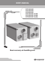
1
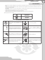
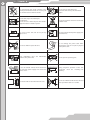
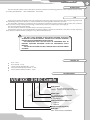
USER’S MANUAL VUT 300 H EC VUT 400 H EC VUT 800 H EC VUT 300 H EC Comfo VUT 400 H EC Comfo VUT 800 H EC Comfo Heat recovery air handling unit 2 CONTENTS Safety requirements Introduction Use Delivery set Designation key Technical data Design and operating logic Mounting and set-up Condensate drain VUT H EC speed controller mounting VUT H EC Comfo control panel mounting Electrical connections Unit control Maintenance Troubleshooting Storage and transportation rules Manufacturer's warranty Acceptance certificate Seller's information Mounting certificate Warranty Card 3 5 5 5 5 6 7 8 14 14 16 16 18 23 24 25 25 26 26 26 27 3 SAFETY REQUIREMENTS • • • • • • Read the user’s manual carefully prior to the operation and installation of the heat recovery air handling unit, hereinafter the unit. Fulfil the user’s manual requirements as well as provisions of all the applicable local and national construction, electrical and technical codes and standards. The warnings contained in the user’s manual must be considered most seriously since they contain vital personal safety information. Failure to follow the safety regulations may result in an injury or unit damage. Read the manual carefully and keep it as long as you use the unit. While transferring the unit control the user’s manual must be turned over to the receiving operator. Symbol legend used in the manual: WARNING! DO NOT! UNIT MOUNTING SAFETY PRECAUTIONS The unit must be disconnected from the power supply prior to every installation or repair operation. The unit must be grounded! The unit must not be operated outside the temperature range stated in the user's manual or in aggressive or explosive environments. Do not use damaged equipment or conductors to connect the unit to power mains. While installing the unit follow the safety regulations specific to the use of electric tools. Unpack the unit with care. Do not change the power cord length at your own discretion. Do not bend the power cord. Avoid damaging the power cord. Do not position any heating devices or other equipment in close proximity to the unit power cord. 4 Do not touch the unit speed controller or the control panel with wet hands. Do not carry out the unit maintenance with wet hands. Do not wash the unit with water. Protect the unit electric parts from water ingress. Use the unit only as intended by the manufacturer. Do not connect a clothes dryer or other similar equipment to the ventilation system. Do not put any water containers on the unit. i.e. flower vases. ON Do not sit on the unit and do not put any objects on it. Disconnect the unit from power supply prior to maintenance. OFF Do not let children operate the unit. Do not damage the power cable while operating the unit. Do not put any objects on the power cable. Keep combustible gases and inflammable products away of the unit. Do not open the operating unit. In case of unusual sounds, smoke disconnect the unit from power supply and contact the service centre. During long-term operation of the unit periodically check the mounting for reliability. Do not block the air duct when the unit is on. Do not let air flow from the unit be directed to the open flame devices or candles. 5 INTRODUCTION This user’s manual includes technical description, operation, installation and mounting guidelines, technical data for the heat recovery air handling unit VENTS VUT … H EC and VENTS VUT…H EC Comfo. USE The heat recovery unit is designed to save heat energy by means of heat energy recovery and is one of the energy saving components used in buildings and premises. The unit is a component unit and is not designed for stand-alone operation. The unit enables continuous air exchange by means of mechanical ventilation in private residences, offices, hotels, cafes, conference rooms as well as recovery of the waste heat energy contained in the extract air to warm up the clean supply air. The unit is designed for wall mounting. The unit is rated for continuous operation always connected to power mains. Transported air must not contain any flammable or explosive mixtures, evaporation of chemicals, coarse dust, soot and oil particles, sticky substances, fibrous materials, pathogens or any other harmful substances. THE UNIT IS NOT INTENDED TO BE USED BY CHILDREN, PHYSICALLY OR MENTALLY DISABLED PERSONS, PERSONS WITH SENSORY DISORDER, PERSONS WITH NO APPROPRIATE QUALIFICATION. ANY OPERATIONS WITH THE UNIT MUST BE PERFORMED ONLY BY PROPERLY QUALIFIED PERSONNEL AFTER THE APPROPRIATE SAFETY BRIEFING. THE UNIT INSTALLATION SITES MUST PREVENT ACCESS BY UNATTENDED CHILDREN. DELIVERY SET Unit − 1 item User’s manual − 1 item Speed controller (for VUT H EC) − 1 item Control panel (for VUT H EC Comfo) − 1 item Power cable (for VUT H EC Comfo) − 1 item DESIGNATION KEY VUT XXX - Х H ЕС Comfo Unit control: _ – R-1/010 speed controller Comfo – control panel with LCD display Motor type: EC – electronically commutated Spigot orientation: H – horizontal Connected air duct diameter: 1 – 150 mm 2 – 160 mm Rated air capacity [m3/h] Unit type: VUT – heat recovery ventilation 6 TECHNICAL PARAMETERS The unit is designed for indoor application with the ambient temperature ranging from +1 °C up to +40 °C and relative humidity up to 80%. The transported air temperature range is from -25 °C up to +50° C. The unit is classified as a class I electric appliance. Hazardous parts access and water ingress protection standard: Unit motors − IP 44; Unit assembly connected to air ducts − IP 22. The unit design is regularly improved, so some models may slightly differ from those ones described in this manual. B1 L L1 B B2 H1 H2 H D UNIT OVERALL DIMENSIONS [mm] VUT 300-1 H EC VUT 300-1 H EC Comfo VUT 300-2 H EC VUT 300-2 H EC Comfo VUT 400 H EC VUT 400 H EC Comfo VUT 800 H EC VUT 800 H EC Comfo 150 160 200 250 ØD B 455 570 840 B1 130 165 215 B2 140 230 390 Н 525 540 660 H1 105 135 160 H2 220 225 295 L 945 925 1010 L1 830 830 890 TECHNICAL DATA Supply voltage, 50/60 Hz [V] 1 ~ 230 Max. unit power [W] 140 210 334 Total unit current [A] 1,2 1,6 2,2 Air capacity [m /h] 300 400 810 RPM [min ] 2300 2600 2860 Noise level, [dB(A)] 24-45 3 -1 30-45 Max. transported air temperature [°C] -25 up to +60 Casing material Aluzinc Insulation Filter: 25 mm min. wool supply G4 extract G4; (F7)* Weight [kg] Heat recovery efficiency [%] Heat exchanger type Heat exchanger material *option 36 67 86 up to 98 83 81 up to 98 Counter-flow Polystyrene 7 DESIGN AND OPERATING LOGIC The unit has the following operating logic: Warm stale extract air from the room flows to the unit, where it is filtered, then air flows through the heat exchanger and is exhausted outside by the extract fan through the exhaust air duct. Clean cold air from outside is moved by the supply fan to the supply filter. Then filtered air flows through the heat exchanger and is moved by the supply filter to the room. Heat energy of warm extract air is transferred to clean intake fresh air from outside and warms it up. Heat recovery technology minimizes heat energy losses, energy demand and operating costs for air heating. The heat exchanger freeze protection function for the VUT H EC unit is implemented with a freeze protection thermostat and for the unit VUT H EC Comfo is implemented with a temperature sensor installed in the exhaust air duct. In case of a freezing danger the supply fan is turned off and the heat exchanger is warmed up with warm extract air flow. To set the thermostat temperature set point set the temperature control knob into a respective position. The recommended thermostat set point is +3 °C (factory setting). VUT 300 H EC SERVICE SIDE VIEW EXTRACT AIR SUPPLY AIR INTAKE AIR EXHAUST AIR Condensate drain pipe Thermostat Supply filter Extract fan Heat exchanger Drain pan Supply fan Extract filter Limit switch Terminal box VUT 400 H EC SERVICE SIDE VIEW VUT 800 H EC SERVICE SIDE VIEW Thermostat 8 VUT 300 H EC Comfo SERVICE SIDE VIEW EXTRACT AIR INTAKE AIR SUPPLY AIR EXHAUST AIR Condensate drain pipe Supply filter Extract fan Heat exchanger Drain pan Supply fan Extract filter Limit switch Control unit VUT 400 H EC Comfo SERVICE SIDE VIEW VUT 800 H EC Comfo SERVICE SIDE VIEW MOUNTING AND SET-UP MINIMUM SERVICE ACCESS TO THE UNIT While mounting the unit provide the minimum service access for service and repair. The minimum service distances from the unit to the walls are shown in the figure below. VUT ... H ЕС VUT ... H ЕС Comfo min 550 mm min 550 mm Service side Service side 9 UNIT MODIFICATIONS The unit service side may be changed for mounting convenience and for keeping minimum mounting and service distances. The instruction on service side change is shown below. Left modification EXTRACT AIR INTAKE AIR Service side SUPPLY AIR EXHAUST AIR Right modification INTAKE AIR EXTRACT AIR Service side EXHAUST AIR SUPPLY AIR SERVICE SIDE CHANGE 1. Dismantling the mounting bracket on the current service side: 1. Loosen the two triangular retaining the bracket. 2. Pull the bracket downwards to withdraw it from the slots. 3. Remove the bracket and tighten the triangular screws. 1 2 3 2. Dismantling the panel on the current service side: 1. Remove 6 screws. 2. Open the back panel and disconnect the ground cable. Remove the back panel. 1 2 10 3. Removing the service panel on the current service side: 1. Remove the 6 triangular screws. 2. Open the panel and disconnect the ground cable. Remove the panel. 1 2 Ground cable 4. Removing the limit switch on the current service side: 1. Remove the spade terminals to detach the limit switch from the wires. 2. Press the fixing lugs to remove the limit switch from the mounting bracket. 3. Remove the two screws that retain the limit switch holder. 4. Remove the holder from the unit. 1 2 3 4 11 5. Mounting the limit switch on the selected service side: 1. Fix the limit switch holder on other side of the unit with two screws. 2. Fix the limit switch in the holder. 3. Take on the spade terminals to connect the limit switch to the wires. 6. Mounting the panel on the selected service side: 1. Connect the ground cable to the service panel on the other side of the unit. 2. Install the panel and fix it with the six triangular screws. 7. Installing the back panel: Install the panel and fix it with six screws. 12 The unit design enables suspended mounting, wall mounting and mounting on the floor. The unit is suspended to the ceiling using belts (not included into the delivery set). For wall mounting use a special mounting bracket and for mounting on the floor use special levelling supports. The mounting instructions are give below. Note: wall mounting is not applicable for the VUT 800 H EC and VUT 800 H EC Comfo units. SUSPENDED MOUNTING 1. Attach the wall mounting bracket to the wall considering the wall material and the unit weight. 2. Install the unit on the mounting bracket. 3. Tighten the triangular fixing screws on the mounting bracket. 13 UNIT MOUNTING ON THE FLOOR 1. Mounting of the unit on the floor is as follows: SUSPENDED MOUNTING The unit is suspended with the belts that must be selected to match the unit weight. The belt must have an opening or a clamp to fix the triangular screws to the unit. The suspended mounting examples are shown below. Rigidly fixed crossbeam Belt fixation place 14 CONDENSATE DRAINAGE The condensate drain pan has a pipe to evacuate the condensed fluid outside the unit. Connect the pipe, U-trap (not included in delivery package) and sewage collection system with metal, plastic or rubber connecting pipes. The pipe slope downwards must be at least 3°. Fill up the system with water before connecting the unit to the power mains! The U-trap must be filled with water at all times during the unit operation. Make sure that the water flows freely into the sewage collection system or otherwise condensed water may build up in the unit during the heat exchanger operation, which may damage the equipment and result in water outflow to the premise. The condensate drainage system is designed for normal operation in premises with air temperatures above 0 °C. If the expected air temperatures are below 0 °C the condensate drainage system must be equipped with heat insulation and pre-heating facilities. min 3° Drain spigot А Drain pipe В U-trap Drain pipe Sewage system А=В ≈ 60 mm VUT H EC SPEED CONTROLLER MOUNTING 1. Disconnect the front panel from the speed controller: 1. Remove the control knob. 2. Remove the retaining nut that fixes the front panel. 3. Remove the speed controller front panel. 1 2 3 2. Loosen the two screws to disconnect the junction box from the speed controller. Disconnect the control cable from the speed controller. Remember the colour marking of the wires and the terminals to enable their correct connection after completing of the speed controller mounting. Screws 15 3. Insert the junction box in the wall. The cable from the delivery set may be replaced with a cable of required length, type 3x0.5 mm2, max. cable length 10 m. 4. Connect the cable to the speed controller following the wiring diagram at page 16. Install the speed controller inside the junction box using screws. 5. Mounting the speed controller front part: 1. Insert the speed controller front panel: 2. Fix the front panel with a washer and a nut. 3. Install the control knob. 4. The speed controller mounting is completed. 1 2 3 4 16 VUT H EC Comfo CONTROL PANEL MOUNTING 1. Use a screwdriver to undo the clips in the lower part of the control panel through the access holes. 2. Remove the back cover. 3. Disconnect the cable from the terminal block. 4. Lay the cable in the wall to the panel installation site. 5. Attach the panel back cover to the wall. 6. Connect the cable to the terminal block. 7. Clip the panel front part in place. ELECTRICAL CONNECTIONS DISCONNECT THE UNIT FROM THE POWER SUPPLY PRIOR TO ANY WORK ON THE UNIT! CONNECT THE UNIT TO A PROPERLY INSTALLED AND GROUNDED SOCKET. ANY TAMPERING WITH THE INTERNAL CONNECTIONS IS PROHIBITED AND WILL VOID THE WARRANTY. The unit is rated for connection to single-phase ac 230 V / 50 Hz power mains. Connect the unit to power mains through the external automatic circuit breaker installed at the power input and integrated into house cabling. The circuit breaker location must provide quick access for emergency shutdown of the unit. The circuit breaker trip current must exceed the current consumption of the unit. The recommended circuit breaker trip current is 2 A and the recommended minimum wire cross section is 0.75 mm2. The given cross sections are for reference only. The wire section selection must be selected in consideration of the wire type, maximum permissible wire heating, insulation, length and installation method, either open installation, cable channel installation or in-wall wiring. Use copper wires only. Ground the unit in compliance with the local electric standards! 17 VUT… H EC SPEED CONTROLLER WIRING DIAGRAM A1 GND CTR +10V 48V 8 7 6 5 +10V CTR GND 4 3 2 X1 1 L N PE (speed controller) L N PE ~230 V 50/60 Hz VUT… H EC Сomfo UNIT WIRING DIAGRAM The unit is designed for connection to 230 V / 50/60 Hz single-phase AC mains. The unit has a power cord with a Euro plug to connect to a grounded IEC 60884-1 compliant socket shown as XP1. The power cord is pre-wired to the X1 terminal block. The VUT H EC Comfo unit enables the following external connection options to the X3 terminal block: • PK contact for automatic fire extinguishing system. While connecting the automatic fire extinguishing system contact remove the jumper between the terminals 1 and 2. In this case the connection relies on a normally closed «dry» contact which opens the unit control circuit on fire-triggered actuation from the central fire alarm system board. • H contact for humidity sensor or CO2 sensor connection Connect the humidity or CO2 sensor to the terminals 3 and 4. The connection relies on a normally closed «dry» contact. Once closed the unit switches to maximum speed. • Y-N, Y-L, Y-C contacts for connection of 3-point control air damper Connect the air damper actuator to the terminals 5, 6 and 7. The same contacts can be used for parallel connection of one more damper. Any extra contacts are connected according to the wiring connection diagram. VUT…H EC Comfo EXTERNAL WIRING DIAGRAM ~230 V 50/60 Гц L N РК to the fire alarm system board PE QF Remove the jumper prior to connecting XP1 Х1 1 2 L N 3 4 5 Y to the external air damper H to the humidity or CO2 sensor Х3 6 “1” “2” “3” 1 PE 2 3 PK 4 5 H 6 N L L 7 Y-C Y-L Y-N VUT… H EC Comfo CONTROL PANEL WIRING DIAGRAM Controller circuit board XT10 XT9 XT14 XT4 39 38 37 36 35 34 33 32 31 30 29 25 24 23 22 4 3 2 1 Connecting cable 4х0,25 mm Control panel circuit board +24 V data2/B data1/A GND Contact number 4 3 2 1 XT1 Wire colour 1 white 2 brown 3 green 4 yellow Damper actuator 18 UNIT CONTROL VUT… H EC CONTROL Air flow is controlled with the P-1/010 speed controller. Set the control knob to a respective speed position to activate the required unit speed. The speed controller view is shown below. SPEED CONTROLLER R-1/010 VUT… H EC Comfo CONTROL The unit is controlled by means of the external control panel and the wireless remote control. 1. Unit Activation \ Deactivation. The unit is activated \ deactivated: from the control panel — with the On/Off button ; From the remote control panel by means of the Unit On/Off button Control panel . Remote control panel Unit on/off Fan speed up Fan speed down C Middle speed activation High speed activation Low speed activation Timer activation/ deactivation Scheduled operation Activation Remote Controller Fan speed control buttons Unit operation mode buttons (see details below) Unit activation/deactivation 19 • Panel Display in OFF mode When the unit is off the control panel display indicates: Room temperature Day Time Deactivated status • . Panel display in ON mode When the unit is on the control panel display indicates: Room temperature Day Time Fan speed status Timer status ; • Timer operation is shown by the • When the timer is switched off the indicator goes on. indicator. 2. Fan speed control. Fan speed control logic: Control panel: Press the high speed); Remote control: Press the middle-high speed); button to increase the speed or press the button to reduce the speed cyclically (i.e. low-middle- button to increase the speed or press the Remote control: Press the button to select low speed, press the activate high speed correspondingly. The control panel display shows the current fan speed status: Glowing indicator — low speed mode; Glowing indicator — middle speed mode; Glowing indicator — high speed mode. button to reduce the speed cyclically (i.e. low- button to select middle speed or press the button to 3. Timer. The timer enables automatic switching of the fans to the maximum speed with automatic reset after a set time period from 20 to 60 minutes. Timer activation / deactivation: Control panel: to activate the timer press and hold the button and then press the button. A single pressing sets the timer to 20 minutes while each subsequent pressing increases the timer setting in 10 minute increments. The maximum timer setting is 60 minutes. The timer indicator displays the timer countdown instead of the current time. To deactivate the timer press and hold the button for 3 seconds. Remote control: to activate the timer for 20 minutes press the button. To deactivate the timer switch the unit off. 4. Heat Exchanger Freezing Protection. If the exhaust air temperature downstream of the heat exchanger falls below +3 °C the supply fan shuts down. When the air temperature rises above the +3 °C, the unit reverts to set operation mode. 20 5. Unit Parameter Setup. CHANGING THE UNIT SETTINGS WILL DISCARD THE FACTORY SETTINGS! FAN SPEED CAN ONLY BE ADJUSTED FROM THE CONTROL PANEL! Fan Speed Setup Mode. At the setup stage each of the low, medium and high speed settings can be attributed a specific supply and extract fan performance. To enter the fan speed setup mode switch off the unit, then press and hold the button on the control panel and hold button for 3 seconds. Upon entering the setup mode the panel display screen will show the and indicators. and buttons. Set the fan speed as necessary using the While the speed stage is being set the display shows the currently selected speed To change the supply fan power press and hold the button to decrease it. Each pressing of the Press the and or button, then press the . button to increase the speed or press the buttons increases or reduces the supply fan power in 1 % increments. button to display the current supply fan speed in % of the maximum air capacity. To change the exhaust fan power press the button to decrease the power. Each press of the Press the , button and while holding it use the and button to increase the power or the buttons increases or reduces the exhaust fan power in 1 % increments. button to display the current extract fan speed. To exit the fan speed setup mode and save the changes press and hold the The remote control cannot be used to adjust the fan speed. button. To revert to the factory settings enter the fan speed setup mode, press the and buttons simultaneously and hold them for 3 seconds. Factory Fan Speed Settings: Low speed 1 — 40 % Middle speed — 70 % High speed — 100 % 21 6. Filter Replacement Indication. When the filters have reached the end of their service life of 3000 hours the operating temperature indicator normally displayed on the control panel is replaced with the indicator prompting filter replacement or cleaning. In case of filter replacement indicator switch off the unit by pressing button and disconnect it from power supply. Replace the filters the according to the sequence given in the «Technical Maintenance» section, page 21. Connect the unit to the power mains and switch it on by pressing the button on the control panel or the (O)) button on the remote control. Then press the and buttons synchronously to reset the motor meter. 7. Date and Time Setup. Switch the unit off. To enter the date and time setup mode press and hold the button, then press the button select the parameter for adjustment by using the While holding the is blinking. The date and time parameters are ordered as follows: 1. Minutes; 2. Hours; 3. Day; 4. Date; 5. Month; 6. Year. Set the required parameter value on the control panel using the To exit the date and time setup mode press the and and button on the control panel. buttons. The parameter being adjusted buttons. button. 8. Scheduled Operation Mode. To activate the scheduled operation mode press and hold the button and then press the button on the control panel. indicator glowing on the display screen. The scheduled operation mode is confirmed by the To deactivate the scheduled operation mode press and hold the button, and then press the button on the control panel. The scheduled operation mode can be activated or deactivated using the button on the remote control. The timer settings will always prevail over the scheduled operation parameters. 9. Scheduled Operation Setup. There are four entries available for each day which may contain the time for unit changeover to a specific fan speed as well as unit turning ON/OFF. To access the scheduled operation settings, switch off the Day Entry number Time button on the control panel or the unit using the button on the remote control. Press and hold the the control panel. Fan speed button, then press the button on 22 To select the scheduled operation setup mode parameters press and hold the select the required parameter. button and use the and buttons to Use the and buttons to set the parameter values. Scheduled operation setup mode parameters: • Entry number — there are four entries for each day. • Week day — day setting. • Fan speed — fan speed setting for the current entry. • Time — time setting for the current entry. To copy the entries to the following day press and hold the Sunday onto Monday is not possible. button, then press . Please note that copying entries from To exit the scheduled operation setup mode press the button on the control panel or the control. A sample schedule programming sequence is given in the table below. button on the remote SAMPLE PROGRAMMING SEQUENCE Entry number 1 2 3 4 Day Start time Mode Start time Mode Start time Mode Start time Mode Mo. 07:00 Speed 2 08:00 Speed 1 17:00 Speed 2 22:00 Speed 1 Tu. 07:00 Speed 2 08:00 Speed 1 17:00 Speed 2 22:00 Speed 1 We. 07:00 Speed 2 08:00 Speed 1 17:00 Speed 2 22:00 Speed 1 Th. 07:00 Speed 2 08:00 Speed 1 17:00 Speed 2 22:00 Speed 1 Fr. 07:00 Speed 2 08:00 Speed 1 17:00 Speed 2 22:00 Speed 1 Sa. 10:00 Speed 2 12:00 Speed 2 17:00 Speed 2 23:00 Speed 1 Su. 10:00 Speed 2 12:00 Speed 2 17:00 Speed 2 23:00 Speed 1 10. Alarms. In case of an emergency the unit switches off while the alarms are displayed on the control panel display. The list of possible alarms is given in table below. ALARM INDICATION Alarm ALARM REASON INDICATOR FAULT HANDLING Short circuit Freezing protection sensor damage Contact the maintenance service. Breakout 23 MAINTENANCE DISCONNECT THE UNIT FROM POWER SUPPLY PRIOR TO ANY MAINTENANCE OPERARIONS. The unit must undergo technical maintenance 3 to 4 times a year. Maintenance includes general cleaning of the unit and the following operations: 1. Filter maintenance. Contaminated filters increase air resistance thus impairing supply air delivery into the premises. The filters should be cleaned as they get dirty, but at least 3-4 times a year. Use a vacuum cleaner to remove the contamination or use a new filter. New filters can be purchased from your Seller. FILTER REMOVAL 1. Remove the six triangular screws. 2. Take off the side panel. 3. Pull the filters to remove. 1 2 3 2. Heat exchanger maintenance (once per year). Даже при регулярном техобслуживании фильтров на блоке рекуператора могут накапливаться пылевые отложения. Для поддержания высокой эффективности теплообмена необходимо регулярно очищать рекуператор. Для очистки рекуператора извлеките его из установки и промойте его теплым водным раствором нейтрального моющего средства, после чего сухой рекуператора вставьте в установку. HEAT EXCHANGER REMOVAL 1. Remove the six triangular screws and take off the side panel. 2. Loosen the three screws of the retaining plate. Pull the plate aside. 3. Pull the heat exchanger to remove. 1 2 3 24 3. Fan maintenance (once a year). Even regular technical maintenance of the filters may not completely prevent dirt accumulation in the fans which reduces the fan capacity and impairs supply air delivery into the premises. Clean the fans with a soft cloth or a brush. Do not use water, aggressive solvents or sharp objects as they may damage the impeller. 4. Condensate system maintenance (once a year). The condensate drain (line) may get clogged with dirt and dust particles contained in the exhaust air. Check the drain line operation by filling the drain pan under the unit with water, clean the U-trap and the drain line, if necessary. Check periodically that the U-trap is filled with water. 5. Intake grille maintenance (twice a year). The supply duct grille may get clogged with leaves and other objects reducing the unit performance and supply air delivery. Check the supply duct grill twice a year and clean it as required. 6. Duct system maintenance (every 5 years). Even regular fulfilling of all the prescribed above maintenance operations may not completely prevent dirt accumulation in the air ducts which reduces the unit performance. The air duct maintenance means periodic cleaning or replacement. TROUBLESHOOTING Possible faults and troubleshooting Fault The fan does not start up during the unit start-up. Possible reasons Fault handling No power supply. Make sure that the unit is properly connected to power mains and make any corrections, if necessary. Motor jam, impeller clogging. Turn the unit off. Troubleshoot the motor jam and the impeller clogging. Clean the blades. Restart the unit. Circuit breaker tripping Overcurrent resulted from short circuit in the Turn the unit off. Contact the service centre. during the unit turning electric circuit. on. Low air flow. Cold supply air. High noise, vibration. Low set fan speed. Set higher speed. Pollution of filters, fans or heat exchanger. Clean or replace the filter, clean the fans and the heat exchanger. Clogging or damage of air ducts, diffusers, Clean or replace the ventilation system components, louver shutters, grille or other ventilation system such as air ducts, diffusers, louver shutters, grilles. components. Extract filter damage. Clean or replace the extract filter. Heat exchanger freezing. Check the heat exchanger for freezing. In case of need shut down the unit and turn it on after the freezing danger is not longer imminent. Impeller soiling. Clean the impeller(s). Loose screw connection in the fans or in the Tighten the fan or casing screw connectionі against casing. stop. No anti-vibration dampers. Water leakage. Install anti-vibration rubber mounts. Clean the drain line. Check the drain line slant, inspect Clogging, damage or wrong mounting of the the U-trap and make sure the drain line is equipped drain pipe. with frost protection. 25 STORAGE AND TRANSPORTATION RULES Store the unit in the manufacturer’s original packing box in a dry ventilated premise at the temperatures from +5 °C up to +40 °C. Storage environment must not contain aggressive vapours and chemical mixtures provoking corrosion, insulation and sealing deformation. Use hoist machinery for handling and storage operations to prevent the unit damage. Fulfil the handling requirements applicable for the applicable freight type. Transportation with any vehicle type is allowed provided that the unit is protected against mechanical and weather damage. Avoid any mechanical shocks and strokes during handling operations. MANUFACTURER’S WARRANTY The manufacturer hereby warrants normal operation of the unit over the period of 24 months from the retail sale date provided the user’s observance of the transportation, storage, installation and operation regulations. Should any malfunctions occur during the unit operation through the manufacturer’s fault during the warranty period the user is entitled to elimination of faults by means of warranty repair performed by the manufacturer. The warranty repair includes works specific to elimination of faults in the unit operation to ensure its intended use by the user within the warranty period. The faults are eliminated by means of replacement or repair of the complete unit or the faulty part thereof. The warranty repair does not include: • Routine maintenance; • Unit installation / dismantling; • Unit setup. To benefit from warranty repair the user must provide the unit, the user’s manual with stamped sale date and the payment document certifying the purchase. The unit model must comply with the one stated in the user’s manual. Contact your Seller for warranty service. The manufacturer’s warranty does not apply to the following cases: • User’s failure to provide the unit with the entire delivery package as stated in the user’s manual or with missing component parts previously dismounted by the user; • Mismatch of the unit model and make with the respective details stated on the unit packing and in the user’s manual; • User’s failure to ensure timely technical maintenance of the unit; • External damage to the casing (excluding external modifications of the unit as required for its installation) and the internal components of the unit; • Alteration of the unit design or engineering changes of the unit; • Replacement and use of the unit assemblies, parts and components not approved by the manufacturer; • Unit misuse; • User’s violation of the unit installation regulations; • User’s violation of the unit control regulations; • Unit connection to the power pains with a voltage different from the one stated in the user’s manual; • Unit breakdown due to voltage surges in the power mains; • User’s discretionary repair of the unit; • Unit repair performed by any non-authorised by the manufacturer persons; • Expiry of the unit warranty period; • User’s violation of the established regulations specific to the unit transportation; • User’s violation of the unit storage regulations; • Wrongful acts against the unit committed by third persons; • Unit breakdown due to circumstances of insuperable force (fire, flood, earthquake, war, hostilities of any kind, or blockade); • Missing seals if provided by the user’s manual; • Failure to provide the user’s manual with the sale date stamp; • Missing payment document certifying the unit purchase. FOLLOWING THE REGULATIONS STIPULATED HEREIN WILL ENSURE A LONG AND TROUBLE-FREE OPERATION OF THE UNIT. USERS’ CLAIMS SHALL BE SUBJECT TO REVIEW ONLY UPON PRESENTATION OF THE UNIT, THE PAYMENT DOCUMENT AND THE USER’S MANUAL WITH THE SALE DATE STAMP. 26 ACCEPTANCE CERTIFICATE Product Type Heat recovery air handling unit VUT ____________ H ЕС VUT ____________ H ЕС Comfo Model Serial number Manufacturing date Is recognized as serviceable. The product complies with the requirements according to the EU norms and directives, to the relevant EU-Low Voltage Equipment Directives, EU-Directives on Electromagnetic Compatibility. We hereby declare that the following product complies with the essential protection requirements of Electromagnetic Council Directive 2004/108/EC, 89/336/EEC and Low Voltage Directive 2006/95/EC, 73/23/EEC and CE-marking Directive 93/68/EEC on the approximation of the laws of the Member States relating to electromagnetic compatibility. This certificate is issued following test carried out on samples of the product referred to above. Assessment of compliance of the product with the requirements relating to electromagnetic compatibility was based on the above standards. Quality Inspector’s Stamp SELLER’S INFORMATION Shop name Address Telephone E-mail Sales date This is to certify delivery of the complete unit with the user's manual. The warranty terms are acknowledged and accepted. Customer's signature Seller’s seal MOUNTING CERTIFICATE Heat recovery air handling unit VUT ____________ H ЕС VUT ____________ H ЕС Comfo has been connected to power mains pursuant to the requirements stated in the present user’s manual. Company name Address Telephone Installation technician's full name Installation date: Signature: This is to certify that the works specific to the unit installation have been performed in accordance with all the applicable provisions of local and national construction, electrical and technical codes and standards. The unit operates normally as intended by the manufacturer. Signature: Installation technician’s company seal 27 WARRANTY CARD Product type Model Heat recovery air handling unit VUT ____________ H ЕС VUT ____________ H ЕС Comfo Serial number Manufacturing date Sales date Warranty period Sales company Seller’s seal ______________________________________________________________________________________________________ ______________________________________________________________________________________________________ ______________________________________________________________________________________________________ ______________________________________________________________________________________________________ ______________________________________________________________________________________________________ ______________________________________________________________________________________________________ ______________________________________________________________________________________________________ _________________________________________________________________________________________________ 2014 V40EN-03