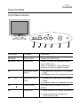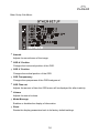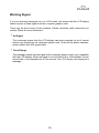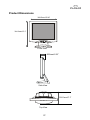
1
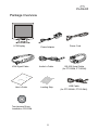
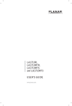
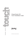
The information contained in this document is subject to change without notice.
This document contains proprietary information that is protected by copyright. All rights
are reserved. No part of this document may be reproduced, translated to another
language or stored in a retrieval system, or transmitted by any means, electronic,
mechanical, photocopying, recording, or otherwise, without prior written permission.
Windows is a registered trademark of Microsoft, Inc.
Other brand or product names are trademarks of their respective holders.
Table of Contents
Usage Notice
Precautions . . . . . . . . . . . . . . . . . . . . . . . . . . . . . . . . . . . . . . . . . . . . . . 1
Introduction
About the Product . . . . . . . . . . . . . . . . . . . . . . . . . . . . . . . . . . . . . . . . . 2
Package Overview . . . . . . . . . . . . . . . . . . . . . . . . . . . . . . . .. . . . . . . . . 5
Installation
Product Overview . . . . . . . . . . . . . . . . . . . . . . . . . . . . . . . . . . . . . . . . . 6
User Controls
Front Panel Controls . . . . . . . . . . . . . . . . . . . . . . . . . . . . . . . . . . . . . . . 14
How to Use the OSD Menus . . . . . . . . . . . . . . . . . . . . . . . . . . . . . . . . . 15
On-Screen Display Menus . . . . . . . . . . . . . . . . . . . . . . . . . .. . . . . . . . . 16
Appendix
Troubleshooting . . . . . . . . . . . . . . . . . . . . . . . . . . . . . . . . . . . . . . .
Warning Signal . . . . . . . . . . . . . . . . . . . . . . . . . . . . . . .. . . . . . . . . .
Product Dimensions . . . . . . . . . . . . . . . . . . . . . . . . . . . . . . . . . . . .
Monitor Specifications . . . . . . . . . . . . . . . . . . . . . . . . . . . . . . . . . . .
Video Modes . . . . . . . . . . . . . . . . . . . . . . . . . . . . . . . . . . . . . . . . . .
Touch Screen Driver Installation . . . . . . . . . . . . . . . . . . . . . . . . . . .
.
.
.
.
.
.
.
.
.
.
.
.
.
.
.
.
.
.
19
20
21
22
23
24
Usage Notice
WARNING - To prevent the risk of fire or shock hazards, do not
expose this product to rain or moisture.
WARNING - Please do not open or disassemble the product as this
may cause electric shock.
Safety and Use Precautions
Follow all warnings, precautions and maintenance as recommended in this User’s
Guide to maximize the life of your unit.
Do:
Turn off the product before cleaning.
Use only a dry soft cloth or clean room wiper when cleaning the LCD panel
surface.
Use only high quality and safety approved AC/DC power adapter.
Disconnect the power plug from AC outlet if the product is not used for a long
period of time.
Don’t:
Do not touch the LCD panel surface with sharp or hard objects.
Do not use abrasive cleaners, waxes or solvents for cleaning.
Do not operate the product under the following conditions:
- Extremely hot, cold or humid environment.
- Areas susceptible to excessive dust and dirt.
- Near any appliance generating a strong magnetic field.
- Place in direct sunlight.
1
Introduction
About Planar’s PT1500M(U), PT1501M(U)
The PT15” products all have a 15” flat panel screen with an active matrix, thin-flim
transistor (TFT), liquid crystal display (LCD).
Features include:
Direct analog signal input
Active matrix TFT LCD technology
1024 x 768 XGA resolution
15” viewable display area
31.5 ~ 60 kHz horizontal scan
56 ~ 75 Hz refresh rate
Auto-adjustment function
Multilingual OSD user controls
VESA DPMS power saving
Kensingston security lock slot
75 mm VESA mount
Durable touchscreen
2
Touch Screen for PT1500M(U)
Resistive for finger and pen interface
Surface : Anti-glare treatment
Interface : Serial (PT1500M), USB (PT1500MU)
Durability : 1,000,000 activations at a single point
Hardness of surface : 4H per ASTM D3363-92
Operating force : Stylus - <25 g (average)
Finger - <50 g (average)
Transmissivity : 85% + / - 2% (typical)
Haze : 5%
Clarity : 80%
Driver : Windows 95/98/Me/NT/2000/XP,
Linux
3
Touch Screen for PT1501M(U)
Capacitive for finger interface
Surface : Anti-glare treatment
Interface : Serial (PT1501M), USB (PT1501MU)
Durability : 225,000,000 touches in a single location
Hardness : Cannot be scratched using any stylus with Mohs' rating of less
than 6.5
Transmissivity : up to 88% at 550 nm
Driver : Windows 95/98/Me/NT/2000/XP,
Linux
MS HID compatible pointing device
4
Package Overview
LCD Display
VGA Signal Cable
User’s Guide
Power Adapter
Power Cord
Audio-In Cable
RS-232 Serial Cable
(for PT1500M, PT1501M)
Landing Strip
USB Cable
(for PT1500MU, PT1501MU)
Touchscreen Driver
Installation CD-ROM
5
Installation
Product Overview
Front View
LCD
Display
Panel
Controls
Speakers
Stand
Rear View
Connector Ports “A”
(Inside the back cover)
Connector
Ports “B”
6
Connector Ports “A”
DC
Power-In
VGA
input
Audio
input
Connector Ports “B”
RS-232
(For PT1500M, PT1501M)
USB
(For PT1500MU, PT1501MU)
Touch Function
7
Kensington Security Slot
The monitor can be secured to your desk or any other fixed object with Kensington
lock security products. The kensington lock is not included.
Kensington Security Slot
8
VESA Mount your monitor
This monitor conforms to the VESA Flat Panel Mounting Physical Mounting Interface Standard which defines a physical mounting interface for flat panel monitors,
and corresponding standards for flat panel monitor mounting devices, such as wall
and table arms.The VESA mounting interface is located on the back
of your monitor.
To mount the monitor on a swing arm or other mounting fixture, follow the instruction included with the mounting fixture to be used.
Slots
75mm
VESA
Mounting
Interface
75mm
Note!
Please select the proper screws!
The distance between the back cover surface and the bottom of the screw
hole is 8mm. Please use a M4 screw.
9
Start your Installation
Remove the Back Cover
Please follow these instructions to remove the cover on the back panel of the LCD
so that you can connect the cables in ”Connector Ports B.”
A
Back Cover
1. To remove the back cover, follow the arrows in Figure A and press with both
your thumbs. The cover should be removed by pressing firmly.
2. Follow the instruction on P.12 (Figure 11.1) to connect the cables in
”Connector Ports B.”
3. Fix the cover back to the LCD. You may also keep the cables in order with the
included cable organizer.
Included Cable
Organizer
Note!
You can place the LCD flat horizontally to make it easier to connect the
cables. Please make sure that you place it on an even surface lest the
LCD should be damaged by scratches or collision.
10
Connecting the Display (Figure 11.1, 11.2)
Figure 11.2 needs to added for the USB port connection.
To setup this display, please refer to the following figure and procedures.
1.
Be sure the computer and monitor are turned off.
2.
Connect the DC power cord to the power connector; plug one end of the AC
power cord into the power adapter, and then the other end into an electrical
outlet (11.1)
3. Connect the VGA signal cable from the display’s VGA input connector to the
15-pin connector of your host computer and tighten the screws (11.1).
4.
Connect the Audio-In cable from the audio input port of your display to the
5.
For the PT1500M and the PT1501M, connect the RS-232 cable from the
Audio-out port of your computer (11.1).
RS-232 port of your display to the RS-232 port of your computer (11.1).
6.
For the PT1500MU and the PT1501MU, connect the USB cable from the USB
port of your display to the USB port of your computer (11.2).
Notice!
To ensure the LCD display works well with your computer, please configure
the display mode of your graphic card to make it less than or equal to 1024 x
768 resolution and make sure the timing of the display mode is compatible
with the LCD display.
We have listed the “Video Modes” of this LCD display in the appendix for your
reference.
11
Figure 11.1
Audio-In
Cable
VGA
Cable
Power Adapter
& Power Cord
12
RS-232
Cable
Figure 11.2
Audio-In
Cable
VGA
Cable
Power Adapter
& Power Cord
13
USB
Cable
User Controls
Front Panel Controls
AUTO
MENU SELECT
No./ Icon
Control
Function
MENU
Menu button
Display the OSD menus
SELECT/AUTO Select/Auto
Select- To select the adjustment items
from OSD menus.
Auto- To activate the “Auto Adjustment”
function to obtain an optimum image.
3
Brightness Minus/
Minus
1.Decreases the brightness of the display
image.
2.Decreases value of the adjustment items.
4
Brightness Plus/
Plus
1.Increases the brightness of the display
image.
2.Increases value of the adjustment items.
Power Switch
Switches on/off the power of the LCD
display.
Power LED
1.Green indicates the display is turned on.
2. Amber indicates the display is in
power-saving mode.
14
How to Use the OSD Menus
1. Press the “Menu” button to pop up the on-screen menu and to select
between the four Main Menus.
2. Choose the adjustment items by pressing the “Select/Auto” button.
3. Adjust the value of the adjustment items by pressing the “3” or “4”
button.
4. The OSD menu will automatically close, if you have left it idle for a pre-set
time.
15
On-Screen Display Menus
Main OSD Menu:
4 Brightness
Choose this function to adjust the brightness of the image.
4 Contrast
Choose this function to adjust the contrast ofthe image.
4 LCD Adjustment
Opens the LCD Adjustment sub-menu where you can adjust the Clock, Phase,
Horizontal Position and Vertical Position parameters.
4 Color Temperature
Opens the Color Temperature sub-menu where you can select the desired Color
Temperature of the image.
4 ECO Mode
Enables or disables the power savings mode.
4 Language
Opens the Language sub-menu where you can select the desired language of the
OSD.
4 Other Setup
Opens the Other Setup sub-menu where you can adjust the Smooth, OSD
Position, OSD Transparency, OSD Time Out, Volume and Mode Message
parameters.
16
LCD Adjustment Sub-Menu:
4 Clock
Minimizes any vertical bars or stripes visible on the screen.
4 Phase
Minimizes any horizontal distortion and clears or sharpens the displayed
characters.
4 H. Position
Changes the horizontal position of the image.
4 V. Position
Changes the vertical position of the image.
17
Other Setup Sub-Menu:
4 Smooth
Adjusts the smoothness of the image.
4 OSD H. Position
Changes the horizontal position of the OSD.
4 OSD V. Position
Changes the vertical position of the OSD.
4 OSD Transparency
Changes the opaqueness of the OSD background.
4 OSD Time out
Adjusts the amount of time the OSD menu will be displayed for after inactivity.
4 Volume
Adjusts the sound volume.
4 Mode Message
Enables or disables the display of information.
4 Reset
Resets the display parameters back to its factory default settings.
18
Appendix
Troubleshooting
If you are experiencing trouble with the LCD display, refer to the following. If the problem persists, please contact your local dealer or our service center.
Problem: No image appears on screen.
4 Check that all the I/O and power connectors are correctly and well connected as
described in the “ Installation ” section.
4 Make sure the pins of the connectors are not crooked or broken.
Problem: Partial image or incorrectly displayed the image.
4 Check to see if the resolution of your computer is higher than that of the LCD
display.
4 Reconfigure the resolution of your computer to make it less than or equal to
1024 x 768.
Problem: Image has flickering vertical line bars.
4 Use “ Clock ” to make an adjustment.
4 Check and reconfigure the display mode of the vertical refresh rate of your graphic
card to make it compatible with the LCD display.
Problem: Image is unstable and flickering
4 Use “ Phase ” to make an adjustment.
Problem: Image is scrolling
4 Check and make sure the VGA signal cable (or adapter) is well connected.
4 Check and reconfigure the display mode of the vertical refresh rate of your graphic
card to make it compatible with the LCD display.
Problem: Vague image (characters and graphics)
4 Use “ Clock ” to make an adjustment. If this problem still exists, use “Phase” to
make an adjustment.
19
Warning Signal
If you see warning messages on your LCD screen, this means that the LCD display
cannot receive a clean signal from the computer graphics card.
There may be two sources for this problem. Please check the cable connections or
contact Planar for more information.
4 No Signal
This message means that the LCD display has been powered on but it cannot
receive any signal from the computer graphic card. Check all the power switches,
power cables, and VGA signal cable.
4 Out of Range
This message means that the signal of the computer graphic card is not compatible
with the LCD display. When the signal is not included in the “Video Modes” list we
have listed in the Appendices of this manual, the LCD display will display this
message.
20
Product Dimensions
382.5mm/15.06”
384.3mm/15.1”
Front View
56.8mm/2.23”
Side View
180.1mm/7.1”
Top View
21
Monitor Specifications
Item
Specification
LCD Module
15-in, active matrix TFT, anti-glare coating,
0.297 mm pixel pitch
Display Size
304 mm x 228 mm
Viewing Angle
Left/Right
60/60 left/right
Up/Down
40/60 up/down
Display Colors
16,777,216 (8bits/color) with FRC
Power Input
100 ~ 240 VAC Full Range, 50/60 Hz
(External AC adapter)
Maximum power consumption
<30W (5W Standby)
Signal Input
Video Signal
RGB positive 0.7VPP, 75ohm
Sync signals
Separate, TTL Level
Line (horizontal) frequency
31.5 kHz to 60kHz
Raster (vertical) frequency
56 Hz ~ 75 Hz
Pixel dot clock
78.75MHz
Recommended mode
1024 x 768 @ 60 Hz
Pedestal tilt
-5 ~ 25 degress
Dimensions (W x H x D)
382.5 x 384.3 x 180.1 mm
Weight
5.1 kgs
Operating Conditions
Temperature
50 ~ 350 C / 410 ~ 950F
Humidity
80% maximum
Altitude
3658m
Storage Conditions
Temperature
-200 ~ 600C / -40 ~ 1400F
Humidity
80% maximum
Altitude
12,193m
22
Video Modes
The monitor supports the following industry-standard combinations of screen resolution and refresh rates. Other combinations are possible, but may require adjustments
to the image.
For the optimal performance, set your computer to a screen resolution of 1024 x 768
at a 60 Hz refresh rate.
Hsync (kHz)
Vsync (Hz)
640 x 350
31.5
70
640 x 400
31.5
70
31.5
60
37.9
72
37.5
75
35.2
56
37.9
60
48.1
72
46.9
75
48.4
60
56.5
70
60
75
31.5
70
34.9
67
35
67
832 x 624
49.7
75
1024 x 768
60.2
75
Display Mode
VGA
640 x 480
SVGA
XGA
800 x 600
1024 x 768
US TEXT
720 x 400
Apple
640 x 480
MAC
23
Touch Screen Driver Installation
Driver Installation for PT1500M: Resistive Touch Screen with RS-232
Serial Connection
Touch driver information is located on the enclosed CD-ROM for the following operating systems: Microsoft Windows R XP, Windows 2000, Windows NT 4.0, Windows
Me, and Windows 9X.
1. Open the CD-Rom.
2. Select the link for your monitor model.
3. The driver file will automatically open.
4. Select the "TW564SR4.exe file.
5. Select "unzip"
6. Double click the "setup.exe" file.
7. Follow the installation instructions.
8. If the touch screen driver does not automatically load, restart the computer
operating system.
Please read "Readme.txt" located in the unzipped file folder for additional information and assistance.
Driver Installation for PT1500MU: Resistive Touch Screen with USB Connection
Please note: These monitors are Microsoft Windows R HID (Human Interface Device)
compatible. No additional software driver is required for general operation of the touch
screen.
A special calibration tool can be installed for improved touch position accuracy. See
Optional MicroTouchTM USB HID Calibration Tool version 7.00 Installation Process
24
Optional Driver MicroTouchTM USB HID Calibration Tool Version 7.00 Installation Process for PT1500MU: Resistive Touch Screen with USB
Connection
Please note: These monitors are Microsoft HID (Human Interface Device) compatible.
The calibration driver is not required for general operation of the touch screen.
This calibration tool is for optimization of touch performance for the touch screen to
meet the 1% TPE accuracy specification.
The following Microsoft Windows R operating systems are supported by this software
driver: Microsoft Windows R 98SE, Me, 2000, and XP.
1. Open the CD-Rom.
2. Select the PT1500MU Calibration Option link.
3. The driver file will automatically open.
4. Follow the installation instructions for the MicroTouch HID Calibration
procedure.
Please read "Readme.txt" located in the unzipped file folder for additional information and assistance.
Driver Installation for PT1501M: Capacitive Touch Screen with RS-232
Serial Connection
Touch driver information is located on the enclosed CD-ROM for the following operating systems: Microsoft Windows R XP, Windows 2000, Windows NT 4.0, Windows
Me, and Windows 9X.
1. Open the CD-Rom.
2. Select the link for your monitor model.
3. The driver file will automatically open.
4. Select the "TW564SR4.exe" file.
5. Select "unzip"
6. Double click the "setup.exe" file.
25
7. Follow the installation instructions.
8. Reconnect the USB cable
9. If the touch screen driver does not automatically load, restart the computer
operating system.
Please read "Readme.txt" located in the unzipped file folder for additional information and assistance.
Driver Installation for PT1501MU: Capacitive Touch Screen with USB
Connection
Touch driver information is located on the enclosed CD-ROM for the following operating systems: Microsoft Windows R XP, Windows 2000, Windows NT 4.0, Windows
Me, and Windows 9X.
If you have a USB cable connection disconnect the cable from the monitor or the
PC before installing the driver.
1. Open the CD-Rom.
2. Select the link for your monitor model.
3. The driver will automatically open.
4. Select the "TW564SR4.exe file.
5. Select "unzip"
6. Double click the "setup.exe" file.
7. Follow the installation instructions.
8. Reconnect the USB cable
9. If the touch screen driver does not automatically load, restart the computer
operating system.
Please read "Readme.txt" located in the unzipped file folder for additional information and assistance.
26
Linux Driver Installation for PT1501MU: Capacitive Touch Screen with
USB Connection
Touch driver information is located on the enclosed CD-ROM. Supported platforms
include: Red Hat R Linux 8.0, Red Hat R Linux 9.0, and SuSE R Linux 8.2 and SuSE
R
Linux 9.0 on Pentium R -compatible CPUs. The following Xfree86 versions are
supported: 4.0.3 and 4.1.0.
1. Open the CD-Rom.
2. Select the "TwLinux5.62.1" folder.
3. Double click the "Readme.txt" file.
4. Follow the driver selection and installation instructions.
Please read "Readme.txt" located in the unzipped file folder for additional information and assistance.
27
Planar Systems, Inc.
Customer Service
Online Support:http://planar.custhelp.com
Email:[email protected]
Tel:1-866-PLANAR-1 (1-866-752-6271)
Hours:m-f, 8am-9pm, Eastern Time
©2004 Planar Systems, Inc. Planar is a registered trademark of Planar
Systems, Inc.
Other brands and names are the property of their respective owners.
Technical information in this document is subject to change without notice.
P/N: 36.57709.003 Rev. A