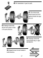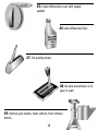
1
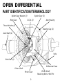
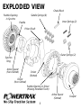
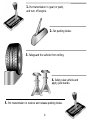
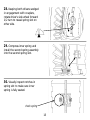
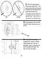
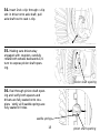
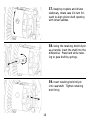
I N S TA L L AT I O N G U I D E
No-Sl i p Tract ion System
TM
Installation Guide
Contents
Page
Open Differential Part Identification & Terminology .........
2
Powertrax No-Slip Differential Exploded View ..................
3
Vehicle Preparation for Installation (steps 1 to 5) .............
4
Removal of Open Differential Parts (steps 6 to 10) ...........
5
Preparation of Parts to be Installed (steps 11 to 13) .........
7
Assembly (steps 14 to 39) ..............................................
8
Verification of Proper Assembly Test (steps 40 to 44) ....... 17
Finish Installation (steps 45 to 49) .................................. 18
Thoroughly read User Manual.
Traction output and resulting handling characteristics of your vehicle will be modified by installation.
Drive carefully and use caution under all on-road and off-road conditions.
OPEN DIFFERENTIAL
PART IDENTIFICATION/TERMINOLOGY
Spider Gear Washer (2)
Ring Gear
Spider Gear (2)
C-Clip (2)
Axle Housing
Thrust Washer (2)
Bearing Cap (2)
Axle Shaft (2)
Yoke
Side Gear (2)
Differential Case
Pinion Shaft
Pinion Gear
2
Pinion Shaft
Retaining Bolt or Roll Pin
EXPLODED VIEW
Paddle Opening
in Synchro
Check Block
Saddle Springs (8)
Inner Springs (2)
Paddle
Pinion Shaft
Outer Springs (2)
Synchro
Ring
Active Spacer
(Non-Slotted)
Driver
(Slotted)
Driver
(Non-Slotted)
Paddle Opening in Driver
(Missing Extended Tooth)
Active Spacer
(Slotted)
3
Coupler
1. Put transmission in gear (or park),
and turn off engine.
2. Set parking brake.
3. Safeguard the vehicle from rolling.
4. Safely raise vehicle and
apply jack stands.
5. Put transmission in neutral and release parking brake.
4
6. Remove Differential cover and
drain fluid. Clean the diff cover and
housing sealing surface.
7. Expose pinion shaft; remove
retaining bolt/roll pin and shaft.
8. Push both axles inward and
remove both c-clips. Remove orings from c-clip grooves on axle
shafts if present.
Note: It may be necessary to
remove wheels and disc brake
calipers.
5
9. Remove both spider gears and
their thrust washers.
10. Pull passenger side axle shaft
out approximately 6”. Remove side
gears and thrust washers.
6
11. Verify gaps in coupler
teeth are aligned with gaps in
synchro ring. Place coupler in a
vise and use an active spacer to
align them if necessary.
12. Apply wheel bearing grease to
driver teeth and spacer.
13. Apply wheel bearing grease to
saddle springs and seat in holes.
7
1
14. Install couplers inside differen-
2
tial case, ring gear side first.
15. Install c-clip on ring gear side
axle shaft only.
8
16. Make sure paddle opening
(widest gap) in ring gear side synchro ring is facing out towards you.
Paddle Opening
17. Insert the non-slotted spacer
into the non-slotted driver. Seat
the spacer paddle at the paddle
opening in driver (missing extended
tooth).
18. Insert driver/spacer as shown,
making sure spacer paddle is facing
out towards you.
9
19. Verify spacer paddle is aligned
with paddle opening in synchro
ring and press driver/spacer down
onto coupler. Driver teeth should
be fully engaged all the way
around.
20. Insert the slotted spacer into
the slotted driver. Seat the spacer
paddle at the paddle opening in
driver (missing extended tooth).
21. Verify paddle opening (widest
gap) in other synchro ring is facing
the back of the differential, away
from you.
Paddle Opening
10
22. Install slotted driver/spacer
making sure that paddle is pointing
away from you toward rear of differential.
23. Verify spacer paddle is aligned
with the paddle opening in synchro
ring and press down on driver/spacer to seat on coupler; driver teeth
should be fully engaged all the way
around.
24. Wedge both drivers in engage-
spring slot
ment with couplers. Rotate driver’s
side wheel forward 1/4 turn to
reveal spring slot.
11
25. Place the two inner springs
inside the two outer springs.
26. Compress inner spring and
install spring assembly into spring
slot.
27. Visually inspect notches in
spring slot to make sure inner
spring is fully seated.
check spring
12
28. Keeping both drivers wedged
in engagement with couplers,
rotate driver’s side wheel forward
1/2 turn to reveal spring slot on
other side.
29. Compress inner spring and
install the second spring assembly
into the second spring slot.
30. Visually inspect notches in
spring slot to make sure inner
spring is fully seated.
check spring
13
31. Check the gap between
drivers using check block. The
narrow side of the block should
fit between the drivers, but the
wider side should not fit.
Go
If driver gap is incorrect, STOP and
call Powertrax Technical Support at
800-578-1020. There may be a
problem with your differential case.
No Go
32. Push passenger side axle shaft
inward through coupler as far as it
will go.
33. Making sure drivers stay
c-clip slot
engaged with couplers, carefully
rotate wheels until c-clip slot is
accessible. Verify c-clip groove on
axle is accessible through c-clip
slots on driver and spacer.
14
34. Insert 2nd c-clip through c-clip
slot in driver onto axle shaft; pull
axle shaft out to seat c-clip.
35. Making sure drivers stay
engaged with couplers, carefully
rotate both wheels backwards 1/4
turn to expose pinion shaft opening.
pinion shaft opening
36. Feel through pinion shaft opening and verify both spacers and
drivers are fully seated onto couplers. Verify all 8 saddle springs are
fully seated in holes.
saddle springs
15
pinion shaft opening
37. Keeping couplers and drivers
stationary, rotate case 1/4 turn forward to align pinion shaft opening
with driver saddles.
38. Using the retaining bolt/roll-pin
as a handle, insert the shaft into the
differential. Press hard while twisting to pass shaft by springs.
39. Insert retaining bolt/roll-pin
into case/shaft. Tighten retaining
bolt firmly.
16
40. Put transmission in gear (or park).
41. Turn driver’s side
wheel forward and hold
against driveline for steps
42 & 43.
HOLD
42. Passenger side wheel
should not be able to rotate
in the same direction.
HOLD
43. Passenger side wheel
should rotate freely in opposite direction.
HOLD
44. Repeat the test for both wheels in
both directions.
17
45. Install differential cover with gasket
sealant.
46. Add differential fluid.
47. Set parking brake.
48. Be sure transmission is in
gear or park.
49. Remove jack stands, lower vehicle, then remove
blocks.
18
822 1002 A
Open Differential
Integral Carrier
C-Clip Version
TM
245 Fischer Ave, Bldg B4, Costa Mesa, California 92626 (800) 578-1020 www.powertrax.com
©1999 Vehicular Technologies and its licensors. All Rights Reserved.