1
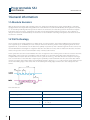
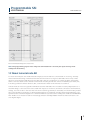
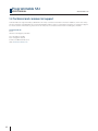
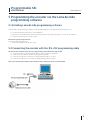
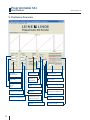
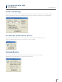
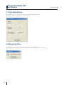
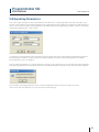
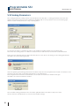
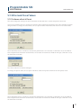
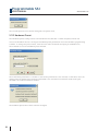
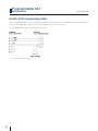
Programmable SSI
MANUAL / USERS GUIDE
Leine & Linde AB
T +46-(0)152-265 00
F +46-(0)152-265 05
[email protected]
www.leinelinde.com
Publication date: 2012-06-01
Programmable SSI
USER MANUAL
www.leinelinde.com
Contents
1 GENERAL INFORMATION
4
1.1 ABSOLUTE ENCODERS
1.2 SSI TECHNOLOGY
1.3 ABOUT LEINE & LINDE AB
1.4 TECHNICAL AND COMMERCIAL SUPPORT
4
4
5
6
2 PROGRAMMABLE ENCODER FUNCTIONS
7
2.1 BASIC ENCODER FUNCTIONALITY
2.2 SCALING FUNCTION
2.3 CODE SEQUENCE
2.4 OFFSET AND PRESET VALUES
2.5 PUSHBUTTON FOR PRESET 1 VALUE (OPTION)
2.6 CODE TYPE
2.7 DATA FORMAT
7
7
8
8
8
8
8
3 DIAGNOSTIC FUNCTIONS
3.1 ALARMS
3.2 WARNINGS
3.3 ENCODER IDENTIFICATION
3.4 OPERATING TIME
9
9
9
9
9
4 PROGRAMMING THE ENCODER VIA THE CONNECTING ELEMENT
10
5 PROGRAMMING THE ENCODER VIA THE LEINE & LINDE
PROGRAMMING SOFTWARE
11
5.1 INSTALLING LEINE & LINDE PROGRAMMING SOFTWARE
5.2 CONNECTING THE ENCODER WITH THE RS-232 PROGRAMMING CABLE
5.3 SOFTWARE OVERVIEW
5.4 RS-232 SETTINGS
5.5 SOFTWARE AND HARDWARE VERSION
5.6 IDENTIFICATION
5.7 OPERATING STATUS
5.8 OPERATING TIME
5.9 OPERATING PARAMETERS
5.10 SCALING PARAMETERS
5.11 OFFSET AND PRESET VALUES
5.11.1 Software offset & Preset
5.11.2 Hardware Preset
11
11
12
13
13
13
14
14
15
16
17
17
18
6 CABLE AND CONNECTORS
6.1 PINNING
6.2 RS-232 PROGRAMMING CABLE
19
19
20
Leine & Linde AB claims copyright on this documentation. This documentation may not be modified,
extended or passed onto to a third party and/or copied without written approval from Leine & Linde AB.
Specifications and content in this document are subject to change without prior notice due to our
continuous efforts to improve the functionality and performance of our products.
3
Programmable SSI
USER MANUAL
www.leinelinde.com
1 General information
1.1 Absolute Encoders
With an absolute encoder each angular position is assigned a coded position value generated by a code disc
equipped with several parallel fine graduations tracks which are scanned individually. On singleturn encoders,
i.e. an encoder producing absolute positions within one revolution, the absolute position information repeats
itself with every revolution. A multiturn encoder can also distinguish between revolutions. The numbers of
unique revolutions is determined by the resolution of the multiturn scanning and repeats itself after the total
resolution is reached.
1.2 SSI Technology
SSI or Synchronous Serial Interface is a digital point-to point interface. It provides unidirectional communication at speeds up to 1.0 MHz by the use of only 4 wires. The absolute position value, beginning with the most
significant bit, is transferred over the data lines (DATA) in synchrony with a CLOCK signal from the control. The
SSI standard data word length for singleturn absolute encoders is 13 bits, and for multiturn absolute encoders
25 bits. The position value is transmitted in Gray or binary code format.
In the quiescent state the clock and data lines are on high level. The current position value is stored on the first
falling edge of the clock. The stored data is then clocked out on the first rising edge. After transmission of a
complete data word, the data line remains low for a period of time (t2) until the encoder is ready for interrogation of a new value. If another data output request (CLOCK) is received within this time, the same data will be
output once again. If the data output is interrupted (CLOCK = high for t > t2), a new position value will be stored
on the next falling edge of the clock, and on the subsequent rising edge clocked out to the subsequent electronics.
Data transfer SSI
Interface
4
SSI
Clock frequency
T
1… 10 μs
Calculation time for Position value
tcal
< 5 μs
Recovery time
t1
t2
0.4 μs
12…30 μs
n
13…25 bit
Programmable SSI
USER MANUAL
www.leinelinde.com
Recommended subsequent electronics
Note: The programming inputs must always be terminated with a resistor (see input circuitry of the
subsequent electronics).
1.3 About Leine & Linde AB
For more than 40 years the Swedish based company Leine & Linde has concentrated on one thing – development and manufacturing of advanced encoders that meet the most rigorous demands. That is why a wide
selection of incremental and absolute encoders with obvious concentration on robust products and quality
down to the last detail can be offered. Leine & Linde encoders provide the utmost in reliability year after year,
in working conditions where vibration, dirt, cold and other harsh environments are common.
Leine & Linde can meet very specific individual customer demands. The encoders are easily adapted, due to a
modular design, to the customer’s exact need with respect to resolution, electrical connections and interfaces,
casings, etc. That is due to the fact that tomorrow’s technology already is used today in Leine & Linde’s product
lines. Leine & Linde concentrate on advanced development of intelligent encoders with integrated ASICs, new
special features and with adaptations to different field bus systems such as CANopen®, Profibus and PROFINET.
This enables us to meet the need for increasingly effective and dependable machines and automation to an
even higher degree.
5
Programmable SSI
USER MANUAL
www.leinelinde.com
1.4 Technical and commercial support
Leine & Linde are represented by subsidiaries in many countries around the world. In addition, there are many
services agencies and distributors located worldwide ready to reply to commercial enquires or technical support.
For more contact information, please visit our web site or contact Leine & Linde in Strängnäs, Sweden.
Leine &Linde AB
Box 8
SE-645 21 Strängnäs, Sweden
Tel: +46-(0)152-265 00
Fax: +46-(0)152-265 05
E-mail: [email protected]
Web: www.leinelinde.com
6
Programmable SSI
USER MANUAL
www.leinelinde.com
2 Programmable encoder functions
2.1 Basic encoder functionality
The figure below gives an overview of the basic encoder functions and how
the functionality is conducted within the encoder.
Physical position
Code sequence
Singleturn resolution
Number of distinguishable revolutions
Basic funtion
Absolute position
Scaling function
Measuring units per revolution
Total measuring range in measuring units
Scaling function control/status
Preset function
Preset value
Offset value
Output position value
2.2 Scaling function
The scaling function converts the encoder’s physical absolute position value by means of software in order to
change the resolution of the encoder. The scaling parameters are securely stored in case of voltage breakdown
and are reloaded at each start-up. Two types of scaling are defined in the PC software, both operates in endless
cyclic mode:
SCALING 1
The parameter ”Scaling factor” is multiplied with the basic resolution. The encoder uses
the Number of revolutions to get the required measuring range.
SCALING 2
The parameters ”units per revolution” and ”revolutions” set the output resolution.
Example of a cyclic scaling:
Units per revolution
Revolutions:
Total number of position
= 1000
= 32
= 32000 (Measuring units per revolution x Revolutions = 1000 x 32)
Note: The offset value is cleared when new scaling parameters are sent to the encoder. After downloading
new scaling parameters the Preset function must be used to set the encoder starting point to absolute
position 0 or to any required starting position within the scaled operating range.
7
Programmable SSI
USER MANUAL
www.leinelinde.com
2.3 Code Sequence
The Code sequence function defines whether the absolute position value should increase during clockwise
(CW) or counter clockwise (CCW) rotation of the shaft encoder seen from flange side. The code direction is
by default set to increase the absolute position value when the shaft is turned clockwise (CW).
Note: The position value will be affected when the code sequence is changed during operation.
It might be necessary to perform a preset after the code sequence has been changed.
2.4 Offset and Preset values
The preset function enables adaptation of the position value from the encoder to a known mechanical reference point of the system. The preset function sets the actual value of the encoder to zero or to the selected
preset values. The preset values are stored in a non-volatile memory, which means that in case of a power
interruption the preset values are reloaded at start-up.
A preset is handled by the encoder in the following way: The encoder reads the current position value and
calculates an offset value from the preset value and the read position value. The actual position value is then
shifted with the calculated offset value.
If scaling is used the preset function must always be used to set the encoder starting point. The preset function
shall always be used after the scaling function. This means that the preset values are entered in the current
measuring unit. The default value for preset 1 and the offset value is zero (0) and for preset 2 the end position.
Note: The preset function should only be used at encoder standstill.
2.5 Pushbutton for preset 1 value (option)
As an option Leine & Linde’s RSA/RHA 608 Programmable SSI encoders can be equipped with a pushbutton.
The function of the pushbutton is to set the encoder position to the predefined preset 1 value. The pushbutton
can for example be used for zero setting of the encoder if the preset 1 value has been set to zero. The pushbutton needs to be activated for at least 1 second before the encoder will be set to the preset 1 value.
For more information, please contact Leine & Linde.
2.6 Code type
The output code can be programmed to be either in Gray or in pure binary format.
2.7 Data format
The data format for transfer of the position values can be programmed to be either synchronous serial
with right alignment or in the 25-bit Tannenbaum structure, allowing it to be adapted to the current
subsequent electronics.
8
Programmable SSI
USER MANUAL
www.leinelinde.com
3 Diagnostic functions
Leine & Linde’s programmable RSA/RHA 608 encoders also offer additional diagnostic functions, such as operating
status (alarm, warnings), encoder identification and operating time.
3.1 Alarms
An alarm output (STATUS) which is output via a separate wire, can be evaluated in the PLC resulting in shorter
dead times. An alarm is set if a malfunction in the encoder could lead to incorrect position values. If an alarm
occurs, the STATUS output signal is set low and the related alarm bit is set to logical high until the alarm is
cleared and the encoder is able to provide an accurate position value. Alarms are cleared automatically when
the functionality is within the specification and the position value correct.
3.2 Warnings
Warnings indicate that tolerances for certain internal parameters of the encoder have been exceeded. In
contrast to alarms warnings do not imply incorrect position values. All warnings are cleared after the status
message is read from the encoder, but if the tolerances are still exceeded, the warning will again be set.
3.3 Encoder identification
With the encoder identification function the user can easily read out the following identification parameters
from the encoder:
•
Type/part number
•
Serial number (base encoder, interface card)
•
Resolution (singleturn, multiturn)
•
Soft- and hardware version
3.4 Operating Time
The operating time monitor stores the operating time for the encoder in operating hours. The operating time is
stored in the non volatile memory at encoder power-down and is reloaded at power-up.
9
Programmable SSI
USER MANUAL
www.leinelinde.com
4 Programming the encoder via the connecting
element
For the RSA/RHA 608 Series of encoders, the following functions can be activated via the programming inputs
of the interfaces by applying the input to a logic high level, i.e +E Volt:
Code sequence
By applying a logic high level (+E Volt) to Pin 2 in the connector the code sequence function is activated and
the direction of rotation is CCW for ascending position values. +E Volt needs to be applied for as long as the
reversed direction of rotation is required.
Note: The position value will be affected when the code sequence is changed during operation.
It might be necessary to perform a preset after the code sequence has been changed.
10
PRESET 1
By applying a logic high level (+E Volt) to Pin 5 in the connector the encoder position is set to the
preset 1 value. +E Volt needs to be applied for t >1 ms in order to change the preset 1 value.
PRESET 2
By applying a logic high level (+E Volt) on Pin 6 in the connector the encoder position is set to
the preset 2 value. +EV needs to be applied for t > 1 ms in order to change the preset 2 value.
Programmable SSI
USER MANUAL
www.leinelinde.com
5 Programming the encoder via the Leine & Linde
programming software
5.1 Installing Leine & Linde programming software
Leine & Linde’s programming software can be downloaded from our website www.leinelinde.com.
1) Download and save the file to your hard drive.
2) Browse to the folder where the file was saved and run “ProgSSI-Setup.msi” to start the installation.
3) Follow the instructions on the screen.
Minimum System Requirements:
PC with at least 486 processor.
• Microsoft Windows 95, 98, NT or XP.
5.2 Connecting the encoder with the RS-232 programming cable
To connect the encoder to the RS-232 programming cable follow the steps below:
1) Connect the RS-232 programming cable to your computers COM-port.
2) Connect the encoder to the RS-232 programming cable.
3) Connect the red wire on the RS-232 programming cable to +E Volt.
4) Connect the blue wire on the RS-232 programming cable to 0 Volt.
Note: The cable length between the encoder and the computer must not exceed 10m.
11
Programmable SSI
USER MANUAL
www.leinelinde.com
5.3 Software Overview
Code format:
-Standard
-Tannenbaum
12
Set the scale
on the Y-axis
Programming Preset
or Offset value
Code sequence:
-CW, CCW,
Transferred
number of
revolutions
Enable or disable hardware preset
Code type:
-Binary
-Gray
Diagram offset of
X-axis
Transferred singleturn
Singleturn resolution
(positions/revolution)
Scaling enabled or
disabled
Total position value:
(Singleturn x Multiturn)
Multiturn resolution
(number of revolutions)
Scaling factor <1 for
reducing the singlseturn resolution
Position value without
scaling
Start testing of the
encoder
Read/Write parameters
from/to encoder
Programmable SSI
USER MANUAL
www.leinelinde.com
5.4 RS-232 Settings
The RS-232 settings can be found under the Communication -> RS232 tab. If necessary change the port
number settings and then click on EXECUTE to perform the changes, or click OK to close the window.
5.5 Software and Hardware Version
The software and hardware version of the encoder can be read from the Encoder data ->
Software and Hardware Version tab. Click OK to close the window
5.6 Identification
The encoder identification can be read from the encoder from the Encoder data ->
Identification tab. Click OK to close the information window.
13
Programmable SSI
USER MANUAL
5.7 Operating Status
The operating status of the encoder can be read from the Encoder data ->
Operating status tab Click OK to close the window.
5.8 Operating Time
The operating time of the encoder can be read from the Encoder data ->
Operating time tab. The time is shown in steps of 0.1 hour. Click OK to close the window.
14
www.leinelinde.com
Programmable SSI
USER MANUAL
www.leinelinde.com
5.9 Operating Parameters
The code output settings can be found under the Encoder data -> Operating parameter tab. Code type, Data
format, Code Sequence and Sequence Mode can be changed from this window. The Sequence mode allows the
user to choose if the encoder’s counting direction should be set by the programming software or by the connecting
element by supplying Pin 2 with +E Volt.
To change the code type, data format and code sequence parameters from Leine & Linde’s programming software,
set the Sequence mode to “Set by software” and then change the Code, Format and Sequence as wanted.
Then click OK to close the window.
Press the Write parameters to encoder button to write the new parameters to the encoder. Once all parameters
have been transferred to the encoder an information window will open. Press OK to close the Information window.
The encoders operating parameters have now been updated and the encoder is ready to be used.
Click on the Test encoder button to test the new encoder settings.
15
Programmable SSI
USER MANUAL
www.leinelinde.com
5.10 Scaling Parameters
The scaling parameter settings can be found under the Encoder data -> Scaling parameters tab. From this
window the Scaling function can be enabled or disabled, and it is also possible to choose the Scaling type,
which is either in units/revolution or by a scaling factor.
To scale the encoder to a specific resolution, just enable the scaling and choose the scaling type.
Then enter the scaling factor or number of units/revolution and revolutions and Click on the OK button.
Please note the warning that the offset value will be set to zero due to the change of the scaling parameters.
Click OK to close the warning window.
After all operating and scaling parameters have been set by the user, the parameters needs to be written to the
encoder. To do this, click on the Write parameters to encoder button.
Once all parameters have been transferred to the encoder an information window will open.
Click OK to close the Information window.
The encoders scaling parameters have now been updated and the encoder is ready to be used.
Click on the Test encoder button to test the new encoder settings.
16
Programmable SSI
USER MANUAL
www.leinelinde.com
5.11 Offset and Preset Values
5.11.1 Software offset & Preset
The offset and preset settings can be found under the Encoder data -> Offset and preset values tab.
Choose the Software choice to change the software offset and preset parameters from Leine & Linde’s programming software. To change the offset value, choose option Define offset direct and enter the new offset value.
Then click Write value to encoder to transfer the parameters to the encoder, or click OK to close the window.
Once all parameters have been transferred to the encoder an information window will open. Click OK to close
the Information window.
The offset value has now been changed.
To change the preset value, choose option Calculate offset from preset and enter the new preset value.
Then click Write value to encoder to transfer the parameters to the encoder, or click OK to close the window.
Once all parameters have been transferred to the encoder an information window will open. Click OK to close
the Information window.
17
Programmable SSI
USER MANUAL
www.leinelinde.com
The encoder position has now been changed to the preset value.
5.11.2 Hardware Preset
The Hardware preset settings can be found under the Encoder data -> Offset and preset values tab.
Choose the Hardware choice to change the hardware preset parameters from Leine & Linde’s programming
software. To change the preset values, enter the new values and check the Input pin enabled boxes.
Then click OK to close the Hardware preset window.
Then click Write parameters to encoder to transfer the parameters to the encoder, or click OK to close the
window. Once all parameters have been transferred to the encoder an information window will open.
Click OK to close the Information window.
The hardware preset values have now been changed.
18
Programmable SSI
USER MANUAL
www.leinelinde.com
6 Cable and Connectors
6.1 Pinning
Function
12 pin EML
17 pin EML
Cable
Description
RS-232TXD
1
1
Blue/Red
RS232 Transmit *)
Code Sequence
2
2
Yellow
Counting direction control
STATUS
3
3
Green
Error signal
RS-232 RXD
4
4
Grey/Pink
RS232 Receive *)
Preset 1
5
5
Black
Preset input 1
Preset 2
6
6
Violet
Preset input 2
+E Volt
7
7
Red
Supply voltage +
Clock
8
8
White
SSI Clock
Clock\
9
9
Brown
SSI Clock inverted
0 Volt
10
10
Blue
Supply voltage 0 volt
Int. shield
NA
11
NA
Internal Shield
B
NA
12
White/Green
Incremental B
B\
NA
13
White/Yellow
Incremental B inverted
Data
11
14
Grey
SSI Data
A
NA
15
Brown/Green
Incremental A
A\
NA
16
Brown/Yellow
Incremental A inverted
Data\
12
17
Pink
SSI Data inverted
* ) Note that the RS232-TxD from the encoder shall be connected to the RS232 –TxD of the communication port
on your PC. The RS232-RxD from the encoder shall be connected to the RS-232 RxD on the communication port
on your PC.
19
Programmable SSI
USER MANUAL
www.leinelinde.com
6.2 RS-232 Programming Cable
The programming cable is used to connect the encoder to a PC serial port for parameter download and diagnostic
readout. The length of the cable is 2 meter with a 0.8 meter power connection.
See the datasheet for part numbers for accessories.
(* = seen from computer side)
20
Programmable SSI
USER MANUAL
www.leinelinde.com
21
+46-(0)152-265 00 www.leinelinde.com
Part no. 686741-01, ver. 1.0
The best encoders are those you never have to think
about. Those that simply do their job – year after year.
Leine & Linde develops and manufactures customised encoder solutions for demanding environments,
advanced measuring systems for accurate feedback
of speed and position.