1
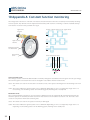
ADS Online
MANUAL / USER’S GUIDE
Leine & Linde AB
T +46-(0)152-265 00
F +46-(0)152-265 05
[email protected]
www.leinelinde.com
Publication date: 2013-01-10
ADS Online
USER MANUAL
www.leinelinde.com
Contents
1 INTRODUCTION TO ADS ONLINE
5
1.1 APPLICATION AREAS
1.2 FUNCTIONAL OVERVIEW
1.3 ENCODER WITH INTEGRATED DIAGNOSTICS
1.4 COMMISSIONING
5
5
6
7
2 FUNCTIONALITY: DIAGNOSTICS AND DATA ACQUISITION
2.1 CONSTANT FUNCTION MONITORING
2.2 MONITORING OF AMBIENT ENVIRONMENTAL PARAMETERS
2.3 DATA ACQUISITION FOR ANALYSIS
3 ENCODER STATUS
8
8
8
9
10
3.1 INTELLIGENT INTERPRETATION OF FAULTS
3.2 CHANNELS FOR COMMUNICATION WITH THE DIAGNOSTICS SYSTEM
3.3 ONLINE COMMUNICATION
3.4 VISUAL OR ELECTRICAL COMMUNICATION
3.5 STATUS INDICATION IN EACH CHANNEL
3.6 CONNECTION OF ELECTRICAL SIGNAL FOR STATUS INDICATION
3.7 ACKNOWLEDGEMENT TO RESET STATUS
10
11
11
11
12
12
14
4 CONNECTION TO PC SOFTWARE
15
4.1 CONNECTION INTERFACES
4.2 START-UP OF THE DIAGNOSTICS SYSTEM
4.3 ON-DEMAND: DIRECT CONNECTION TO A COMPUTER
4.4 LIMITED CONNECTIVITY
4.5 ONLINE: CONNECTION TO A NETWORK
4.6 UNINSTALLING THE PC SOFTWARE
4.7 RESET OF IP SETTINGS
15
15
16
17
18
19
20
5 PC SOFTWARE: INTRODUCTION
5.1 ENCODER OVERVIEW
6 PC SOFTWARE: OVERVIEW
6.1 ENCODER STATUS
6.2 ELECTRONIC LABEL
6.3 CURRENT ENVIRONMENT
6.4 ACCUMULATED VALUES
6.5 PC RELATED INFORMATION
6.6 ACTIVE ALARMS AND WARNINGS
6.7 PREVIOUS ALARMS AND WARNINGS
7 PC SOFTWARE: ANALYSIS
7.1 HISTORY
7.2 ALARMS AND WARNINGS
7.3 RECORDINGS
21
21
22
22
22
23
23
24
24
25
26
26
27
27
3
ADS Online
USER MANUAL
www.leinelinde.com
8 PC SOFTWARE: SETTINGS
29
8.1 IDENTIFICATION
8.2 WARNING LEVELS
8.3 FIRMWARE UPGRADE
29
29
30
9 PC SOFTWARE: HELP
31
9.1 GENERAL
9.2 CONNECTION
9.3 CONTACT
31
31
31
10 APPENDIX A: CONSTANT FUNCTION MONITORING
32
11 APPENDIX B: MONITORING OF AMBIENT ENVIRONMENTAL PARAMETERS
35
12 APPENDIX C: PC SOFTWARE – GRAPHICAL USER INTERFACE
36
13 APPENDIX D: LICENSES
41
14 APPENDIX E: ACCESSORIES
42
This user manual applies to the product ADS Online. The product should not be confused with its predecessor
ADS (ADS Classic). Product functionality differs extensively between the two generations.
Leine & Linde AB claims copyright on this documentation. It is not allowed to modify, extend, copy or hand
over it to a third party without written approval from Leine & Linde AB.
Specifications and content in this document are subject to change without prior notice due to our continuous
strives to improve functionality and performance of our products.
4
ADS Online
USER MANUAL
www.leinelinde.com
1 Introduction to ADS Online
1.1 Application areas
An encoder is often used in large complex machinery such as wind turbines or paper-making machines. It constitutes a central component for speed feedback, with the entire system being dependent on its function, and it
is of the utmost importance that it is reliable at all times.
The encoder is subjected to wear under use and must therefore be replaced at some point. But the exact service life is difficult to predict due to it being highly dependent on parameters in the encoder’s environment.
Temperature, operating speed and vibration are examples of factors that affect service life and that are unique
for each installation. Depending on the ambient environment, an encoder’s service life can consequently vary
from a couple of years to a couple of decades.
A wind turbine is often difficult to access, and in many cases located far out to sea. Unscheduled service is
therefore extremely disadvantageous. High demands are placed on paper mills being in continual operation
and any standstills cost a considerable amount of money. In both of these examples, the goal is to conduct
maintenance during scheduled service, when the entire machine is inspected on a single occasion.
Condition-based maintenance entails service only being conducted as needed. ADS Online offers an advanced
diagnostics system that continually analyses the encoder’s condition and warns for impending faults before
they occur. In this way, service can be performed only as necessary and planned in ample time to avoid unforeseen stops in production.
1.2 Functional overview
The functionality of ADS Online can be summarized in the following points.
• Diagnostics system that constantly monitors the encoder’s key functions, fully integrated into each unit.
• Receive a warning immediately when an impending fault is detected – automatic fault interpretation
determines the seriousness of the fault and categorizes it into various status levels.
• Monitoring of ambient environmental parameters to ensure that the encoder is not subjected to detrimental conditions.
• Continual storage of detailed operational data – analyse trends for vibration, temperature and more.
• Associated PC software with the capability to set custom warning levels and conduct graphical analysis
of the environmental parameters during operation.
• The encoder may be connected to an Ethernet network to provide access to diagnostics and analysis
regardless of your location.
5
ADS Online
USER MANUAL
www.leinelinde.com
1.3 Encoder with integrated diagnostics
An incremental encoder from Leine & Linde always has the basic function of giving electrical pulses when its
shaft is rotated. An encoder equipped with ADS Online has a diagnostics system, separate from this basic function, which constantly monitors that the basic function is operative.
Input for supply voltage.
Output for incremental pulses.
(M23 connector or cable gland)
6
Connection of the diagnostics
system to the PC software.
(M12 connector)
ADS Online
USER MANUAL
www.leinelinde.com
1.4 Commissioning
To install the encoder, mechanically and electrically, the mounting instructions must be followed. This documentation can be found for encoder model XHI 801/803 on www.leinelinde.com.
Electrical installation of the encoder’s basic function is made via an M23 connector or via screw terminals
(depending on the exact encoder variant). The diagnostics function ADS Online is connected via a separate
M12 connector that may be connected to a computer network or directly to a computer.
If the actual encoder variant has connection via screw terminals, its terminal cover is opened upon commissioning for connection of the cable wires. When doing this installation it is important to make sure that also
the ADS Online M12 connector is connected to the PCB of the encoder. This is done by plugging the pending
black connector into the white PCB connector, as seen in the image below.
7
ADS Online
USER MANUAL
www.leinelinde.com
2 Functionality: Diagnostics and data acquisition
ADS Online is a diagnostics system monitoring the encoder’s key functions, but also a system for acquisition of
data from the surrounding environment through a number of sensors. Each encoder has an integrated memory
where detailed data of the encoder’s operating history is stored. Information can be read out either online or
retrospectively through the associated PC software.
2.1 Constant function monitoring
Integrated into each encoder unit is an advanced diagnostics system that continuously checks and verifies the
encoder’s basic functionality. Diagnostics is made on functions like pulse detection, output signal quality and
optics.
Pulse detection
• Resolution error
• Reference pulse not detected
• State transition fault
Optics
• Light unit current
• Light source failure
Output signals
• Faulty output signal
• Low signal level
A detailed description of the functional parameters can be found in Appendix A.
2.2 Monitoring of ambient environmental parameters
The encoder is mounted directly on a motor or generator, situated in the middle of the machine’s actual operating environment. Because this operating environment affects both the encoder’s and machine’s service life,
it is of interest to gain familiarity with the conditions in the encoder’s immediate surroundings.
With ADS Online, the encoder’s function is expanded to encompass several sensors in one. The multi-sensor
constantly reads off the levels for several environmental parameters in its surroundings.
• Vibration
• Shaft speed
• Frequency
• Temperature
• Supply voltage
It also keeps track of the following values accumulated by the actual encoder unit.
• Revolutions (total number generated)
• Time powered
• Time in motion
A detailed description of the ambient parameters and accumulated values can be found in Appendix B.
8
ADS Online
USER MANUAL
www.leinelinde.com
Receive warning of harmful ambient environment
If an environmental parameter reaches levels that are potentially damaging, a warning is sent via all channels.
A warning entails that the encoder is still functional, but that it is subjected to an environment that may damage it. Should actual damage occur in the encoder, the warning goes over to a higher alarm level. But if measures
are taken in time so that the environment returns to an acceptable level, the warning may be acknowledged so
that the encoder can continue in operation.
Set custom warning levels adapted to your machine
The encoder’s ambient environment can be harmful even for other components nearby. ADS Online therefore
offers the opportunity to program custom warning levels for the environmental parameters that are to be
monitored. With this function, you can set levels that are adapted to the limitations on your particular machine, and avoid the risk of prematurely wearing out components.
2.3 Data acquisition for analysis
What is the machine’s environment like where the encoder is installed? Has it changed with time? The PC
software enables graphical analysis of the encoder’s operating conditions over time – observe developments
regarding vibration, temperature, frequency, shaft speed and supply voltage.
History covering the encoder’s entire service life
Study graphs with data collected during the encoder’s entire service life. Have operating conditions changed
with time? Increased vibrations can be a sign that the encoder’s or motor’s bearings are beginning to wear out,
while increased temperature can mean that friction has increased somewhere in the machine and that service
is required. The history function continually stores data for all environmental parameters, all the way back to
the day when the encoder was first put in service.
Saved fault buffer for each deviation
Each time a function deviation is detected in the encoder, all operational and environmental parameters are
automatically logged that applied when the fault occurred. In this way you can later search for the cause of a
fault in the ambient environment that existed when the fault occurred.
Moreover, the encoder stores a fault buffer that contains detailed parameter data with recorded development
from five minutes before each fault occurs to five minutes after. The data is displayed in graphs that enable
careful analysis of machine and environmental behaviour during the period when the fault occurred. By analysing the operational and environmental parameters before a fault was detected, you can draw conclusions
about the reason for the fault and ultimately prevent reoccurrence. Developments after a fault has occurred
subsequently show the consequences it had on the system.
Programmable recordings
The recording function for operational and environmental parameters can even be used to program custom
time intervals for detailed data collection. With the help of this function, you can make recordings during
selected phases of a machine’s operation and analyse the behaviour of the encoder and ambient environment
during various operational phases. In this way, you gain familiarity with the machine and the environment
where the encoder is situated.
9
ADS Online
USER MANUAL
www.leinelinde.com
3 Encoder status
3.1 Intelligent interpretation of faults
An important function in ADS Online is that the system conducts automatic interpretation and analysis of
each detected fault. The analysis determines the seriousness of the fault and sorts it into one of four categories based on the encoder’s condition. The system also provides notification of a recommended measure that
should be taken to prevent problems.
The encoder’s various status levels are indicated by an LED in one of four states.
• Steady green – Normal state, full functionality.
• Flashing green – Warning, risk for fault due to harmful ambient environment. Recommendation to check
the installation and correct deficiencies.
• Flashing red – Serious alarm, impending fault. Replacement of the encoder is recommended during the
next shutdown for service.
• Steady red – Critical alarm, inoperable. Immediate replacement of the encoder is necessary.
Encoder status
Normal state
Steady green
Warning
Flashing green
Serious alarm
Flashing red
Critical alarm
Steady red
Full functionality
Risk of failure
due to harmful environmental conditions
Impending fault
No function
Operating time
By connecting the encoder to the associated PC software, detailed information can be read about each detected
fault, along with data about the condition of the surrounding environment when the fault occurred.
10
ADS Online
USER MANUAL
www.leinelinde.com
3.2 Channels for communication with the diagnostics system
ADS Online sends information about the encoder’s status via several different channels in parallel. This provides extremely flexible connection opportunities – you can always choose communications via the channel
that best suits your application. Do you want information visually, electrically or online?
Visually
Status indication via LED
Electrically
Status indication via signal cable
Online
Detailed data about encoder status
for analysis via PC software
3.3 Online communication
By connecting the diagnostics system online to an Ethernet network, you gain access to the encoder wherever
you may be, worldwide. With the associated PC software, you can read out the encoder’s current status while
operation is underway and conduct detailed analyses of its ambient environment.
3.4 Visual or electrical communication
A more basic connection alternative is to just connect your PC on-demand, in other words, only when you
know that a detected fault has been stored in the encoder’s memory. Each time a fault is detected, the encoder
namely sends a fault indication signal, both electrically via the signal cable, and visually via an LED. A fault
indication signal means that you should connect your laptop to the encoder to read out more detailed information about the fault. The connection is easily made, directly while the machine is in operation.
11
ADS Online
USER MANUAL
www.leinelinde.com
3.5 Status indication in each channel
The three different channels – visual, electrical and online – always show a correlating status. If the encoder
status is changed a fault indication is sent over all three channels. The table below shows how the different
encoder states are presented in each channel.
Status
Online
Digital LED
Visual
Physical LED
Electrical
Wire, status green
Wire, status red
Normal state
Steady green
Steady green
0
1
Warning
Flashing green
Flashing green
0 / 1 (toggling)
1
Serious alarm
Flashing red
Flashing red
1
0 / 1 (toggling)
Critical alarm
Steady red
Steady red
1
0
Not powered
Grey
Off
1
1
1 = +E Volt, 0 = 0 Volt
By connection to the associated PC software, detailed information can be read out for each detected deviation,
together with data regarding the ambient environment condition in the moment of the deviation.
3.6 Connection of electrical signal for status indication
If ADS Online detects an alarm or warning in the encoder, the status will change and an electrical fault indication will be sent via the signal cable. To enable this function connection must be made in the following way.
With four extra wires in the signal cable the exact status of the encoder can always be determined. The wires
named “Status green +” and ”Status green –” can be used to imitate the green states of the encoder LED, while
the wires named “Status red +” and “Status red –“ can be used to imitate the red states. See the table in chapter 3.5 for correlation between the status wires and the encoder LED. The status signal is given by an optically
insulated output which means that the system receiving the status signal can be galvanically separated from
the other electronics. The figure below shows how connection of the status wires can be made, as two separate
circuits for alarms and warnings.
+EV
Status green +
Warning output
Subsequent electronics
Encoder
Status green –
0V
+EV
Status red +
Alarm output
Subsequent electronics
Encoder
Status red –
0V
12
ADS Online
USER MANUAL
www.leinelinde.com
Pin configuration
Function
Screw terminal
M23 connector
Cable
+ E Volt
K
12
Red
0 Volt
H
10
Blue
S00
F
5
Yellow
S00 inv
E
6
Black
S90
D
8
Green
S90 inv
C
1
White
Sref
B
3
Brown
Sref inv
A
4
Violet
Status green +
L
7
Grey/pink
Status green –
M
2
Red/blue
Status red +
N
9
Grey
Status red –
O
11
Pink
Shield
Chassis or G
Chassis
Chassis
Tx +
1
1
1
Rx +
2
2
2
Tx –
3
3
3
Rx –
4
4
4
M12 connector (Ethernet)
Customized models XHI 891 and XHI 893 may have different pinning, please consult encoder label.
13
ADS Online
USER MANUAL
www.leinelinde.com
3.7 Acknowledgement to reset status
By connecting the PC software alarms and warnings can be acknowledged.
The warnings are related to the ambient environment of the encoder, and indicate an external problem. If
actions are taken in time to change the environment to an acceptable level, the encoder is still operational.
Acknowledgement of a warning will therefore reset the encoder status to normal state (steady green).
The alarms may also be acknowledged to indicate that they have been noticed. However, acknowledgment
of an alarm will not reset the encoder status, it will remain on blinking red or red. As an alarm is related to a
serious or critical malfunction in the encoder, the status will continue indicating that the encoder needs to be
replaced.
Normal
state
(steady
green)
Acknowledge
Warning
(flashing
green)
Serious
alarm
(flashing
red)
Critical
alarm
(steady
red)
14
ADS Online
USER MANUAL
www.leinelinde.com
4 Connection to PC software
To read out detailed data about the encoder’s status it may be connected to a computer equipped with the
PC software for ADS Online. The PC software is available upon request to Leine & Linde and is compatible with
Windows XP and Windows 7. The encoder’s diagnostics system may be connected to a network (online) or
point-to-point to a computer (on-demand).
4.1 Connection interfaces
The encoder has two separate connection interfaces, one for the encoder’s basic function (incremental pulses),
and another for the diagnostics system (ADS Online). In this chapter the connection to the PC software is
described.
Input for supply voltage.
Output for incremental pulses.
(M23 connector or cable gland)
Connection of the diagnostics
system to the PC software.
(M12 connector)
4.2 Start-up of the diagnostics system
Every time power is supplied to the encoder the diagnostics system has a start-up time of approximately one
minute. During this time the encoder LED is flashing green with a high frequency. Once the LED stabilizes on
one of the four status levels (steady green, flashing green, flashing red, steady red) the diagnostics system is
functional. Thereby data can be read out via the PC software.
Note that the encoder’s basic function (incremental pulses) is functional also during the start-up time of the
diagnostics system.
15
ADS Online
USER MANUAL
www.leinelinde.com
4.3 On-demand: Direct connection to a computer
The diagnostic system is designed to communicate over an Ethernet network, but direct connection (point-topoint) between encoder and computer can also be made. Suitable connection cables from Leine & Linde are
listed in Appendix E.
Connection can be made during running operation of the encoder, or after it has been dismounted. In the last
case, note that the encoder needs to be powered via the M23 connector or cable gland input.
Establish a direct connection
• Connect the encoder’s M12 connector to the computer’s RJ45 input for network cables.
• Start up the PC software. Make sure the digital LED lights up in the upper left corner (this may take
around fifteen seconds). When the LED lights up connection is established!
If connection does not succeed
If having problems when trying to establish a direct connection, one of the following actions may help.
• Go to the tab Settings and sub tab Identification. Make sure Encoder IP is preset to address 169.254.111.111.
• Test to restart the PC software.
• Test to restart the computer to reset its IP settings (in case they have been automatically altered while
connected to a network).
• Test to restart the encoder by disconnecting and reconnecting the power (wait one minute for the diagnostics system to boot).
• In case the IP address of the encoder has been changed it can be reset to its default address
169.254.111.111. This is done by opening the encoder terminal cover and push the small push-button for
5 seconds (see chapter 4.7).
16
ADS Online
USER MANUAL
www.leinelinde.com
4.4 Limited connectivity
If the message “Limited connectivity...” is active together with a warning triangle in the lower left corner of the
PC software, the computer network settings are blocking parts of the data transfer. This means the encoder
status and current environment values will still be updated, but the detailed alarm/warning descriptions and
history data will not. It may be due to one of three causes, please see detailed description below.
Limited connectivity due to firewall settings
Many computers intended for use in a company network have firewall settings that may block important parts
of the data transfer between the encoder and the computer. Make sure the firewall accepts transfer of the program files ADSDiagnostics and adsonline.exe and that it doesn’t block traffic on ports 69, 161 or 162. If necessary,
use a computer dedicated to communication with devices outside of the company network, where the firewall
settings may be set to a lower safety level.
To alter the firewall settings in Windows, go to Control panel -> System and Security -> Windows Firewall -> Allow a
program through Windows Firewall. Then tick all boxes related to the programs ADSDiagnostics and adsonline.exe.
This will disable potential blocks on the communication with ADS Online.
Limited connectivity due to different subnets
If this message is active the encoder IP and the computer IP are in different subnets. If you are trying to connect over a network, make sure both the computer and the encoder are connected to the same subnet.
Limited connectivity due to SNMP/TFTP port settings
This problem is usually solved by restarting the computer. The ports can also be manually set under Settings
and sub tab Identification, see detailed description below for Configuration of ports.
Configuration of ports
ADS Online communicates via SNMP and TFTP ports. If the actual computer is also used for communication
with other Ethernet devices, some ports may be occupied. Restarting the computer is usually enough to enable
the ports, but it can also be done manually.
The manual configuration of ports will only be visible if there is an active conflict in the port settings. If this is
the case, boxes for setting the ports will automatically appear under Settings and sub tab Identification.
• Make sure the SNMP trap ports are open (UDP port 161 and 162). This port is used to communicate the
encoder status and current environment values.
• Make sure the TFTP port is open (UDP port 69). This port is used to communicate the detailed
alarm/warning descriptions and history data.
• Make sure no other applications are listening to the above ports on your machine. An error will be
displayed on startup if that is the case.
Standard
The default IP address 169.254.111.111 is chosen in accordance with the standard RFC 3927, Dynamic Configuration of IPv4 Link-Local Addresses, in order to allow point-to-point connection.
17
ADS Online
USER MANUAL
www.leinelinde.com
4.5 Online: Connection to a network
One or several encoders may be connected to a network over Ethernet. To make such installation, good knowledge of the actual network is required; the installation should be made by the responsible network technician.
Leine & Linde can supply information about the pre-programmed network settings of the encoder.
All encoders delivered from factory have preset default IP address 169.254.111.111, and the PC software is
preset to connect to that address. If many encoders are connected to the same network, they must be assigned
with different IP addresses.
The first time connection is established to a new encoder unit, its IP address must be entered in the PC software under Settings, Identification, Encoder IP. Once an encoder unit has been connected to the actual PC, it will
be stored and accessible through the list of previously connected encoders, see chapter 5.1.
18
ADS Online
USER MANUAL
www.leinelinde.com
Basic information about the encoder’s network settings
• The encoder is preset to communicate via DHCP. If it is connected to a network it will automatically receive
a random IP address.
• To establish communication via DHCP a network technician must lock the encoder’s MAC address to an IP
address in the actual network. The encoder’s MAC address is unique for each unit and can be read out on
the physical label of the encoder.
• Note that if an encoder unit is replaced for another unit, the position’s IP address must be updated with the
new unit’s MAC address.
• If the encoder is connected outside of a DHCP network it will take on its default IP address which is
169.254.111.111. This may take up to 10 seconds.
• The PC software is preset to communicate with an encoder on the IP address 169.254.111.111. If the encoder
is assigned with a different IP address this must be entered in the PC software.
Web interface
Apart from the PC software there is also a web interface available for the encoder, see Appendix C. The web
interface is opened in a standard web browser and is used to change the network settings of an encoder unit.
To log on to an encoder, enter the encoder’s IP address in the address field of the web browser. The user name
for login is admin, and the password is the encoder unit’s unique serial number (which can be read out on the
physical label).
With the web interface the encoder’s network configuration can be reprogrammed. It can be assigned with a
new IP address, subnet mask and gateway, and also be set to communicate with a fix IP address. To manually
assign a new IP address, first make sure to set the Encoder configuration to Static.
4.6 Uninstalling the PC software
If an upgraded version of the PC software is about to be installed on the computer, any former version must
first be uninstalled. Enter into My computer then Uninstall or change a program and chose ADS Online from the
list.
19
ADS Online
USER MANUAL
www.leinelinde.com
4.7 Reset of IP settings
It is possible to reset all IP settings for an encoder unit to its original mode. Open the terminal cover and press
the small push-button for at least 5 seconds in order to restore all the unit’s IP settings (default IP address will
be 169.254.111.111). Make sure the encoder is powered when doing this.
20
ADS Online
USER MANUAL
www.leinelinde.com
5 PC software: Introduction
With the PC software, online communication with the encoder is possible during operation. This gives constant
access to the encoder’s actual status, as well as information about warnings, alarms and operating conditions
in real time. The analysis function enables graphical display for the history of the encoder’s operating life along
with the possibility to program own time intervals for detailed data acquisition. It is also possible to set customized warning levels for the ambient environment parameters as well as other operating conditions.
The PC software is divided into three main menus; the Overview tab shows the current environmental conditions and possible alarms and warnings; the Analysis tab enables graphical display over the encoder’s history;
the Settings tab enables customized warning levels and more.
5.1 Encoder overview
If the PC software is started when no encoder is connected to the computer, a black menu bar will show up to
the left. In this menu all encoder units that previously have been connected to the actual computer are shown.
By selecting one of the encoders in the list you get access to the information that was available for the encoder
the last time it was connected. Every time an encoder is connected to the PC software all its stored information
is copied to the actual computer’s hard drive.
In this way information about an encoder unit is accessible also when it is offline. Offline information includes
previous alarms and warnings as well as graphical analysis of the unit’s historical operation. Naturally no
updated information is available. In the lower right corner of the PC software you can see the time when the
encoder data was last updated.
With this feature it is possible to temporarily connect to an encoder unit and automatically copy its stored data
to the computer. With this done, the encoder can be disconnected and analysis made offline. The copied data is
stored as files in a folder on the following location on the actual PC:
• Windows 7: C:\Users\Public\Documents\Leine & Linde\ADS Online\Documentation
• Windows XP: C:\Program Files\Leine & Linde\ADS Online\Documentation
The PC software will automatically locate this data for graphical display.
If several encoders are connected online to a network, they will all be visible in this list together with their
current status which is updated every 10 seconds. Please see Multi-connection in Appendix C for reference to the
graphical user interface. In order to see an encoder unit in this list its IP address must be entered manually the
first time. This is done for each unit under the tab Settings and sub tab Identification (see chapter 8.1).
21
ADS Online
USER MANUAL
www.leinelinde.com
6 PC software: Overview
The headings in this chapter refer to graphical elements in the Overview tab of the PC software.
Please see Appendix C for reference to the graphical user interface.
6.1 Encoder status
When connection is established between an encoder and the PC software, the digital LED will light up in the
same state as the physical LED of the encoder. It has one out of five states.
• Green – Full encoder function
• Blinking green – Warning
• Blinking red – Serious alarm
• Red – Critical alarm
• Grey – No connection established between encoder and PC software
6.2 Electronic label
Encoder name
Next to the digital LED, the name of the actual encoder unit is shown. As default the unit’s name is equal to its
serial number (unique for each unit). The name can however be changed, for example to indicate the location
of the machine where the encoder is installed. To choose a name for the encoder unit, go to the tab Settings and
sub tab Identification.
Serial number
The serial number is unique for each produced encoder unit. This is the way to tell one unit from another.
Model
This is the general model description for the encoder. Many variants can be offered within the same model, but
these variants have most technical specifications in common.
Supply voltage
The range of supply voltage that may be connected to the encoder for power.
Output signal
The electrical output interface of the encoder signal.
Resolution
The number of pulses the encoder gives within one revolution.
MAC address
A unique code for each encoder unit, used for identification in a network. The MAC address is fix and cannot be
changed.
IP address
All encoders are delivered with default IP address 169.254.111.111. If the supply voltage is disconnected, this
address will automatically be set again when the encoder is powered. If the encoder is connected to a network
the network will give it a different IP address via DHCP.
Manufacturing date
This date is set in factory when the encoder is produced.
Commissioning date
This date is automatically set the first time the encoder is powered (outside Leine & Linde factory).
22
ADS Online
USER MANUAL
www.leinelinde.com
6.3 Current environment
The current value for each environmental parameter is updated every second.
• Vibration
• Shaft speed
• Frequency
• Temperature
• Supply voltage
See Appendix B for detailed description of each parameter.
6.4 Accumulated values
The encoder continuously updates data for the following accumulated values of the actual unit.
Rotation direction
The current rotation direction of the encoder shaft. Direction expressed as CW (clockwise) or
CCW (counter-clockwise) viewed from the encoder shaft end.
CW rotation
Revolutions
The number of revolutions accumulated during the encoder’s total lifetime.
Time powered
The number of hours that the encoder has been powered since it was first taken in use.
Time in motion
The number of hours that the encoder shaft has been rotating since the encoder was first taken in use.
23
ADS Online
USER MANUAL
www.leinelinde.com
6.5 PC related information
The fields down to the right in view shows information related to the actual computer in use.
IP address
The IP address of the PC in use.
User name
User name for the logged in Windows application. This name is used as signature for acknowledgements of
alarms and warnings.
Encoder time
The encoder has an integrated clock that logs the time of each registered occurrence in the encoder operation.
In this field the current encoder time is shown based on the encoder’s own clock, but expressed in the time
zone of the computer in use.
The PC software automatically detects the time zone of the actual Windows application in use. All time related
data in the PC software is therefore adjusted and expressed according to the actual time zone.
6.6 Active alarms and warnings
When an alarm or warning is detected by the diagnostics system, detailed information about the occurrence
will show up in this field.
A differentiation is made between alarms and warnings in the encoder. The alarms indicate that serious or critical
damage has occurred to the encoder and that it needs to be replaced. The warnings are related to the ambient
environment of the encoder, and indicate an external problem. A warning means there is a risk that the encoder
will get damaged or temporarily give a faulty signal, unless the problem is taken care of.
Please see chapter 3 for the correlation between the alarm/warning type, the encoder status, and the recommended action to be taken.
Warnings
The encoder is constantly logging the values of the environmental parameters described in Appendix B. If a
warning level is passed for one of the parameters a warning indication is sent to the PC software. The encoder
LED will change status to blinking green.
A description of the actual warning is shown in this field, together with the recommended action to be taken.
The value of each environment parameter in the warning moment is also logged.
The warning state means the encoder is still operational, but that it is exposed to an ambient environment
outside of its specification. It means there is a high risk that the encoder will get damaged or temporarily give
a faulty signal, unless the problem is taken care of. If actions are taken in time to change the environment to
an acceptable level, the encoder does not need replacement. If damage occurs the warning state will change to
alarm state.
Acknowledgment of a warning can be made, which means the encoder status will go back to normal state
(steady green), the encoder is still operational.
As long as a warning remains unacknowledged the encoder will not send any new warnings of the same type.
Other warning types than the unacknowledged one, may however occur. Once a warning is acknowledged, also
the same warning type may occur again.
24
ADS Online
USER MANUAL
www.leinelinde.com
Data for warnings are stored in a separate memory area in the encoder’s internal memory. Memory allows data
for 15 warnings. If 15 unacknowledged warnings are stored in the encoder no new warnings will be detected.
But once a warning is acknowledged in the PC software, its memory space is enabled for new future warnings.
An acknowledged warning may therefore be overwritten when a new warning occurs.
If the warning data has been copied to a PC during connection, more than 15 warnings may be visible in the PC
software.
Alarms
If a malfunction is detected in the encoder an alarm indication is sent to the PC software. The encoder LED will
change status to blinking red or steady red (depending on the alarm type).
A description of the actual alarm is shown in this field, together with the recommended action to be taken. The
value of each environment parameter in the alarm moment is also logged.
Acknowledgment of an alarm can be made, but the encoder status will remain on blinking red or steady red. As
an alarm is related to a serious or critical malfunction in the encoder, the LED will continue indicating that the
encoder needs to be replaced.
As long as an alarm remains unacknowledged the encoder will not send any new alarms of the same type.
Other alarm types than the unacknowledged one, may however occur. Once an alarm is acknowledged, also the
same warning type may occur again.
Data for alarms is stored in the encoder’s internal memory. The encoder memory allows data for the 15 first detected alarms, plus one 16th alarm for prioritized critical alarms. Data for alarms cannot be erased, after 15+1
alarms no more alarms will be detected.
Acknowledge
This button is visible in the alarm/warning box when the alarm/warning is active. Click on the button to
acknowledge the alarm/warning. It can be opened again through the list of Previous alarms and warnings.
When acknowledgement is made the actual time and the Windows user name is stored as reference.
6.7 Previous alarms and warnings
This list gives an overview of the alarms and warnings that have occurred to the encoder in the past. It is
possible to open up a historical alarm or warning to read out more detailed information.
25
ADS Online
USER MANUAL
www.leinelinde.com
7 PC software: Analysis
The encoder constantly logs detailed data of its environment. This data can be used to analyse the environment in which the encoder is used. The analysis may serve to get a better understanding of what the system
around the encoder is exposed to.
Note that all data is stored in the encoder’s internal memory. This means it is possible to connect to the encoder and read out data retrospectively, stored in the encoder memory. When connecting to the encoder, the stored
files are automatically copied to the PC. Once transferred, they may therefore be accessed also offline.
The headings in this chapter refer to graphical elements in the Analysis tab of the PC software. Please see
Appendix C for reference to the graphical user interface.
Time ranges
Analysis of the environmental parameters can be made for three different categories.
• History: Data is continuously stored for the encoder life time, last 24 hours and last hour.
• Alarms/warnings: Extra detailed data is stored as a fault buffer every time an alarm/warning is trigged.
• Recording: It is also possible to record extra detailed data during a programmable time interval.
Parameters
Data is available for the five ambient parameters described in Appendix B.
• Vibration
• Shaft speed
• Frequency
• Temperature
• Supply voltage
Overview: Ambient parameters during actual time range
The max, min and mean value for the selected time range is calculated and displayed for quick overview.
Graphical tools
When holding the cursor over the graph area, three tool buttons appear. Their functions permit the user to
Zoom, Scroll in the graph or go back to Start view of the selected time range.
Export data
The data behind any graph can be exported and stored as a file for use with other programs like Excel.
7.1 History
Data for each ambient parameter is constantly recorded while the encoder is powered. Graphical display is
available for each ambient parameter over one of three time ranges.
Encoder lifetime
The time range for encoder lifetime stores data for the maximum and minimum value detected for each day in
the encoder’s lifetime. The graph shows two different lines, one for the maximum values and one for the minimum values detected.
New data is available once every 24 hours. The update is made at midnight GMT time. All time references in
the PC software are however expressed in the local time zone of the actual PC in use.
26
ADS Online
USER MANUAL
www.leinelinde.com
Last 24 hours
The time range for last 24 hours stores data for the maximum and minimum value detected for each hour in the
time range. The graph shows two different lines, one for the maximum values and one for the minimum values
detected.
Last hour
The time range for last hour stores data for the maximum and minimum value detected for each second in the
time range. The graph shows two different lines, one for the maximum values and one for the minimum values
detected.
The data is automatically updated when one full hour has passed. It is also possible to get an update upon
request, by pressing the Update button.
7.2 Alarms and warnings
Every time an alarm or warning is detected, the diagnostics system will automatically start a detailed tracking
of each ambient parameter. Data for the 5 minutes preceding the alarm/warning moment is stored together
with data for the 5 minutes following the same moment. The data is stored at a frequency of ten measuring
points per second.
This detailed data can be graphically displayed for analysis of the ambient conditions during which the fault
occurred. This information can be used to learn more about the actual application in the fault moment and be
used to prevent future faults.
Data for alarms is stored for the rest of the encoder’s lifetime (inerasable). Memory allows data for the 15 first
detected alarms, plus one 16th alarm for prioritized critical alarms.
Data for warnings is stored in a separate memory ring buffer. Memory allows data for 15 warnings. Data for
acknowledged warnings may be overwritten by future warnings.
7.3 Recordings
The record function can be activated during a programmable time interval. The user can specify a time interval
with a start and stop hour to record detailed data.
The data is stored on the encoder’s internal memory. This means it is possible to disconnect the encoder after
programming it and let the recording be made by the encoder offline.
Five recordings can co-exist in the encoder’s internal memory area. When memory is full the first made recording will be overwritten. Before the file is overwritten it will however be copied to the PC’s hard drive (if connected).
Therefore more than five historical recording may be accessible from the time range list.
The maximum allowed time range is 48 hours for each recording. If a longer recording is desired it is possible
to pre-order up to 5 consecutive recordings and thereby get 10 days of continuous data, where the data will be
accessible step by step as the 48 hour part recordings get finished.
Start
Set the time for the desired start moment of the recording.
Stop
Set the time for the desired stop moment of the recording.
27
ADS Online
USER MANUAL
www.leinelinde.com
Update frequency
The possible detection frequency, i.e. the time between each measuring point, is calculated by the PC software.
The frequency is automatically set to 0,01 s, 0,1 s, 1 s or 10 s, depending on how long the selected time interval
is (there is room for 18000 samples in each of the five recording slots). A short programmed time range will give
a high sample frequency, while a long programmed time range will give a low sample frequency.
Name
Type a name that describes the planned recording. When the recording is executed this name appears in the
drop list for time range, where it can be selected for graphical display.
Save
To execute a recording, click on the Save button. Then the recording will appear in the list of Planned recordings,
until it has been executed.
Planned recordings
This list shows the recordings that have been planned but not yet executed.
It is possible to plan up to five recordings. Once a recording is executed it is possible to program a new one in
its place. To delete a planned recording before it is executed, click on the x.
28
ADS Online
USER MANUAL
www.leinelinde.com
8 PC software: Settings
The headings in this chapter refer to graphical elements in the Settings tab of the PC software. Please see
Appendix C for reference to the graphical user interface.
8.1 Identification
Setting Encoder name
As default the encoder unit’s name is equal to its unique serial number. The name can be changed, however,
for example to indicate the location of the machine where the encoder is installed. The name of the actual
encoder unit is shown next to the digital LED.
Setting Encoder IP
This field shows which IP address the PC software will search for when trying to connect to an encoder. Make
sure the IP address of the desired encoder unit is entered here.
When connection has been established one time to a specific encoder serial number, that encoder unit will be
stored in the list of previously connected encoders (see Encoder overview, chapter 5.1). Next time connection is
desired it is enough to choose the right encoder from that list.
Reprogramming the IP address of the encoder unit itself is made through the web interface, see chapter 4.4.
Configuration of ports
The manual configuration of ports will only be visible if there is an active conflict in the port settings. If this is
the case, boxes for setting the ports will automatically appear under this tab.
8.2 Warning levels
Preset warning levels
The ambient in which the encoder is operating exposes the encoder to wear. The ambient parameters are
harmful to the encoder if their value reaches a level that is outside the encoder’s specification.
This list shows the limit values for each ambient environment parameter. The limit values may be different depending on the exact encoder model. They show the range in which the encoder is specified to be operational.
If the ambient goes outside the range of the preset warning levels, the encoder will change status to warning
state. A description of the five ambient parameters is made in Appendix B.
The preset warning levels are always active and cannot be reprogrammed.
Programmable warning levels
In addition to the preset warning levels, the user has the possibility to program own warning levels. These do
not change to preset levels, but co-exist with them and offer additional levels for warning indication.
The programmable levels may for example be used to give warnings at environmental levels that may damage
other sensors or components situated in the system close to the encoder. They may also be used to indicate
overspeed, underspeed or standstill of the shaft.
It is also possible to set warning levels for the accumulated values of the operating encoder (generated number
of shaft rotations, time in motion or time powered).
29
ADS Online
USER MANUAL
www.leinelinde.com
8.3 Firmware upgrade
When new versions of ADS Online are released, it is possible to upgrade an existing encoder with new diagnostics features. This is made by loading new firmware to the encoder’s internal memory. New firmware is distributed by Leine & Linde via e-mail. To ensure that you receive information about future releases you can register
as a user of ADS Online on our website www.leinelinde.com/ads_online.
30
ADS Online
USER MANUAL
www.leinelinde.com
9 PC software: Help
The headings in this chapter refer to graphical elements in the Help tab of the PC software.
9.1 General
Manual
A hyperlink to this document.
Register
When new versions of ADS Online are released it is possible to upgrade an existing encoder with new diagnostics features. To ensure that you receive information about future releases please register as a user of ADS
Online on our website www.leinelinde.com/ads_online.
Send error report
By clicking on this hyperlink you will copy all information from the encoder’s memory and store it as a file on
your desktop. This file can be sent to Leine & Linde for technical support and help to interpret the stored information.
9.2 Connection
Instruction for Ethernet connection and general guide for trouble shooting. See also chapter 4.3-4.4.
9.3 Contact
Leine & Linde offers local technical support in many countries around the world where we have our own personnel. Don’t hesitate to contact us with questions or feedback. Under this tab you find contact information to
all local Leine & Linde offices.
31
ADS Online
USER MANUAL
www.leinelinde.com
10 Appendix A: Constant function monitoring
The image below shows an overview of the basic encoder functions that are constantly monitored by the diagnostics system. Any deviation from expected functionality will result in a warning or alarm. Detailed description follows in text for each possible error type.
Light unit
current
Faulty output signal / Low signal level
S00
S00
Light source
failure
Reference pulse
not detected
Resolution
error
S90
S90
SREF
SREF
State transition fault
S00
S90
11
01 00
10
OK
Error
State transition fault
The change of state at channel S00 and S90 is normally changed in accordance with the green arrows (see image).
The alarm signal is activated if the state is changed in accordance with the red arrows.
Cause: This fault can occur if the encoder is rotated too fast, if the optics is damaged or if the bearings are worn
out.
Status: The status indication given by this error is different depending on if it is a temporary single error or a
reoccurring one. Resulting status can be flashing green, flashing red or steady red.
Resolution error
The counted number of pulses in one revolution is different from the expected. All increments between two
reference pulses are checked, and the resolution must then be the encoder’s resolution or 0. The fault often
occurs in conjunction with State transition fault.
Cause: This fault can occur if the optics are faulty or damaged.
Status: The status indication given by this error is different depending on if it is a temporary single error or a
repeating one. Resulting status can be flashing green, flashing red or steady red.
32
ADS Online
USER MANUAL
www.leinelinde.com
Reference pulse not detected
This is activated if no reference pulse (Sref) is obtained before the ADS system has counted twice the resolution the encoder shall have. The encoder must be rotated through one additional revolution from the point at
which the reference pulse is absent before the fault is activated. This is the case if the encoder is rotated in the
direction that was determined for the first counting pulse after the reference pulse. If the direction of rotation is changed so that counting goes towards 0, and if a reference pulse is absent at 0, the alarm signal will be
activated directly.
Cause: This fault can occur if the optics or the electronics are damaged or if the bearings are worn out.
Status: The status indication given by this error is different depending on if it is a temporary single error or a
repeating one. Resulting status can be flashing green, flashing red or steady red.
Light unit current
Monitoring of the remaining reserve of the scanning LED. The light control adjusts the current to the light
source to keep a constant amount of light for the photodiodes used to detect the movement of the code disc.
Cause: A low level can result from the following reasons:
• Aging of the LED and the photo elements.
• Change in the sensitivity of the photo elements due to temperature.
• Change in the light intensity of the LED due to temperature.
• Change in the feedback resistance of the input amplifier due to temperature.
Status: This error will result in a flashing red status.
Light source failure
Monitoring of the function of the the scanning LED. An alarm is set when the light source has failed and there
is no possibility to detect any movement of the code disc.
Cause: This fault occurs if the electronics are damaged or if the connection to the light source is broken.
Status: This error will result in a steady red status.
Faulty output signal for the incremental signals
The incremental signals internally in the encoder are compared with the signals that are sent out on the cable.
If these signals do not match, the encoder will operate normally internally, but the signal that is sent out from
the encoder will not be correct or will be absent. This error can be detected as long as the encoder speed is
within the frequency range 0-200 kHz (0-100 kHz for output HC-HTL).
Cause: This fault occurs if the electronics are damaged, if the encoder outputs are overloaded or short-circuited,
or if the ambient temperature is too high.
Status: This error is considered an external one, related to the ambient environment. Resulting status will therefore be flashing green.
Faulty output signal for the reference pulse
The reference pulse signal internally in the encoder is compared with the signal that is sent out on the cable.
If these signals do not match, the encoder will operate normally internally, but the signal that is sent out from
the encoder will not be correct or will be absent. This error can be detected as long as the encoder speed is
within the frequency range 0-200 kHz (0-100 kHz for output HC-HTL).
Cause: This fault occurs if the electronics are damaged, if the encoder outputs are overloaded or short-circuited,
or if the ambient temperature is too high.
Status: This error is considered an external one, related to the ambient environment. Resulting status will therefore be flashing green.
33
ADS Online
USER MANUAL
www.leinelinde.com
Low signal level
When too low signal levels are detected from the optics the output gives an error.
Cause: Probable cause of this error is some kind obstruction of the light in the optics.
Status: This error will result in a flashing red status.
ADS system error
Diagnostics system out of order. The incremental signals may be fully functional, but potential errors will not
be detected by ADS Online. The displayed encoder status is not reliable.
Status: This error will result in a flashing green status.
34
ADS Online
USER MANUAL
www.leinelinde.com
11 Appendix B: Monitoring of ambient environmental
parameters
All ambient environmental parameters are sampled with an interval of 0,1 second. In order to generate a warning the actual environment must however exceed the permitted level during a time period of at least 1 second.
Vibration
The vibration is defined as the resultant force of acceleration for three dimensions. It is calculated with the
help of a 13 bit accelerometer scaling 16 g in each dimension. The vibration is sampled internally with a frequency of 3,2 kHz but is presented to the user as the RMS value during the last 1 second. That means that only
continuous vibration is monitored and that instant shocks are filtered out.
The preset warning level is set with the purpose of preventing the encoder from detrimental vibration levels.
The preset warning is given at 100 m/s2, which is half the maximum vibration level that the encoder can stand
for short time periods.
The vibration level can also be used as an indication of commissioning quality. The better the quality of the
installation the longer operating life can be expected from the encoder bearings. An installation of good quality
usually has continuous vibrations below 5 m/s2, but the values depend on several factors in every unique application, for example on the actual shaft speed. The programmable warning levels may be used to indicate if
the commissioning quality is good enough for continuous use in the actual application.
Shaft speed
The speed of the rotating encoder shaft, expressed in revolutions per minute (unit rpm). The preset warning
level is set to 6000 rpm.
Frequency
The electrical frequency, defined as incremental pulses per second (unit Hertz). The preset level is set to 300
kHz, but the recommended frequency may be limited by the length of the transmission cable in use.
Temperature
The encoder’s operating temperature is detected within the range -60°C to +195°C. The monitored temperature is measured on the encoder PCB, which is approximately +20°C above the ambient temperature when the
encoder is in operation. Heat is generated by the encoder’s electronics as well as by the friction of the rotating
bearings.
The warning level is set to +100°C which is the maximum internal temperature for which the encoder has been
verified.
Supply voltage
The displayed supply voltage shows what voltage is supplied to the encoder. This gives the real voltage level at
the encoder end of the cable, after potential voltage drops in the supply cable.
Depending on the exact model, the encoder is specified for operation within the range of 9-30 Vdc or
4,5-5,5 Vdc.
35
ADS Online
USER MANUAL
www.leinelinde.com
12 Appendix C: PC software – graphical user interface
Overview tab:
36
ADS Online
USER MANUAL
www.leinelinde.com
Analysis tab:
37
ADS Online
USER MANUAL
Settings tab:
38
www.leinelinde.com
ADS Online
USER MANUAL
www.leinelinde.com
Multi-connection:
39
ADS Online
USER MANUAL
Web interface:
40
www.leinelinde.com
ADS Online
USER MANUAL
www.leinelinde.com
13 Appendix D: Licenses
ADS Online has been developed with support of several third party tools using open source licenses.
• GPL
o uClinux environment and utilities
o Linux kernel
o BusyBox
o Boa web server
o dhcpcd
o mtd-utils
o inetd
o init
• LGPL
o uClibc
• OpenSSL licence, SSLeay license
o OpenSSL
• Portmap license
• Telnetd license
• Sash license
• Net-snmp license
• Zlib license
Detailed license descriptions are delivered as files with the PC software and can be found in the folder where
the PC software is installed.
41
ADS Online
USER MANUAL
www.leinelinde.com
14 Appendix E: Accessories
42
Part number
Description
01209179
Power supply for demo use
AC/DC adapter 24 Vdc, 3.2 m cable for terminal connection in the encoder end
800480-01
Connection cable – encoder to PC
Ethernet cable M12-RJ45, 2 meters
824713-01
PC software
USB memory with installation file for program setup
ADS Online
USER MANUAL
www.leinelinde.com
43
+46-(0)152-265 00 www.leinelinde.com
Part no. 828010-01, ver. 2.1
The best encoders are those you never have to think
about. Those that simply do their job – year after year.
Leine & Linde develops and manufactures customised encoder solutions for demanding environments,
advanced measuring systems for accurate feedback
of speed and position.