1
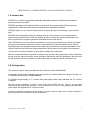
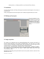
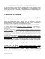
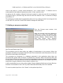
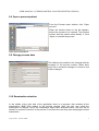
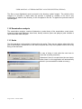
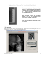
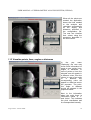
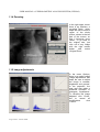
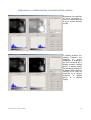
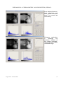
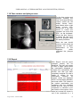
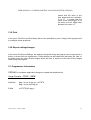
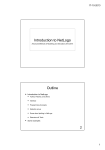
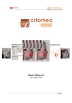
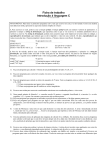
USER MANUAL of CEPHALOMETRIC ANALYSIS SYSTEM (CEPHAS)
User Manual
Cephalometric Analysis System
Version 1.0.0
Jorge Correia – FEUP - INEB
1
USER MANUAL of CEPHALOMETRIC ANALYSIS SYSTEM (CEPHAS)
Cephalometric Analysis System (CEPHAS)
Issue:
15th June 2002
Contents
1. Introduction
2. Configuration
3. Installation
4. Starting up the program
5. Image acquisition
6. Setting values and requirements
7. Adding a new patient
8. Open a process/patient
9. Change process data
10. Examination selection
11. Examination analysis
11.1 Scale
11.2 Landmark
11.3 Visualize points, lines, angles or distances
11.4 Zooming
11.5 Image adjustments
11.6 Face contour and pharynx
12. Report
13. Export settings/images
14. Print
15. Programmer information
Jorge Correia – FEUP - INEB
2
USER MANUAL of CEPHALOMETRIC ANALYSIS SYSTEM (CEPHAS)
1.0 Introduction
CEPHAS is a software application specifically designed to perform Cephalometric analyses,
quickly and easily prompted.
CEPHAS translates each individual value recorded into its corresponding clinical meaning; it
integrates the landmark points entered, and generates a detailed evaluation.
CEPHAS allows you to conduct Cephalometric analyses directly from scanned x-rays saved to
disk.
CEPHAS will automatically guide you step-by-step as to the points to click, and generates a
written summary description. When the guided process to locate the individual landmarks has
been completed, the program generates a detailed and accurate report.
With CEPHAS the user will enter the landmarks on a previously scanned x-ray, with the program
guiding the user always during the analysis. A determination of the scale factor will be also an
important part of the program, because this value will be needed for a correct presentation of the
results in the final report that will be generated when all the parts of the analysis are completed.
In this manual, the term landmark or point will be used with no distinction.
NB: the manual has been purposely compiled to be concise; the programmer advises that after
having read the manual through, users familiarise themselves with the application using the tool
tip text (position the mouse pointer over the button that you want to receive information on).
2.0 Configuration
The minimum system setup requirements are: Pentium III with 256 MB RAM.
A computer with a faster processor and more memory is recommended (for instance: Pentium IV
1700 MHz processor with 512MB RAMBUS).
To optimise image display, a 17” monitor with good quality video card is advised, but 19’’ monitor
is optimal.
Set the screen resolution to 800 x 600 pixels and 65,536 colours. This is an important
requirement, because if the resolution is too low problems will occur in the graphical interface due
to the text in the application as a font size fixed.
In order to make the acquisition of the x-rays, a scanner must be used, and in order to perform a
good acquisition the scanner must be transmissive.
Jorge Correia – FEUP - INEB
3
USER MANUAL of CEPHALOMETRIC ANALYSIS SYSTEM (CEPHAS)
3.0 Installation
Insert the CD and double click Setup, following the instructions that will appear on the screen, to
install CEPHAS.
Clearly, the programmer reserves the right to edit or modify the program without prior notice.
4.0 Starting up the program
Once the installation is done,
and Windows is running, set
the screen resolution to 800
x 600 pixels, click Start C >
CEPHAS and the window
shown here will be displayed
(Menu).
5.0 Image acquisition
The images to be elaborated must be captured beforehand with a scanner and saved in a
directory created specifically for the purpose (\CEPHAS\images). The name given to an image
must not exceed 50 characters (including spaces path and extension), given that longer names
could provoke errors. The protocol to name the image is indicated as follows:
<process numb>_<acquisition date>_<acquisition order in present day>. <extension of capture>.
So an examination made in 26/01/2002 for the process 1234 and being the third examination to
this process in the same day and saved in BMP format, should have the name
1234_26012002_3.BMP.
Note that the month being January still need to have the zero present, without it, and error in the
application will occur.
Jorge Correia – FEUP - INEB
4
USER MANUAL of CEPHALOMETRIC ANALYSIS SYSTEM (CEPHAS)
The best solution will be to capture an 18-20 cm square on the x-ray with the scanner set at a
resolution of 150 dpi, then save the images as bitmaps (BMP’s) or JPG’s. It is advisable to carry
out some trials first in order to adapt results to the hardware currently being used, in order to set
up an operating standard that will not require any further modification. A resolution of 75 dpi would
be enough but to notice some important landmarks 150 dpi will be better.
6.0 Setting values and requirements
The file ‘cephas_config.txt’, (this file can be found in attachment) in the main root (\CEPHAS),
contains all the information about the points, distances and angles measured in the application.
The current list has 33 points, 14 lines, 20 angles and 7 distances.
After the user finishes marking points in the x-ray (points that are defined in the file), the
application determines angles and distances, that are also defined in the file. The importance of
the contents of this file is crucial to the correct execution of the analysis.
If it’s needed to add more points, distances or angles, the following protocol as to be followed.
The syntax to add a new point is: ‘P<number> - <symbol>, <description>.’. To add the point ‘X’
with description ‘Xpto’ you will add next to the line that contains P34: ‘P35 - X, Xpto.’. The letter P
refers to a point.
The syntax to add a new line: ‘L<number>,<number of first point>,<number of second point> <symbol>, <description>.’. To add the line ‘X-Y’ with description ‘Xpto to Ypto’ you will add next to
the line that contains L17: ‘L18,3,8 – X-Y, Xpto to Ypto.’. The letter L refers to a line. Must be sure
of the number of each point in the point list to draw a correct line. Because of this point number
cannot be changed, and when adding point, lines, angles, or distances, always add to end of the
corresponding list.
The syntax to add a new angle: ‘A<number>,<number of first point>,<number of second
point>>,<number of third point>,<number of fourth point> - <symbol>; <description> (<mean
value>/<deviation>).’. To add the angle ‘Xpto’ with description ‘Xpto angle’ you will add next to the
line that contains A21: ‘A22,1,8,3,14 – Xpto, Xpto angle (90/3).’. The letter A refers to a angle.
The line with the points 1-8 and with line 3-14 describes the angle. For further analysis the mean
value and it’s acceptable deviation is needed for better information and conclusions. When a
deviation is not needed just insert in the place of ‘(<mean value>/<deviation>).’ the ‘(<mean
value>).’. Since an angle is defined by two lines, each one defined itself by two points, we have
then four points. Thus the meaning of 1st , 2nd, 3rd and 4th point is to define the first and the
second lines that define the angle.
The syntax to add a new distance: ‘D<number>,<number of first point>,<number of second
point>>,<number of third point> - <symbol>; <description> (<mean value>/<deviation>).’. To add
the distance ‘Xpto’ with description ‘Xpto distance’ you will add next to the line that contains D4:
‘D5,1,8,9 – Xpto, Xpto distance (90/3).’. The letter D refers to a distance. The distance is
described throw the distance of the point 9 to the line 1-8. If only want the distance between two
points just put a zero in the third point. For further analysis the mean value and its acceptable
deviation is needed for better information and conclusions. When a deviation is not needed just
Jorge Correia – FEUP - INEB
5
USER MANUAL of CEPHALOMETRIC ANALYSIS SYSTEM (CEPHAS)
insert in the place of ‘(<mean value>/<deviation>).’ the ‘(<mean value>).’. A distance can be
measured throw the distance between two points, or from a point to a line.
As backup the file ‘cephas_config.bak’ have been created, so when the main file is changed do
not forget to save it, and also copy the same file with the extension ‘.bak’. A comment is always
preceded by ‘%’.
This settings are loaded when the application starts, but if you change it while it’s running just click
on the menu File, and click ‘Load Points’ and the changes will take effect.
7.0 Adding a new process/patient
From the Process menu window, click
"New process".
When the process input form appears to
enable you to insert a new patient's data,
the following ten fields must be completed:
Process Number, Patient Name, Birth
Date (Day, Month, Year), Address,
Location, Post Code, Sex, Phone Number.
New Process/Patient Input Form
This procedure must be done before any adding of examinations to the process. When this
procedure is finished, the program itself will look for the examination and will present to the user
all the files found ready to be analysed.
The processes are introduced in a database generated in the application where there are
structures that contain other structures. A patient has a structure with all its personal data, and
this structure itself has an array of structures corresponding to the number of examinations added
to the process. This final structure has all the information necessary to the analysis about the
examination (angles, distances, points marked, surfaces, etc.).
It will be impossible to move to any other window if these obligatory fields have not been filled out,
therefore it is advisable to click "Ok" only when these data do actually have to be inserted.
To cancel a patient input form, click “Cancel” on the patient input form.
Jorge Correia – FEUP - INEB
6
USER MANUAL of CEPHALOMETRIC ANALYSIS SYSTEM (CEPHAS)
8.0 Open a process/patient
From the Process menu window, click "Open
process".
When the window shown to the left appears,
select the process to be opened. The process
number and the patient name identify it. Click
‘Open’ to visualize the process.
Open a process/patient
9.0 Change process data
The fields are all possible to be changed with the
exception of the process number. When done
press Ok to accept the changes or Cancel to exit
without changes.
10.0 Examination selection
In the middle of the right side of the application there is a popmenu that contains all the
examinations (BMP files) relative to the process opened. Here the user may select the
examination to analyse, and if this examination hasn’t been analysed before, the user will be
asked if he wants to include it in the process. From there the user may start analysing the select
examination.
Jorge Correia – FEUP - INEB
7
USER MANUAL of CEPHALOMETRIC ANALYSIS SYSTEM (CEPHAS)
The files (x-rays digitalized) must be stored in the directory called ‘images’. The refresh of the
images of a process is made when the process is opened or created, so for that if any
examination is added to the directory, it will not appear in the list. To appear the process must be
opened again.
11.0 Examination analysis
The examination analysis, consist of determine a scale factor of the examination, mark points,
measure angles and distances, draw lines, identify contours (face and pharynx) and visualize a
report about the data analysed.
11.1 Scale
The first operation in the analysis is determining the scale. There are two options when doing this
part of the analysis: existence of a ruler scale, acquired with x-ray of the patient head or the x-ray
being in the real scale.
In case of being in real scale the user have to
insert the scanning resolution.
Otherwise if there is a scale factor the user has to
either insert it or the application will automatically
detect it (recommended for better accuracy)
Jorge Correia – FEUP - INEB
8
USER MANUAL of CEPHALOMETRIC ANALYSIS SYSTEM (CEPHAS)
When selected the process of detection of scale
factor, the user must draw a rectangle that
encloses all the ticks of the scale with a rectangle
in the exact place of the scale and intersecting all
the 11 points of the scale, corresponding to the
five centimetres of the scale.
Note: The number of traces and the distance
between all the ticks may be changed, in the
menu ‘Options’-‘Settings’-‘Scale Factor’.
As the scale factor as been detected, the process
may continue.
11.2 Landmark
When the user starts marking the points, they are asked one by one indicating the next to be
marked bellow the Patch, and its corresponding description.
Jorge Correia – FEUP - INEB
9
USER MANUAL of CEPHALOMETRIC ANALYSIS SYSTEM (CEPHAS)
When all the points are
marked the application
draws the lines needed
to the analysis and
calculates automatically
all the angles and
distances specified in
the configuration file.
The user can visualize
their values using the
procedure described in
the next section.
11.3 Visualize points, lines, angles or distances
In
the
pop
menu
‘Displaying’ the user may
chose what information he
wants to see: points, lines,
angles or distances. In
case of points or lines, the
selected one will appear in
a different colour from the
others. In case of an angle
or
a
distance
the
corresponding value will
appear in a little box next to
the popmenu. The point,
line, angle or distance
should be selected in the
popmenu bellow.
Next to the information
about the point there is
information called ‘X’, ‘Y’
and ‘Value’. This indicates
the pixel coordinates and
its correspondent intensity.
Jorge Correia – FEUP - INEB
10
USER MANUAL of CEPHALOMETRIC ANALYSIS SYSTEM (CEPHAS)
11.4 Zooming
In the right upper corner
there is an interface, a
so-called Patch, which
helps the user to zoom a
region of the whole
picture, shown in the left
part of the screen, so
that it becomes more
visible. To go back to
the original size, just
click out of any image
with the right mouse
button
and
select
‘Original Zoom’.
11.5 Image adjustments
In the menu Options,
there is an option called
‘Image Adjustments’ that
helps the user to adjust
the image in contrast,
brightness and gamma.
In the popmenu, the
user may also make a
threshold operation or
histogram equalization.
To visualize the image
adjusted click ‘Close’,
but
to
cancel
all
modifications
click
‘Cancel’.
Jorge Correia – FEUP - INEB
11
USER MANUAL of CEPHALOMETRIC ANALYSIS SYSTEM (CEPHAS)
Brightness is an attribute
of visual perception in
which a source appears
to emit a given amount
of light.
In display systems, the
relation between the
intensity
of
colour,
brightness, or shading of
an area occupied by a
display element, display
group, or display image
on the display surface of
a display device and the
intensity of an area not
occupied by a display
elements,
a
display
group, or a display
image.
Jorge Correia – FEUP - INEB
12
USER MANUAL of CEPHALOMETRIC ANALYSIS SYSTEM (CEPHAS)
Some devices have nonlinear behaviours, and
what gamma correction
does is to correct that
non-linearity.
Histogram equalization
is
obtaining
the
maximum variation of
the image histogram,
resulting by that a better
contrasted image.
Jorge Correia – FEUP - INEB
13
USER MANUAL of CEPHALOMETRIC ANALYSIS SYSTEM (CEPHAS)
11.6 Face contour and pharynx area
For the face contour and
pharynx marking, the
user first traces the face
contour points the left
button mouse clicks,
and finishes with a right
button mouse click.
During this, if the user
wants to cancel the
operation he must click
ESC, on the keyboard.
When the face contour
is traced, the user must
trace the pharynx using
the same procedure.
Note: the user should
mark as much points as
possible, for a better
performance
of
the
algorithm,
which
estimates the pharynx
area.
12.0 Report
Click ‘Report’ and the report
(example shown) will be
displayed. The user may chose
to view a single report about
the examination displayed or
compare this examination with
another one that has been
completely analysed. For that a
listbox is shown for the
examination
selection.
All
program values are displayed
and it’s corresponding deviation
and mean value. The values of
the patient examination are
compared with the standard
values and the result of this
comparison is showed in the
last column of the report. If the
value isn’t normal it’s shown in
red. If the conclusion is +, it
Jorge Correia – FEUP - INEB
14
USER MANUAL of CEPHALOMETRIC ANALYSIS SYSTEM (CEPHAS)
means that the value is one
time bigger than the deviation,
if it’s ++ , it means that the
value is two times bigger, if it’s
five times or more bigger than
deviation it’s shown >>.
13.0 Print
In the menu File>Print and Print Setup there is the possibility to print a image of the program and
to configure printer properties.
14.0 Export settings/images
In the menu File>Export Settings, the settings configured during the program can be exported to a
binary (or a text file to be viewed later). These settings can be loaded from the binary file, later. In
the same menu the option Export Images allows the user to export to a file some of the images
used during the program.
15. Programmer information
CEPHAS is a software application designed, created and distributed by:
Jorge Correia – FEUP - INEB
Web Site:
http://www.fe.up.pt/~ee97078
http://www.ineb.up.pt/
E-Mail:
[email protected]
Jorge Correia – FEUP - INEB
15
USER MANUAL of CEPHALOMETRIC ANALYSIS SYSTEM (CEPHAS)
16. Attachment
File: ‘cephas_config.txt’
P1 - N Nasion, The most anterior point of the nasofrontal suture in the median plane. The skin nasion is located at the point of maximum convexity between
nose and forehead.
P2 - S Sella, The sella point is defined as the midpoint of the hypophysial fossa.
P3 - A Point A subspinale, The deepest midline point in the curved bony outline from the base to the alveolar process of the maxilla, i.e., at the deepest point
between the anterior nasal spine and prosthion.
P4 - Pr Prosthion, Alveolar rim of the maxilla; the lowest, most anterior point on the alveolar portion of the premaxilla, in the median plane, between the
upper central incisors.
P5 - Is Incisor superius, Tip of the crown of the most anteior maxillary central incisor.
P6 - Ap1_ Apicale 1_, Root apex of the most anterior maxillary central incisor.
P7 - Ii Incisor inferius, Tip of the crown of the most anterior mandibular central incisor.
P8 - Ap1^ Apicale 1^, Root apex of the most anterior mandibular central incisor.
P9 - Id Infradentale, Alveolar rim of the mandible; the highest, most anterior point on the alveolar process, in the median plane, between the madibular
central incisors.
P10 - B Point B Supramentale, Most anterior paart of the mandibular base. It is the most posterior point in the outer countour of the mandibular alveolar
process, in the median plane.
P11 - Pog Pogonion, Most anterior point of the bony chin, in the median plane.
P12 - Gn Gnathion, The most anterior and inferior point of the bony chin. It is constructed by intersecting a line drwan perpendiculary to the line
connecting Me and Pog with the bony outline.
P13 - Me Menton, Is the most caudal point in the outline of the symphysis; it is regarded as the lowest point of the mandible and corresponds to the
anthropological ganthion.
P14 - Go Gonion, The intersection of the lines tangent to the posterior margin of the ascending ramus and the manibular base.
P15 - Ar Articulare, The point of intersection of the posterior margin of the ascending ramus and the outer margin of the cranial base.
P16 - Cd Condylion, Most superior point on the head of the condyle.
P17 - Or Orbitale, Lowermost point of the orbit in the radiograph.
P18 - ANS Anterior nasal spine, Is the tip of the bony anterior nasal spine, in the median plane.
P19 - PNS Posterior nasal spine, The intersection of a continuation of the anterior wall of the pterygopalatine fossa and the floor of the nose. It marks the
dorsal limit of the maxilla.
P20 - PPOcc Posterior point for the occlusal plane, The most distal point of contact between the most posterior molars in occlusion.
P21 - Ba Basion, Lowest point on the anterior margin of the foramen magnum in the median plane.
P22 - Ptm Pterygomaxillary fissure, The contour of the fissure projected onto the palatal plane. The anterior wall represents the maxillary tuberosity outline,
the posterior wall the anterior curve of the pterygoid process. This corresponds to PNS.
P23 - H, Hioide.
P24 - Pt, Pterion.
P25 - TN, Tip of the nose.
P26 - Soft Pg, Soft tissue pogonion.
P27 - APOcc, Anterior point for the occlusal plane.
P28 - VP, Ponto velar posterior.
P29 - VA, Ponto velar anterior.
P30 - Ponto P, Extremidade da úvula.
P31 - Porion, Ponto superior do CAE.
P32 - Ponto M, Intersecção entre o eixo do dente inciso superior e o plano maxilar.
P33 - AAS, Parede anterior da hipofaringe.
L1,2,1 - S-N, Sella-nasion. Anteroposterior extent of anterior cranial base.
L2,2,15 - S-Ar, Lateral extent of cranial base.
L3,12,15 - Ar-Go, Length of ramus.
L4,14,12 - Me-Go, Extent of mandibular base.
L5,1,3 - N-A, Nasion - point A.
L6,1,10 - N-B, Nasion - point B.
L7,1,11 - N-Pog, Nasion - pogonion.
L8,1,12 - N-Go, Nasion - gonion line for analysis of the gonial angle.
L9,18,19 - Pal, Palatal plane (ANS-PNS).
L10,20,27 - Occ, Occlusal plane (APOcc-PPOcc).
L11,6,7 - 1-Pal, Long axis of upper incisor to Pal.
L12,8,9 - 1-MP, Long axis of lower incisor to mandibular plane.
L13,25,26 - EL, Aesthetic line. Tip of nose - soft tissue pogonion.
L14,17,31 - Pl.Frank., Plano de Frankfurt.
A1,2,1,1,3 - SNA; Anteroposterior position of maxilla (82/2).
A2,2,1,1,10 - SNB; Anteroposterior position of mandible (80/2).
A3,3,1,1,10 - ANB; Difference between SNA and SNB (2/2).
Jorge Correia – FEUP - INEB
16
USER MANUAL of CEPHALOMETRIC ANALYSIS SYSTEM (CEPHAS)
A4,2,1,1,4 - S-N-Pr; Anteroposterior position of alveolar part of premaxilla (84).
A5,2,1,1,9 - S-N-Id; Anteroposterior position of alveolar part of madible (81).
A6,18,19,14,13 - Pal-Mp; Angle between palatal and mandibular plane (25).
A7,18,19,20,27 - Pal-Occ; Upper occlusal plane angle (11).
A8,14,13,20,27 - MP-Occ; Lower occlusal plane (14).
A9,2,1,13,14 - SN-MP; Angle between SN and mandibular plane (32).
A10,17,32,1,10 - Facial; entre o plano de Frankfurt e a recta que passa em Na e o ponto B (90/3).
A11,17,31,1,3 - Maxilar; entre o plano de Frankfurt e a recta N-Ponto A (90/3).
A12,21,1,24,12 - Rickets; entre a linha Ba-N e a linha Pterion-Gnation (90).
A13,1,2,2,15 - N-S-Ar; Saddle angle (123/5).
A14,2,15,15,13 - S-Ar-Go; Articular angle (143/6).
A15,15,13,13,14 - Ar-Go-Me; Gonial angle (128/7).
A16,15,13,13,1 - Ar-Go-N; Go1, upper gonial anlge (53.5/1.5).
A17,1,13,13,14 - N-Go-Me; Go2,lower gonial angle (72.5/2.5).
A18,6,7,18,19 - 1_-Pal; Angle between lower incisor axis and palatal plane, anteriorly (90/3).
A19,7,8,13,14 - 1^-MP; Angle between upper incisor axis and mandibular plane, posteriorly (70/5).
A20,6,5,7,8 - ii angle; Interincisal angle between upper and lower central incisor axesm posteriorly (130/6).
D1,2,1,0 - S-N; Anteroposterior extent of anterior cranial base (71/3).
D2,2,15,0 - S-Ar; Extent of lateral cranial base (32/3).
D3,2,14,0 - S-Go; Posterior facial height (71/6).
D4,1,13,0 - N-Me; Anterior facial height (114/6).
D5,32,13,0 - M-Me; Distância entre plano maxilar e mento, ou altura anteroinferior (0).
D6,28,29,0 - VP-VA; Largura da velofaringe (13/5).
D7,19,30,0 - PNS-Ponto P; Comprimento do palato mole (37/3).
Jorge Correia – FEUP - INEB
17