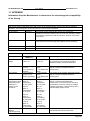
1
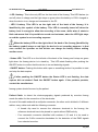
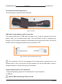
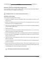
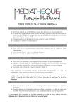
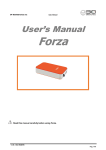
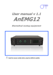
OT Bioelettronica snc User Manual Spes Medica S.r.l User’s Manual foremg Read this manual carefully before using foremg. 0476 This product is manufactured in compliance with the CE European Medical Device Directive and later directives and additions (2007/47 directive) and according to the reference norms CEI EN 60601-1, 60601-1-2, 60601-1-11, 60601-2- 40, 60601-1-6, CEI IEC 62304, Directive 2002/96/CEE v1.3 – Ed. 06/2013 Pag. 1/22 OT Bioelettronica snc User Manual Spes Medica S.r.l Spes Medica s.r.l. Via Europa Zona Industriale 84091 Battipaglia (Sa) tel. +39 0828 614191 fax +39 0828 331788 www.spesmedica.com [email protected] v1.3 – Ed. 06/2013 Pag. 2/22 User Manual OT Bioelettronica snc Spes Medica S.r.l SYMBOLS USED The graphic symbols used on this device and on this manual refer to the UNI EN ISO 980 Law, CEI EN 60601-1, RAEE Law and 2002/96/ECC Directive. SYMBOL DESCRIPTION Serial Number Device with BF parts. Class II device Warning, read the instructions before using the device. This symbol could also be used as a “Warning” symbol Read the instructions of use Manufacturer Do not dispose this product as unsorted municipal waste. Collection of such waste separately for special treatment is necessary following the 2002/96/EC Law of the European Parliament and Council of the European Union about the disposal of e-waste. The foremg device has been tested in reference to the EN 60601-1 and the EN 60601-1-2 Law. If the user connects the foremg device to any other unauthorized device following the EN 606011 and EN 60601-1-2 Laws, he/she has to ensure that the combined use of the two devices follows the laws above mentioned. Otherwise Spes Medica S.r.l shall not be held liable for accidents and/or injuries to persons or damage. For the features of the software, read the Software Manual. v1.3 – Ed. 06/2013 Pag. 3/22 OT Bioelettronica snc User Manual Spes Medica S.r.l 1. INDEX 1 GENERAL DESCRIPTION .......................................................................pag. 5 2.INTENDED USE ....................................................................pag. 5 3. PLACE OF USE ......................................................................................pag. 5 4. USER PROFILE .....................................................................................pag. 6 5. SAFETY PRECAUTIONS AND WARNINGS ..........................................pag. 6 6. CONTENT OF THE FOREMG SYSTEM ..................................................pag. 7 7. DETAILED DESCRIPTION .....................................................................pag. 8 Patient Cable ..................................................................................pag. 10 Chest belt .......................................................................................pag. 10 USB cable for battery charge process and PC connection .............pag. 10 System requirements for PC connection.........................................pag. 11 Behaviour of the device during battery charge process ..................pag. 11 Application of the foremg device .....................................................pag. 11 Memory file ....................................................................................pag. 12 8. TROUBLE SHOOTING ...........................................................................pag. 13 9.MAINTENANCE AND STORAGE .............................................................pag. 14 Cleaning the device ........................................................................pag. 14 Disposal of the device .....................................................................pag. 14 Life span of the device ....................................................................pag. 15 10. TECHNICAL SPECIFICATIONS ............................................................pag. 16 11. APPENDIX …… .....................................................................................pag. 17 Information about the Electromagnetic compatibility .......................pag. 17 CUSTOMER SERVICE …… ........................................................................pag. 19 WARRANTY …….......................................................................................pag. 19 foremg warranty activation form .....................................................pag. 21 v1.3 – Ed. 06/2013 Pag. 4/22 OT Bioelettronica snc User Manual Spes Medica S.r.l 1. GENERAL DESCRIPTION The foremg device is a four-channel Holter. This system has been designed to detect the surface electromyography signal (sEMG) from four muscles trough the use of the concentric electrodes called CoDe or using standard bipolar electrodes. The information detected from the electrodes is then saved on a non-removable Micro SD card inside the device. The foremg works with a software called OT BioLab in order to display and process the data. This software is part of the foremg system and it is also possible to download it free on the website www.otbioelettronica.it in the Downloads section. 2. INTENDED USE foremg has been designed to be used as an electromyography Holter to monitor muscles activity. The device is not intended to be used near inflammable anaesthetics. The device is not intended to be used for an electrocardiographic exam. 3. PLACE OF USE foremg is intended to be used as a home device and a hospital device: as a home device, the patient uses the device at home during the day and as a hospital device the operator uses the information detected from it in order to make a diagnosis. v1.3 – Ed. 06/2013 Pag. 5/22 OT Bioelettronica snc User Manual Spes Medica S.r.l 4. USER PROFILE USER: Patient a) Age : >15 years-old b) Weight: not important c) Health: no heart problems or pacemakers d) Nationality: not important e)Patient status: able to understand the use of foremg. Education level: High school Knowledge: Minimum.Basic notions about the human body Languages: Italian and/or English Experience: Minimum . Minimum training about the device use Handicaps: - maximum reduction of the hearing of 40% with residual hearing at 60%; - maximum sight reduction of 40% with residual sight at 60% 5. SAFETY CAUTIONS AND WARNINGS The use of foremg is forbidden in the following conditions: Simultaneous use of electro surgery systems, shortwave or microwave therapy or near these type of devices; Unsound mind patient; The device is damaged; Near inflammable anaesthetics with air, oxygen or nitrous oxide. To make an electrocardiographic exam Pacemaker users These warnings must be followed: Contact immediately the manufacturer if foreign materials (liquids, etc.) come into contact with the device. If the device falls in to the ground or something similar happens, check that the device is undamaged. In case of doubt, contact the manufacturer. v1.3 – Ed. 06/2013 Pag. 6/22 OT Bioelettronica snc User Manual Spes Medica S.r.l The foremg could be sensitive to electromagnetic interferences of other devices that could alter its electromyography measurements and consequently the physiological variables calculated on the basis of the information detected. For this reason, do not use it near devices that could cause the problems described above, for example mobile phones, instruments with power transformer, etc. The operator must be sure that the battery of the device is completely charged following what is indicated in this User’s Manual before to give the device to the patient. The device must be kept out of reach of children or unsound mind patient Do not clean the device using acetone, ether, freon, oil products or any other solvent Do not use soap or water on the connector pin Do not clean foremg or connection cables with water, in autoclave or steam cleaning The device must not be used in any other way than indicated in these instructions 6. CONTENT OF THE FOREMG KIT ACCESSORIES AND DOCUMENTS Description USB connection cable: battery charge and PC connection Connection cable for the recording electrodes CUSB01 CPAT01 BRUXBELT000 Chest belt with device Features NONSTERILE NON STERILE NON STERILE REUSABLE RIUSABILE RIUSABILE The accessories of the machine indicated above are to be considered as part of the device itself, so they are not subject to marking. ACCESSORIES NEEDED BUT NOT INCLUDED IN THE STANDARD EQUIPMENT Description CDE02401500BX Bipolar Electrodes Use of the equipment accessories and/or STERILE NO SINGLE-USE YES accessories of the Spes Medica s.r.l to be used for the detection of the electromyography signals. v1.3 – Ed. 06/2013 Pag. 7/22 User Manual OT Bioelettronica snc Spes Medica S.r.l 7. DETAILED DESCRIPTION Controls, indicators and connectors of the foremg are shown in Fig. 1 and described in the following sections. Connector alimentazione/elettrodi LED 2 ON/OFF Button batteria Frontal View Status Led ON/OFF 0476 SN: FXXXX-MMAAAA foremg IP 32 Spes Medica Srl 16129 – Genova - Italy Designed and Developed by OT Bioelettronica 10135 - Torino - Italy otbioelettronica.it Posterior View Connector alimentazione/elettrodi LED 1 battery Fig. 1: Front view and Back view of the foremg Description of controls, indicators and connectors shown in fig.1: - Power/ Electrodes Connector: It is the connector to which the adapter should be connected for the detection of the signals and charge battery/download data connector. To switch on the device the patient cable connector must be connected to the device v1.3 – Ed. 06/2013 Pag. 8/22 OT Bioelettronica snc User Manual Spes Medica S.r.l - LED 1 battery: This is the only LED on the front side of the foremg. This LED flashes (on and off) when in charge and the light stays on green when the battery is 100% charged or when the device is on charge and connected to the PC - LED 2 battery: This LED is on the right side of the back of the foremg. It is identified by the symbol of the battery. This LED is normally turned off when the battery level is enough to allow the recording of the exam, while when it starts to flash red means that it is possible to record one last exam, when the LED light stays on red the system is not recording anymore. When the battery LED on the right side of the back of the foremg (identified by the battery symbol) stays on red light, the device is not recording anymore. In that case contact the operator so that he/she can charge the battery before making another exam. - Status LED: This LED is on the left side of the back of the foremg and it stays on green light when the foremg device is in stand-by. This LED starts flashing after pushing the ON/OFF button to confirm that the device is on and detecting signals. - ON/OFF button: Pushing this button with a pen or something similar it is possible to start and stop the data capture. If after pushing the ON/OFF button the Status LED is not flashing, the data capture did not started. Push the ON/OFF button again. If the problem persists, contact the manufacturer. foremg system should be worn by the patient. Patient Cable: to detect the electromyography signals produced by muscles foremg needs the cable for the connection of the electrodes. An end of this cable ends with a multipolar connector; the other end is divided in 5 different cables: every cable ends with the following connector: - A female clip used to connect the reference electrode to the foremg, the reference electrode has to be placed in a point without EMG activity - Four concentric connector identified with numbers 1,2,3 and 4 to be used to connect the CoDe concentric electrodes for the detection of the EMG signals from selected muscles. v1.3 – Ed. 06/2013 Pag. 9/22 OT Bioelettronica snc User Manual Spes Medica S.r.l The chest belt of the foremg device The foremg device uses the bruxoff chest belt. Fig. 2: Chest Belt USB cable: charge battery and PC connection The foremg device has an USB cable as shown in fig. 3 and the operator (but not the patient) uses it as a double-function cable. The first function is that of connecting the foremg to a PC so that the software can download and then process the data. The second function is that of charging the battery once connected to a PC. Fig. 3: Cable for data downloading/ battery charge The connection to the PC and charging of the foremg device is allowed only in the operator office or clinic, not at home. Only the operator can use the USB cable in order to charge the battery: it should not be given to the patient. System Requirements for PC connection 1. Windows Operating system for PC (Windows XP, Vista, Windows 7) 2. USB port Use the USB cable that you find in the kit. v1.3 – Ed. 06/2013 Pag. 10/22 OT Bioelettronica snc User Manual Spes Medica S.r.l Behaviour of the device during battery charge process During the battery charge process the green LED on the front side of the foremg flashes. When the device is fully charged the LED stays on. Charge the device for at least 4 hours before to use it. Application of the foremg How to apply the foremg system correctly: connect the multipolar connector of the patient cable to the multipolar connector on the foremg device; take the electrodes and remove the protective liner, then apply them, that is to say in direct contact with the investigated muscles; Take the clip of the reference cable and connect it to the reference electrode displaced on a point without EMG activity. Wear the chest belt; Connect the four concentric connectors numbered with the number 1, 2, 3 and 4 to the respective concentric connectors of electrodes; Push the ON/OFF button with a pen or something similar to start the recording. Be sure that the status LED is flashing green. If the LED does not flash, go to section 10 of this manual “troubleshooting”. Insert the foremg in the appropriate pocket of the chest belt and get ready to go to make the acquisition; To stop the acquisition, push the ON/OFF button again with a pen or something similar to stop the recording; Remove the electrodes and disconnect them. Disconnect the patient cable from the foremg, and then put the device and its accessories (chest belt and patient cable) back in its packaging. Throw away the single-use electrodes. . The single-use bipolar electrodes cannot be reused. v1.3 – Ed. 06/2013 Pag. 11/22 OT Bioelettronica snc User Manual Spes Medica S.r.l Memory file Files are saved on the Micro SD Card with a standard name. The name structure is: EMG4CH_n.BIO Where n is the number of recordings increasing every time the button ON/OFF is pushed. It can assume values in numbers and values in letters as well: 0, 1, 2... 8, 9, A, B... Z. so that in the system can coexist up to 36 different files. If all the 36 available recordings have been made, foremg does not allow the uploading of new files. The user should copy and delete the files on the Micro Sd Card in order to have new file names to be used again. Every time the device is turned off, that is to say disconnected from the connector, the numbering of the files restart from “EMG4CH_0.BIO”. The foremg does not have a clock, so the date and the time of the file do not display the moment in which they are saved. Time and date start from 00.00 of the 1st January 2012 and increase of 1 hour with every new recording. The foremg0.bio file will be saved with the date 1/1/2012 and time 00:00, the foremg1.bio will be saved with the date 1/1/2012 and time 01:00 etc... Order the recording files chronologically in order to have a temporal order of creation of them. v1.3 – Ed. 06/2013 Pag. 12/22 OT Bioelettronica snc User Manual Spes Medica S.r.l 8. TROUBLESHOOTING This section describes the most common problems that may be found by foremg users. Problem Description How to deal with it After pushing the ON/OFF button the Memory not available: if the problem persists, LED 2 (red) stays on. contact the manufacturer. The LED 2 (red) stays on Low Battery. Charge the battery before using the device. The LED 2 (red) flashes Battery almost low but charged enough to record one last exam. The status LED (green) does not The recording did not started. Push the ON/OFF flashes. button again. If the problem persists, contact the manufacturer. No file saved at the end of the The recording did not started: check that after recording. pushing the ON/OFF button the (green) status LED starts to flash. v1.3 – Ed. 06/2013 Pag. 13/22 OT Bioelettronica snc User Manual Spes Medica S.r.l 9. FOREMG MAINTENANCE AND STORAGE foremg has to be used, transported and stored in the following conditions: Temperature: from 10°C to +40°C Maximum relative humidity: from 30% to 75% Atmospheric pressure: from 700 hPa to 1060 hPa It is recommended to turn off the foremg at the end of every session. foremg should be stored with all the enclosed accessories on a safe place far from all the conditions described in the section Warnings of this manual. foremg does not need any particular maintenance procedure to work. To maintain the battery efficiency, recharge the device before every use and check regularly the efficiency status of the battery. If during the use and after the battery charging the battery lasts less than 3 hours, contact the manufacturer to check the controls of the electrical source itself. Cleaning the device: At the end of every use clean the foremg with a clean cloth. Do not clean foremg using acetone, ether, freon, oil products or any other solvent; Do not use soap or water on the connectors pin contacts. Do not clean foremg or its cables with water, in autoclave or with steam cleaning. WARNING: clean the electrodes connection cable only with hospital disinfectants before every use to avoid microbial contamination between patients and healthcare professionals. Product Disposal The foremg contains electronic parts that must be disposed of as e-waste. Dispose the device and the accessories following local regulations. Follow the disposal regulations of your country in order to ensure the correct disposal of the foremg and its accessories. For v1.3 – Ed. 06/2013 Pag. 14/22 OT Bioelettronica snc User Manual Spes Medica S.r.l further information about the disposal of this device, contact the Environment Department and local authority. Warning: Do not dispose this product as unsorted municipal waste. Collection of such waste separately for special treatment of necessary, following the 2002/96/EC of the European Parliament and European Council on waste electrical and electronic equipment. (WEEE). The regulation is not valid in case of corrupted product. Life span of the device The foremg system is produced in order to last, if the use and maintenance conditions indicated in this User’s manual are followed, but the life span of the device is determined by the life span of the battery (5 years). After this period it is recommended to take the device to the manufacturer every two years. v1.3 – Ed. 06/2013 Pag. 15/22 User Manual OT Bioelettronica snc Spes Medica S.r.l 10. TECHNICAL SPECIFICATIONS The foremg device is a battery system designed following the medical regulations in order to ensure the patient safety. The signal amplified by the system is saved as a proprietary file on a non-removable MicrdoSdcard inside the system. In table 1 there are the technical specifications of the foremg. Model foremg Classification Battery system Degree of Protection IP32 Case Metallic case Power Supply 3,7V Battery, rechargeable Battery time 36 Hours (full charge) Charging time 5 hours Class II Numbers of Channels 4 Dynamics 972 VPP Band 13 ÷ 400Hz Input Noise < 2 VRMS Amplification 3.393 V/V (+/- 2%) Input impedance > 90 M on the entire bandwith CMRR >96 dB Output Dynamics 0 ÷ 3.3 V A/D converter resolution 8 bits Data memory Micro SD inside the device Sampling rate 800 Hz Commands 1 button Dimensions 59 x 95 x 10 mm Weight 110g TAB. 1: Technical Specifications of the foremg v1.3 – Ed. 06/2013 Pag. 16/22 User Manual OT Bioelettronica snc Spes Medica S.r.l 11. APPENDIX Information from the Manufacturer in reference to the electromagnetic compatibility of the foremg EMISSIONS The foremg device is designed and made to work in an electromagnetic environment with the following conditions. The foremg user must ensure that it is used in these conditions Test of emissions Conformity Electromagnetic Environment-guide RF Emissions Gruppo 1 The foremg product uses the RF energy only for its inner functioning, so its RF emissions are very low and most likely it does not cause any interference with the electronic devices in the same environment. RF Emissions B Class Harmonic Emissions Flicker Emissions A Class Adequate Table 202 Immunity Test Electrostatic charge Transients Overvoltages Voltage interruptions, short interruptions and variations of voltage on the input lines Mag at the network frequency(50 Hz) The foremg product can be used in every environment, at home and where there is an electrical grid that supplies houses/ buildings IMMUNITY Test level 60601-1-2 ± 6 kV contact ± 8 kv air Conformity level Electromagnetic environment-guide ± 6 kV contact ± 8 kv air Pavements must be of wood, piling, ceramic. If pavements are of synthetic material, relative humidity must be at least 30% The quality of the voltage network should be that of a common hospital/ business environment. < 5% Ut (95% of interruption) for 0,5 cycles ± 2 kV common mode ± 1 kv differential mode ± 2 kV common mode ± 1 kv differential mode < 5% Ut (95% of interruption) for 0,5 cycles 40% Ut (60% of interruption) for 5 cycle 40% Ut (60% of interruption) for 5 cycles 70% Ut (30% of interruption) for 25 cycles 70% Ut (30% of interruption) for 25 cycles < 5% Ut (95% of interruption) for 5 seconds 3 A/m < 5% Ut (95% of interruption) for 5 seconds 3 A/m ± 2 kV phase(i)ground ± 1 kv phase (i)phase(i) ± 2 kV phase(i)ground ± 1 kv phase (i)-phase(i) The quality of the voltage network should be that of a common hospital /business environment. The quality of the voltage network should be that of a common home/business environment. If the foremg user calls for a continuative work even during the voltage network interruption, charge foremg with a uninterruptible power source The frequency magnetic field must have home/business environment levels. v1.3 – Ed. 06/2013 Pag. 17/22 User Manual OT Bioelettronica snc Table 202 Immunity Test Spes Medica S.r.l IMMUNITY Test Level 60601-1-2 Conformity Levels Electromagnetic environment-guide d 1,17 P Conducted Radio Frequency 3 Veff 3 Veff Where P is the maximum output power of the transmitter in W by the manufacturer of the transmitter and d is the distance of separation in metres d 0,35 P from 80 MHz to 800 MHz d 0,7 P from 800 MHz to 1 GHz Irradiated Radio Frequency 10 V/m (26 MHz÷1 GHz) 3 V/m (1GHz÷2,5GHz) d 2,33 P from 1 GHz to 2,5 GHz 10 V/m 3 V/m Where P is the maximum output power of the transmitter in W by the manufacturer of the transmitter and d is the distance of separation in metres DISTANCE OF SEPARATION RECOMMENDED BETWEEN PORTABLE AND MOVABLE COMUNICATION DEVICES AND THE FOREMG DEVICE foremg is made to work on an electromagnetic environment where the radiofrequency distortions are under control. The foremg user or operator can avoid electromagnetic interferences ensuring a minimum distance between the RF (transmitters) movable and portable communication devices and, as described below, in relation to the maximum output power of the radio communication devices. Distance of separation to the transmitter frequency (m) Maximum Output power of the transmitter (W) From 15 kHz to 80MHz 0,01 0,12 0,1 0,37 1 1,17 10 3,69 100 11,67 From 80MHz to 800MHz 0,04 0,11 0,35 1,11 3,50 From 800MHz to 1GHz 0,07 0,22 0,70 2,21 7,00 From 1GHz to 2,5GHz 0,23 0,74 2,33 7,38 23,33 v1.3 – Ed. 06/2013 Pag. 18/22 OT Bioelettronica snc User Manual Spes Medica S.r.l CUSTOMER SERVICE foremg has no parts that can be replaced or repaired by the user; contact the distributor for assistance so that he/she can repair or replace the products under warranty. Maintenance and replacement of parts, modifications and/or reparations made by unauthorized Companies and/or operators by Spes Medica S.r.l will forfeit entitlement to warranty. Spes Medica S.r.l. denies any and all responsibility for damages caused directly or indirectly as a result of maintenance, replacement of parts, modifications and/or reparations made by Companies and/or operator that are not authorized by the Spes Medica S.r.l. foremg does not need any prior maintenance. WARRANTY Spes Medica S.r.l ensures that every new product has no defects due to materials and labour and will repair and/or replace in warranty products used following the intended use and used in the use conditions described in this manual. Warranty lasts 2 years only after filling and signature of the warranty application form that you find below. Warranty conditions: the obligations of Spes Medica S.r.l following the warranty are limited exclusively to what follows: - reparation will be made by and no later than 30 work days after the receipt of the product and only after the verification that the malfunctioning is not due to inadequate or inaccurate use, maintenance and /or reparation. v1.3 – Ed. 06/2013 Pag. 19/22 OT Bioelettronica snc User Manual Spes Medica S.r.l If Spes Medica S.r.l verifies that the malfunctioning is not due to inadequate or inaccurate use or unauthorized maintenance/reparation, the reparation costs (materials and labour) will be invoiced only after acceptation of the budget of reparation by the owner These warranty conditions substitute all the other warranty conditions, explicit or implicit, included, but not within limits of the general conditions specified in the international sale regulations. Spes Medica S.r.l reserves the right to refuse the reparation of any products sent by the user for reparation; this refusal will be conveniently explained. The only obligation of Spes Medica S.r.l. is that of returning the product to the user at its own expenses. v1.3 – Ed. 06/2013 Pag. 20/22 User Manual OT Bioelettronica snc Spes Medica S.r.l foremg WARRANTY ACTIVATION FORM : a copy of this module filled and signed by the Costumer must be sent back by e-mail, fax or mail to: Spes Medica S.r.l. – Via Europa –Zona Industriale – 84091 Battipaglia (SA) – Italy Tel: +39 (0)828 614191 – fax: +39 (0)828 341788 e-mail: [email protected] TO BE FILLED BY THE CUSTOMER foremg Serial Number foremg Date of Sale Purchase Address City Country ZIP CODE Tel.: fax: e-mail: To be covered by warranty, you must certify that: Your foremg will be used only according with User’s Manual All unexpected occurrences and malfunction associated with the foremg will promptly be reported to Spes Medica S.r.l. – Via Europa –Zona Industriale – 84091 Battipaglia (SA) – Italy I declare to have understood and accepted the Warranty terms Stamp and Signature Date Spes Medica S.r.l. warrants the foremg to be free from defects in material or factory workmanship in the course of normal use and service. The manufacturer's obligation under this warranty is limited to repairing or replacing any defective part, provided that the unit is returned, unmodified, to Spes Medica S.r.l, and that the defect has occurred within one year of the original date of purchase. A handling/postage charge will be at charge of the Customer. This warranty is void if the purchaser has not returned a copy of this document, signed by the responsible party of the purchaser, and completely executed. Spes Medica S.r.l. expressly disavows any medical liability for the improper use of this device. This warranty does not apply (is void) to any unit which has been repaired in any way or modified by unauthorized personnel, or which has been subject to misuse, neglect or accident; or which has had the serial number altered or removed Notes v1.3 – Ed. 06/2013 Pag. 21/22 OT Bioelettronica snc User Manual Spes Medica S.r.l Manufactured by: Spes Medica srl Via Europa (Zona Industriale) 84091 - Battipaglia (Sa) - ITALY www.spesmedica.com e-mail: [email protected] Designed in collaboration with and Distributed by: OT Bioelettronica C.so Unione Sovietica 312 10135 – Torino (TO) - ITALY www.otbioelettronica.it e-mail: [email protected] v1.3 – Ed. 06/2013 Pag. 22/22