1
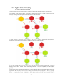
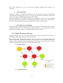
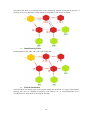
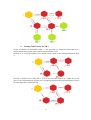
ZigBee Router EX-9212-Z Operation Manual First Edition, May 2011 0 Disclaimer Information in this document is subject to change without notice and does not represent a commitment of ours. We reserve the right to make improvements and/or changes to this manual, or to the products and/or the programs described in this manual, at any time. We assume no responsibility for its use, or for any infringements on the rights of third parties that may result from its use. This product might include unintentional technical or typographical errors. Changes are periodically made to the information herein to correct such errors, and these changes are incorporated into new editions of the publication. Reproduction of the contents of this copyrighted publication, in whole or part, without written permission of ours, is prohibited. Throughout this manual we use notes to make you aware of safety consideration. Important User Information Because of the variety of uses for the products described in this publication, those responsible for the application and use of this control equipment must satisfy themselves that all necessary steps have been taken to assure that each application and use meets all performance and safety requirements, including any applicable laws, regulations, codes and standards. The illustrations, charts, sample programs and layout examples shown in this guide are intended solely for purposes of example. Since there are many variables and requirements associated with any particular installation, we do not assume responsibility or liability (to include intellectual property liability) for actual use based upon the examples shown in this publication. Caution Risk of injury or equipment damage exists. Only personnel familiar with drive and power products and the associated equipments should plan or implement the installation, star-up, configuration, and subsequent maintenance of the product using a serial converter. Failure to comply may result in injury and/or equipment damage. 1 Preface Related documents Item: 1 2 3 4 5 Refer to: User Manual Quick Installation Guide Specification Sheet Firmware Update Manual CE/FCC Approval Letter Publication: Notice: Supporting documentation can be obtained from your local dealer or distributor. It can also be viewed on website. Related Software and Firmware Item: 1 2 Refer to: Device Management Utility Firmware Notice: Any version change or upgrade without notifies. 2 Version: Table of Contents Chapter 1 Introduction 1.1 Overview ………………………………………………………..… 4 1.2 Package Checklist ………………………………………………… 5 1.3 Block Diagram …………………………………….……………… 5 1.3.1 CPU Diagram ……………………………………………….. 5 1.3.2 General Features ………………………………………….… 6 1.4 Product Features …………………………………...…………….. 7 1.4.1 ZigBee Network Nodes ……………………………………… 7 1.4.2 ZigBee Network Topology …………………….…………….. 7 1.4.3 Ideal Applications for ZigBee ……………………..………… 8 1.5 Product Specifications ……………………….……………………. 9 1.6 Dimension …………………………….…………………………… 10 Chapter 2 Hardware Introduction 2.1 Product Panel Overview ………………………………………….. 11 2.2 Port Description …………..………………………………………. 11 2.2.1 Antenna Jack……………………………………………………. 11 2.2.2 Power DC Jack ……………………………………………... 11 2.2.3 Pair / Set Button ………….………………………………… 12 2.3 LED Indicator ……………………………………….……………. 12 Chapter 3 Getting Start 3.1 Hardware Installation ………………………….………………… 13 3.1.1 DIN-Rail Mounting ………………………….…………...... 13 3.1.2 Wall Mounting …………………………………….…..…… 14 3.2 ZigBee Technical Foundations …………………………………… 15 3.2.1 ZigBee Device Types …………………………..…………… 15 3.2.2 ZigBee Mesh Networking …………….……………………. 17 3.2.3 ZigBee Broadcast Messages …..…………………………… 18 3.2.4 ZigBee Network Architecture …..…………….…………… 23 3.3 The Device’s Pairing Procedure ………….……….……………… 24 . 3 Chapter1. Introduction The ZigBee protocol was developed to provide low-power, wireless connectivity for a wide range of network applications concerned with monitoring and control. ZigBee is a worldwide open standard controlled by the ZigBee Alliance. The ZigBee standard builds on the established IEEE 802.15.4 standard for packet-based wireless transport. ZigBee enhances the functionality of IEEE 802.15.4 by providing flexible, extendable network topologies with integrated set-up and routing intelligence to facilitate easy installation and high resilience to failure. ZigBee wireless connectivity means that it can be installed easily and cheaply, and its built-in intelligence and flexibility allow networks to be easily adapted to changing needs by adding, removing or moving network nodes. The protocol is designed such that nodes can appear in and disappear from the network, allowing some devices to be put into a power-saving mode when not active. 1.1 Overview We provide new ways of wireless connecting devices as ZigBee and we provide entire series of ZigBee products as ZigBee to Ethernet port, ZigBee to serial port (RS-232/422/485) with D I/O of EX-9000/ EX9000-M series and, ZigBee Router over ZigBee wireless network. The “ZigBee Router” device is usually played a role of router and bridge at the ZigBee network. The data can transmit via ZigBee 801.15.4 protocol. ZigBee Router is designed for extending the transmission distance between “ZigBee Coordinator” and “ZigBee End Device” and data routing over ZigBee wireless network. The device is packaged in a PVC case well suited for industrial environments. The ZigBee wireless converter is a low-cost, high performance design. By careful selecting high quality with competitive prices components in the world, the products made network connectivity possible with affordable cost for virtually all kinds of devices. This ZigBee wireless converter Series consists of three models EX-9212-S, EX-9212-E, EX-9212-Z: EX-9212-Z is a bridge router device of wireless ZigBee which it is a multi-access device with routing function. EX-9212-S is a serial to ZigBee converter device within one serial port of RS-232/422/485 (Auto-Detection). EX-9212-E is a TCP/IP Ethernet port to ZigBee converter device within one Ethernet 10/100Mbps of RJ-45 port. This user manual will guide you step by step for the various functions of this converter. 4 1.2 Package Checklist Converter is shipped with the following items: ZigBee Device x 1 User Manual CD x USB-female cable with B type and A type connectors x 1 Notice: Notify your sales representative if any of the above items is missing or damaged. 1.3 Block Diagram 1.3.1 CPU Diagram ZigBee module provides a cost-effective RF transceiver solution for 2.4GHz IEEE 802.15.4 data links and ZigBee wireless networks and is based on the Ember™ EM250 platform. The single-chip solution consists of an IEEE 802.15.4-compliant 2.4GHz RF transceiver with a 16-bit XAP2b microprocessor. It’s designed to support point to point, point to multi-point, and mesh network applications. The EM250 from Ember provides a ZigBee System-on-Chip that combines a 2.4GHz IEEE 802.15.4 compliant radio transceiver with a 16-bit microprocessor. The radio provides best-in-class RF performance with excellent sensitivity and transmits power for long range, and 802.11immunity. A flexible RF interface minimizes external components in configurations with or without external LNA/PAs. Designed specifically for use with EmberZNet, Ember’s ZigBee 5 compliant embedded mesh networking software, the EM250 is optimized for designs requiring long battery life, low external component count, and a reliable, proven, industry-standard networking solution. Innovative on-chip debugging (Insight Port) provides developers with the most advanced views into their application and network available in the industry. 1.3.2 General Features - Ember™ EM250 platform - 128KB Flash memory - 5KB SRAM - 16-bit XAP2b microprocessor - 17 general purpose I/O ports - DMA-SPI, I2C and UART interfaces - Integrated 12-bit resolution ADC - Designed for EmberZNet ZigBee Pro compliant networks - Miniature footprint: 2cm x 3cm - Integrated PCB trace antenna and U.FL external antenna connector - 16 RF channels - Over indoor 30m and outdoor visual contact 100m of range - Non-intrusive debug interface (SIF) - AES 128-bit encryption - Low power consumption - Constant RF out power over 2.1~3.6 V voltage range - FCC and NCC certification in process - RoHS compliant 6 1.4 Product Feature 1.4.1 ZigBee Network Nodes A wireless network comprises a set of nodes that can communicate with each other by means of radio transmissions, according to a set of routing rules (for passing messages between nodes). A ZigBee wireless network includes three types of node: ● Coordinator Node: This is the first node to be started and is responsible for forming the network by allowing other nodes to join the network through it. Once the network is established, the Co-coordinator has a routing role (is able to relay messages from one node to another) and is also able to send/receive data. Every network must have one and only one Coordinator (as EX-9212-S, EX-9212-E). ● Router Node: This is a node with a routing capability, and is also able to send/receive data. It also allows other nodes to join the network through it, so plays a role in extending the network. A network may have many Routers. There is only the EX-9212-Z to play a route node of ZigBee networks in EX-9212 series. ● End Device Node: EX-9212-S are usually played the role of the end-device for collecting data from the serial device. This is a node which is only capable of sending and receiving data (It has no routing capability). A network may have many End Devices. 1.4.2 ZigBee Network Topology ZigBee facilitates a range of network topologies from the simplest Star topology, through the highly structured Tree topology to the flexible Mesh topology. ZigBee is designed primarily for Mesh networks. A Mesh network has little implicit structure. It is a collection of nodes comprising a “Coordinator Device” and a number of “Router Devices” and/or “End Devices”. - Each node, except the “Coordinator Device”, is associated with a “Router Device” or the “End Device” - this is the node through which it joined the network and is known as its ‘parent’. Each parent may have a number of ‘children’. - “End Device” can only communicate directly with its own parent. - Each “Router Devices”, “End Devices” and the “Coordinator Device” can communicate directly within radio range. The “Coordinator Device plays as a role of routing table manager for monitoring and managing the routing status of the ZigBee network. It is the last property above that gives a mesh network its flexibility and efficiency in terms of inter-node communication. A mesh network is illustrated in the figure below. 7 1.4.3 Ideal Applications for ZigBee ZigBee is suitable for a wide range of applications, covering both commercial and domestic use, which it includes: - Point-to-point cable replacement (e.g. wireless mouse, remote controls, toys) - Security systems (e.g. fire and intruder) - Environmental control (e.g. heating and air-conditioning) - Hospital patient monitoring - Lighting control - Home automation (e.g. home entertainment, doors, gates, curtains and blinds) - Automated meter reading (AMR) - Industrial automation (e.g. plant monitoring and control) ZigBee wireless communications also enable some applications to be developed that currently cannot be implemented with cabled systems. Examples are applications that involve mobility, which must be free of cabling (e.g. long-term health monitoring, asset tracking in warehouses). Existing applications (such as lighting control and industrial plant monitoring) that currently rely on cable-based systems can be implemented more cheaply as ZigBee reduces or removes cable installation costs. ZigBee can also be beneficial in environments where cable-based solutions can be difficult and expensive to install - for example, in home security systems, sensors need to be easy to install. 8 1.5 Product Specifications Hardware Power CPU:Ember™ EM250 16-bits CPU, 24 MHz RAM:5K Bytes SRAM ROM:128K Bytes Flash ROM DC 9 ~ 24 V / 150 mA@9V, 60 mA @ 24V Over Current & Reverse Protection ZigBee IEEE 802.15.4 compliant Frequency: ISM band 2400 ~ 2480MHz Receiver Sensitivity: -95dBm RF Output Power: 3 dBm RF Output Power:18 dBm, (EX-9212-Z-h for High Power) Sleep Current: 1uA (with active sleep timer) TX current < 24 mA , RX current < 28 mA Security processor (128 bits AES) Operation Voltage: 2.1 V~ 3.6V Antenna: SMA Type, 2 dBi, changeable Distance: Up To 150~200 Meters in free space (600~800 Meters for High Power) Data Rate: 250K bps Application Mode: Mesh LED Indicators SYS (red), Pairing (green), Rx (red), TX (green) Environment Operating Temperature:0 ℃ ~ +75℃ Storage Temperature:-20℃ ~ +85℃ Dimensions 100 x 90 x 25 mm (W x D x H) Weight 150 gm. (Not include power adapter) Wall Mountable Din-Rail (Optional) Regulatory Approvals RoHS Warranty 1 year Setup Tool Windows Utility 9 1.6 Dimension 10 Chapter2. Hardware Introduction 2.1 Product Panel Overview 2.2 Port Description 2.2.1 Antenna Jack The connector of antenna is a standard reverse SMA jack. Simply connect it to a 2.0dBi (Standard) or 5.0dBi dipole antenna (Standard Rubber Duck) and it is 50 Ohms impedance and can support 2.4GHz frequency 2.2.2 Power DC Jack The ZigBee device has two DC power input for choice. One is powered by a single 9Vdc (inner positive/outer negative) power adapter and 500mA of current. A suitable power supply adapter is part of the packaging. DC-In power outlet is at the left side of ZigBee device and put the adapter into the socket. Other one is usually supplied DC +24 V in the computer center directly and you may use “DC power terminal block” for inputting the power. If the power is properly supplied, the “PWR” red color LED will be on. 11 2.2.3 Pair / Set Button The “Pair/Set” button is for pairing the devices and use a pin to push the Pair/Set button for active it. For more detail information please see chapter 3.3 “The device’s pairing procedures”. 2.3 LED Indicators The LEDs indicate of the device status. PWR Indicator: It is a power indicator (When the power is on, the LED will be on.) Pair Indicator: It shows the device indicator of pairing status and when ZigBee End Device is operated in pair status then the LED will be blink every three seconds. The pair LED indicator of ZigBee Coordinator is normally blinking once per 3 seconds and when active the pairing function within 60 seconds period that the pair LED indicator will be blinked once second. Rx Indicator: Data received indicator (When packet are receiving from the network, the LED will blink.) Tx Indicator: Data sent indicator (When packets are sending to the network, the LED will blink.) 12 Chapter3. Getting Start Before Getting Started Administrators should read this part of the manual carefully, especially during installation. Please verify that all the items in the Package Checklist are presented. Before initial installation and configuration the device, you will also need a PC or notebook PC within Ethernet port. Step 1: Connect the power source Please find a suitable AC-DC power adapter which it is a part of the packaging. The converter device is powered by a single 9VDC (inner positive/outer negative) power source with 500mA of current. The adapter of AC input power is autosensing design from 110∼240 voltage. The DC power jack at the left side of the ZigBee device and put the adapter into the socket. If the power is properly supplied, the “PWR” LED will be on. Step 2: Check the power status of the device When power is connected and users can verify the LED indicator of “PWR” on the top panel. If the power is properly supplied, the “PWR” LED indicator will be on that if the power input fails, LED indicators will not be light up. Step 3: Check the status of the device after connecting the power When power is properly worked and the next step is to pairing with “ZigBee Coordinator” device. To verify the LED indicator of “Pair”, if the pair is successful that the “Pair” LED indicator will be blinking every three seconds. 3.1 Hardware Installation 3.1.1 DIN-Rail Mounting The aluminum DIN-Rail attachment plate is included in the package. If you need to reattach the DIN-Rail attachment plate to the converter, make sure the stiff metal spring is situated towards the top, as shown in the figures below. The DIN-Rail attachment plate should already be attached to the back panel of the converter device. If you need to reattach the plate, make sure the metal spring is situated towards the top, as shown in the figures below. STEP 1: Insert the top of the DIN-Rail into the slot just below the metal spring. 13 STEP 2: The unit will snap into place as shown below. 3.1.2 Wall Mounting Step 1: There are two brackets on both sites of the converter device and it come standard with the converter. They are used to attach the converter to a wall, or the inside of a cabinet. Use two screws per bracket to attach the converter to a wall (Figure 3.8). Step 2: The heads of the screws should be less than 6.0 mm in diameter, and the shafts should be less than 3.5 mm in diameter, as shown in the figure 3.8 at the up .Do not screw the screws in all the way—leave a space of about 2 mm to allow room for sliding the wall mount panel between the wall and the screw heads. 14 3.2 ZigBee Technical Foundations 3.2.1 ZigBee Device Types ZigBee supports three network devices types: the coordinator, the router, and the end device. From now on, we will refer to these as ZC (ZigBee Coordinator), ZR (ZigBee Router), and ZED (ZigBee End-Device). Each device has different network level responsibilities. Note! The application level behavior does not need to be related to the ZigBee device type. This will become clear as we explore the design of an application, but for now consider the ZigBee device type to be operating only at the network level. In this guide we will use the following icons to indicate the ZigBee device type in network diagrams: ● ZigBee Coordinator (ZC) The ZC is frequently confusing to those new to ZigBee. This has somewhat to do with its history and the use of the ZC in the ZigBee 2004/2006 stacks. For the purpose of customers using ZigBee PRO, the ZC has two primary responsibilities: 1. The ZC starts the network. It is the first device in the network. It therefore defines the basic operating parameters of the network, such as the RF channel, security requirements, and network ID (PAN-ID and Extended PAN-ID). All other devices in the network must join to the ZC or to another ZR that has already joined the network. 2. The ZC acts as the Trust Center in networks that are configured to use this form of security. The trust center is discussed in more detail later when we cover the basics of security. By definition there must be only one ZC per network. Aside from the two roles described, the ZC functions exactly like a ZR. 15 ● ZigBee Router ( ZR) ZRs form the main routing network of any ZigBee application. They are typically mains-powered, as they are configured to always be in receive mode when they are idle. Because they are always on, they are capable of hearing messages sent by other nearby ZRs and, if appropriate, retransmitting them along the way to their final destination. ZRs are also capable of acting as the parent to a ZED device. Usually, all devices in a network that are mains-powered should be ZRs – this will give your application greatest redundancy possible ● ZigBee End-Device (ZED) ZEDs do not route messages for other devices in the network, and are therefore able to put the radio to sleep when it is idle. ZEDs have some special behavior and requirements as a result of this capability: • They communicate with the network only through their parent ZR and all messages to and from ZEDs must be routed through the parent. • Communication with the parent is initiated by the ZED sending a poll to its parent, indicating that it is awake and ready to receive any available information. The parent will then send a response indicating that no messages are available or sending the available messages. These behaviors introduce some additional complexity to the use of ZEDs (for example, finding a new parent if the old one is lost, appropriate timing of polling intervals, and how to cache messages at the parent for a sleeping child ZED); these issues will be treated later in this guide, so for now the important things to understand are that ZEDs may sleep and that they only communicate through their ZR parent. Usually, all devices in a network that are battery powered should be ZEDs. Because they don’t route, ZEDs can participate in the network as required by the application to meet the tradeoff of response time (latency) and battery life. 16 3.2.2 ZigBee Mesh Networking ● What is mesh networking A network that uses mesh networking is capable of supporting multiple paths to a destination. For example, in the network above a message is being sent from ZC to ZED 2. In this case, the message is being routed through intermediate devices ZR2 and ZR3. A mesh network is therefore more robust in the case of ad-hoc (unplanned) deployments, interference, and removal, movement, or addition of devices in the network. If, as in the example above, device ZR 2 were to fail, the message would automatically be routed through device ZR 1 instead. This self-healing behavior is a basic capability of the ZigBee protocol. For device-to-device networks this behavior is crucial because device placement cannot always be preplanned and in many cases devices cannot be relocated if they happen to be in a poorly placed — contrast this to your cellphone or WiFi laptop where you may move around to find a 17 better radio signal and you can see why having multiple redundant routes becomes very important! ● Message Routing Routing in ZigBee is automatically handled by the networking layer that the application commands the networking stack to send a message, and specifies the destination, and the route discovery or repair is automatically managed by the network. Note that this behavior will depend on the proper configuration of the stack. The application developer usually does not need to be concerned with its behavior. However, it is useful to have a feel for how the network behaves when a route needs to be discovered or repaired. ● Route Discovery and Repair Routing in ZigBee is automatically handled by the networking layer, and the application developer usually does not need to be concerned with its behavior. However, it is useful to have a feel for how the network behaves when a route needs to be discovered or repaired. 3.2.3 ZigBee Broadcast Messages Broadcast messages don’t have any explicit routing, but we introduce them here because they are important to understanding the behavior of route discovery. In this short example, the broadcast message is sent to every device in the network radiating out from the sender (ZC). Because this network is three hops from A to the outermost devices, the sequence of three snapshots shows the propagation of the message. Note that in a real system the transmission of each hop would not be synchronized in this fashion. ● First Broadcast ● Second Broadcast 18 ● Third Broadcast No network level acknowledgments are made, but each ZR passes it along to all neighbors with up to three retries (not pictured), virtually guaranteeing that all properly functioning devices receive it. Note! As these messages impose a large bandwidth burden on the network, they should be used as little as possible during normal operation. The network layer limits the number of simultaneous broadcasts to 8 in an 8 second period. This is required so that ZRs can avoid repeating the same broadcast. ● Route Discovery Route discovery is initiated when a unicast message is sent from one device to another and there is no pre-existing route. In this case, device ZC is sending a message to device ZR 3. 19 We assume that there is no existing route so the networking software will begin the process of route discovery. For simplicity, assume that the routing tables of all devices are blank. ● Initial Routing Tables Routing tables for ZC, ZR 1, ZR 2, ZR 3, ZR 4 all blank.. ● Find the Destination A will broadcast a message to the entire network asking the device ZR 3 to reply. This broadcast message also serves to establish a temporary route back to ZC, as each intermediate device records the device from which it received the message.. 20 ● Routing Table Entries for ZR 3 Routes are updated on intermediate nodes — note that these are temporary entries that have a shorter lifetime than regular entries and are not intended for re-use. Because ZC is a one-hop neighbor, ZR 1 and ZR 2 do not need to store routing information about it. Note ZR 3 could have used either ZR 1 or ZR 2 as its next hop back to ZC. ZigBee leaves this choice to the implementation; ZigBee uses a weighting algorithm (RF Signal Strength) to choose the most apparently reliable next hop 21 ● Destination Replies to Sender When the message reaches device ZR 3 and it will send a special unicast message (called a Route Response message) back to ZC using the temporary route constructed in the initial step of “Find the Destination”. This message is used by intermediate devices to establish a (permanent) route back to ZR 3. ● Routing Table Entries for A Because ZR 3 is a one-hop neighbor, ZR 2 does not need to store routing information about it. ZR 1 is not involved in this part of the discovery process because it was not selected by ZC in the initial route step of the find the destination. When the message reaches device ZC, the route discovery is completed and the new route can be used to send data messages from ZC to ZR 3. 3.2.4 ZigBee Network Architectures ZigBee technology is slower than 802.11b (11 Mbps) and Bluetooth (1 Mbps) but it consumes significantly less power. The ZigBee specification is a combination of Home RF Lite and the 802.15.4 specification. The spec operates in the 2.4GHz (ISM) radio band - the same band as 802.11b standard, Bluetooth, microwaves and some other devices. It is capable of connecting 255 devices per network but when you deploy that we suggest around 30 sets of ZigBee device in each the network. The specification supports data transmission rates of up to 250 Kbps at a range of up to 30 meters (Depend on environment). For higher reliability, we suggest the data transmission rate is around 20 Kbps and distance can be reached over 100 meters (Outdoor). All of models can be added with high transmission power (18dBm) function of RF and model number adds “-h”, for example: EX-9212-Z-h. The transmission distance will be extended over 700 meters. High power transmission, temperature and humidity sensors, all functions are optional and during place your order to add these option functions. 22 ZigBee Application Architecture ZigBee EX-9212-Z Router Device Architecture 23 3.3 The device’s pairing procedures a. After power on ZigBee Coordinator device and check if the Pair LED blinks once per 3 seconds. b. Check if Pair LED of ZigBee End Device is eternally on. If it is on eternally, it means ZigBee End Device is not paired yet. c. Use a pin to push the Pair/Set button of Coordinator device on left site. - Pair LED starts to flash about 60 seconds (waiting ZigBee End Device to join). - If no ZigBee End Device joins, ZigBee Coordinator changes to blinks per 3 seconds. d. Use a pin to push the Pair/Set button until ZigBee End Device starts to flash (This action must be completed during the 60 seconds that ZigBee coordinator flashes for). When ZigBee End Device starts to flash, it means ZigBee End Device has been joined the ZigBee Coordinator network. e. PS. Above steps is the default setting before shipment, inapplicable to end user. f. ZigBee has been paired during the test process before shipment, so above steps is required only when ZigBee needs to joins other network. g. Above steps is for ZigBee hardware set up. h. And then you will need to use AT Command Mode Paring Procedure to paring Data Link Layer between ZigBee Coordinator and ZigBee End Device. i. Please refer to AT Command instruction guide for more details. 24