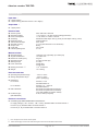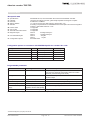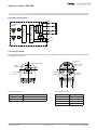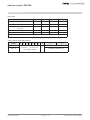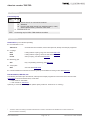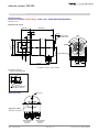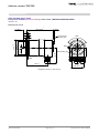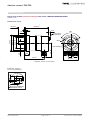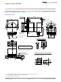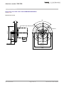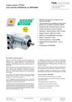
1
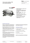
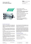
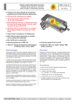
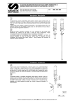
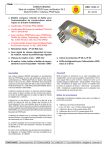
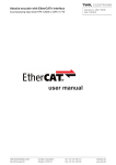
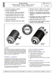
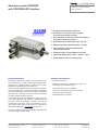
Absolute encoder TBD/TRD with PROFIBUS-DP interface Document no.: TRD 11868 KE Date: 30.04.2015 Singleturn and multiturn versions Contactless, wear-free sensor system according to the Hall principle High vibration and shock resistance thanks to the robust mechanical design Resolution up to 8192 steps / 360° (13 bit) Measuring range: 4096 revolutions (12-bit) Dual-chamber system to separate the rotor and electronics Protection type: IP 66, IP 69K (on request) Operating temperature range: - 40°C to + 85°C Preset button in the connecting cap Design and function Profibus characteristics Recording of the angular position and revolutions by means of Hall sensors - multiturn version with absolute transmission for up to 4096 revolutions - data output plus parameterisation and diagnosis via Profibus-DP. - Profibus-DP-V0 slave Robust housing manufactured from seawater-proof aluminium or stainless steel - stainless steel shaft - ball bearing with radial shaft seal - sensor circuit consisting of ASIC with Hall elements - electrical connections via the connecting cap with threaded cable connections. - Address and terminating resistors can be set in the connecting cap using DIP switches - Transmission rate of up to 12 MBaud - Reference value setting via the control system output data and preset button - Parameterisable via Profibus The absolute encoders are designed for direct connection to the PROFIBUS-DP. The interface is implemented with the SPC3 Siemens PROFIBUS controller. The protocol corresponds to DP-Slave Class 2 functionality in accordance with Profibus profile for encoders, No. 3.062, and is described in detail in the TRD 12770 user manual. The TRD is mechanicallly and electrically compatible with the electro-optical encoder CRD. TWK-ELEKTRONIK GmbH Heinrichstrasse 85 D-40041 Düsseldorf Postbox 10 50 63 Tel. +49 211 96117-0 Fax +49 211 637705 [email protected] www.twk.de Absolute encoder TBD/TRD Technical Data Input data * 4 bytes position 4 bytes velocity (firmware version 1.02 or higher) Output data * 4 bytes preset Electrical data n Sensor system: n Operating voltage: n Power consumption: n Auflösung: n Measuring range: nTotal number of steps: nAbsolute accuracy: n Output code: n Code path: n Internal updating time ASIC with HALL elements + 13.5 VDC to + 30 VDC (reverse voltage protection) < 2 W, switch on current < 250 mA Resolution:4096 steps / 360°<) (12-bit) or 8192 steps / 360°<) (13-bit) 4096 revolutions Max. 25-bit ± 0.2 % (with reference to one revolution) Binary CW / CCW ≤ 2 ms Mechanical data n Operating speed: n Angular acceleration: n Moment of inertia (rotor): n Operating torque: n Starting torque: n Perm. shaft load: n Bearing service life **: n Weight: 1000 rpm max. (optionally up to 4000 rpm) 105 rad/s² max. 20 gcm² ≤ 8 Ncm (at 500 rpm) ≤ 4 Ncm 250 N axial 250 N radial > 109 revolutions ca. 0.450 kg Environmental data Operating temperature range: Storage temperature range: Resistance: To shock: To vibration: EMC standards: Protection type: (DIN EN 60529) - 40°C to + 85°C - 20°C to + 60°C (due to packaging) 500 m/s²; 11 ms DIN EN 60068-2-27 500 m/s²; 10 ... 2000 Hz DIN EN 60068-2-6 EN 61000-6-2 (interference immunity) EN 61000-6-4 (interference emission) (only with shielded connection cables) IP 66, IP 69K (on request) Electrical connections Connecting cap with threaded cable connections for: Supply voltage (+ UB = 24 VDC, - UB = 0 VDC), threaded cable connection M12x1.5 Bus in (A, B), threaded cable connection M16x1.5 Bus out (A‘, B‘), threaded cable connection M16x1.5 * ** These values apply at maximum shaft load. Higher values are achievable at lower loads. From the point of view of the control system. Date: 30.04.2015 Page 2 of 12 Document no. TRD 11868 KE Absolute encoder TBD/TRD Technical Data Bus-specific data Specifications: Interface: Data rate: nStation address: GSD file: n Freeze-mode: Sync-mode: Automatic baud rate search: Diagnosis bytes User-Parameterbytes Configuration options: PROFIBUS-DP-V0, slave subscriber SPC3 Siemens PROFIBUS controller Line driver according to RS 485, galvanically separated via magnetic couplers 9.6 kBaud to 12 MBaud 1 to 126 can be set using DIP switches, default value: 123 According to Specifications for PROFIBUS Device Description and Device Integration Volume 1: GSD PNO-Order No: 2.122 Is supported Is supported Is supported Class 2: 63 diagnosis bytes * Class 1: 16 diagnosis bytes Class 2: 32 bytes Class 1: 2 bytes See table below Configuration options in accordance with PROFIBUS profile for encoders No. 3.062 Configuration Class Data Identifier byte Class 2 32 bit in/out 32 bit velocity 2 64 bit in/output data F3 Class 2 32 bit in/out 2 32 bit in/output data F1 Class 2 16 bit in/out 2 16 bit in/output data F0 Class 1 32 bit in 1 32 bit input data D1 Class 1 16 bit in 1 16 bit input data D0 Programmable parameters Parameter Value range Parameter description Code sense CW / CCW CW (clockwise): ascending values on rotation clockwise CCW (counter clockwise): descending values on rotation clockwise (viewed looking at the shaft) Scaling function disable / enable Enablement of the parameters of resolution and total number of steps Velocity unit Steps/10 ms, Steps/100 ms Only with firmware version 1.02 or higher Shortened diagnosis no / yes Reduction of the number of diagnosis bytes to 16 bytes Resolution [steps/360°] 1 ... 4096 (8192) Steps per revolution (360°) Total number of steps [steps] 1 ... 16,777,216 (33,554,432) singleturn version: 4096 (8192) Overall measuring range Reference value 0 ... total number of steps -1 (Programming is done via the output data) (The values in brackets apply to the TRDxx-xx8192R4096C2ZDxx) * Shortened diagnosis (16 bytes) can be set. Date: 30.04.2015 Page 3 of 12 Document no. TRD 11868 KE Absolute encoder TBD/TRD Electrical connection Principle circuit diagram VP N S ST N S B galvanic isolation Controller MT PROFIBUS Controller Hall - Sensor Magnet DC A DGND DC + VS - VS Connecting cap ZKD The cap is listed and supplied as a separate order item. It can be separated from the absolute encoder for setting purposes by releasing two screws. DIP switches Diagnosis LED‘s Sub D connector 15 pin socket Presetpushbutton UB SRD C Err TWK-ELEKTRONIK M3 mounting screws Connection terminal 1 DÜSSELDORF Connection terminal 1: 1 2 1 2 3 4 + UB A B A´ B´ Connection terminal 2 Connection terminal 2: Designation Signal Designation Signal UB+ Supply voltage (24 VDC) A RXD/TXD-N UB- GND (0 VDC) B RXD/TXD-P A' RXD/TXD-N B' RXD/TXD-P Date: 30.04.2015 Page 4 of 12 Document no. TRD 11868 KE Absolute encoder TBD/TRD Electrical connection Status-LEDs: Status UB SRD Incorrect configuration x x Impermissible parameters x Coding error (see diagnosis bytes 62 - 63) x Class 1 device configuration OK x x Class 2 device configuration OK x x C Err x x x x x UB - operating voltage, SRD - data transfer, C - class membership, Err - error message Address setting / terminating resistors: Switch 1 ON = 1 20 21 ... OFF = 0 2 3 4 5 6 Adresses 1 - 126 can be set (123: default adress) Date: 30.04.2015 7 8 27 9 10 Terminating resistors: on n.c. Terminating resistors: off Page 5 of 12 Document no. TRD 11868 KE Absolute encoder TBD/TRD Order number Absolute encoder TRD 58 - K A 4096 R 4096 C2 Z D 01 Electrical and / or mechanical variants * 01 Standard 02 Compatible with the encoder model KRD ** D PROFIBUS-DP-V0 Electrical connection: Z Connecting cap Profil: C2 Class 2 according to encoder profile No. 3.062 Measuring range: 4096 Revolutions Output code: R Binary Resolution: 4096 Steps / 360° 8192 Steps / 360° Housing material: A Aluminium S Stainless Steel 58 K KF KP KZ S SR ST 64 NZ 65 S SP 66 K KP 90 MP 105 M MP Flange: Clamped flange, shaft 10 mm with flat Clamped flange, shaft 10 mm with woodruff key Clamped flange, shaft 10 mm with parallel key (recommended for safety) Clamped flange, shaft for play-compensating toothed gear ZRS Synchro flange, shaft 6 mm Synchro flange, clamping shaft 12 mm (torque plate see accessories) Synchro flange, shaft 6 mm with flat Cam switch flange, shaft for ZRS Synchro flange, shaft 12 mm Synchro flange, shaft 12 mm with parallel key Clamped flange, shaft 10 mm with flat Clamped flange, shaft 10 mm with parallel key Mounting flange, shaft 12 mm with parallel key Mounting flange, shaft 12 mm Mounting flange, shaft 12 mm with parallel key Design form TBD TRD * Model: Singleturn encoder Multiturn encoder The basic versions according to the data sheet bear the number 01. Deviations are identified with a variant number and are documented in the factory. The speed value of the TRD is based on a 12 bit position value, but on a 16 bit position value in the KRD. ** The compatibility is only valid for the position value. Date: 30.04.2015 Page 6 of 12 Document no. TRD 11868 KE Absolute encoder TBD/TRD Order number Connecting cap ZKD - D 01 Electrical and / or mechanical variants * 01 Standard 34 Housing and cable glands from stainless steel (1.4305) without preset button, protection class IP 68 D PROFIBUS-DP-V0 ZKD Connecting cap for KRD / TRD absolute encoders Accessories Accessories (to be ordered separately) Documentation on CD TWK-CD-01 CD-ROM with documentation, device description file, bitmap and example programme Couplings BKK Folding bellows coupling, large, see data sheet BKK11840 BKM Folding bellows coupling, small, see data sheet BKM11995 KK14S Clamp coupling, see data sheet KK12301 Measuring gear ZRS Play compensating measuring gear ZRS11877 Torque plate ZMS See data sheet ZMS12939 Further installation accessories and securing clamps are available according to data sheet MZ10111 . Documentation, GSD file, etc. The following documents plus the GSD file, a bitmap and example programmes can be found in the Internet under www.twk.de in the documentation area, model TRD Data sheet No. TRD11868 User manual No. TRD12770 Optionally, a CD-ROM can be supplied. (Please specify article No. TWK-CD-01 on ordering.) * The basic versions according to the data sheet bear the number 01. Deviations are identified with a variant number and are documented in the factory. Date: 30.04.2015 Page 7 of 12 Document no. TRD 11868 KE Absolute encoder TBD/TRD Installation drawing Standard design Design form 58 with clamped flange, Order name: TRD58-KA4096R4096C2ZD01 Shaft ø 10 mm Dimensions in mm 83 ±0.5 * 30 ±0.5 3 6 ca. 5 Access to the preset button 120° M4x8 ca. 57 ø 10 f6 9 -0.1 ø 36 f8 ø 53 ø 58 +0.1 10 Shaft sealing ring ca. 64 * * singleturn version 14 mm shorter 48 ±0.1 3 N9 n Optional: Shaft "P" groove and parallel key 3 10 +0.2 Groove for parallel key DIN 6885-A 3x3x10 View of the cap Blind plug Diagnostic LED`s: See table on page 5 EMC threaded connections M16x1.5 Date: 30.04.2015 EMC-threaded connection M12x1.5 Page 8 of 12 Document no. TRD 11868 KE Absolute encoder TBD/TRD Installation drawing Other possible design forms Design form 58 with synchroniser flange, Order name: TRD58-SA4096R4096C2ZD01 Shaft ø 6 mm Dimensions in mm 89.5 ±0.5 * 14 ±0.5 ca. 5 3 Access to the preset button 120° M4x8 ca. 57 ø 6 f7 ø 50 f7 ø 58 +0.1 6 4 Shaft sealing ring ø50 ca. 71 * 42 ±0.1 * singleturn version 14 mm shorter Date: 30.04.2015 Page 9 of 12 Document no. TRD 11868 KE Absolute encoder TBD/TRD Installation drawing Design form 65 with synchroniser flange, Order name: TRD65-SA4096R4096C2ZD01 Shaft ø 12 mm Dimensions in mm 92 ±0.5 * 25 ±0.5 2 2.5 ca. 5 120° Access to the preset button M5x9 ø 45 f7 -0.1 ø 60 ø 64.5 1.5 ca. 57 ø 12 f7 Shaft sealing ring 18.5 ca. 74* 55 ±0.1 * singleturn version 14 mm shorter 4 N9 n Optional: Shaft "P" groove and parallel key 4 16 +0.2 12 Groove for parallel key DIN 6885-A 4x4x16 Date: 30.04.2015 Page 10 of 12 Document no. TRD 11868 KE Absolute encoder TBD/TRD Installation drawing Design form 58 with synchroniser flange and campled shaft, Order name: TRD58-SRA4096R4096C2ZD01 Shaft ø 12 mm (other shaft diameters on request) Dimensions in mm 89 ±0.5*** 18.8 ±0.5 ca. 5 3 6 4 70 ±0.1 Diagnosis LEDs Access to the preset button 120° ø 50 f7 ø 58 +0.1 * M4x8 Clamped shaft Di = 12 H7 Insertion: 16 mm EMC screw connections M12x1.5 EMC screw connections M16x1.5 ca. 57 Shaft sealing ring ø50 ca. 70.5*** 42 ±0.1 Clamp ring (Aluminium) (in scope of delivery) 30 8 15 Maximum shaft length circulation of the torque support arm = 23,2 mm +0,2 mm (as shown) PA locking washer Torque support arm (please order separatly) Ordering code: ZRH-A-12-X X = 6, 6,35, 8, 9,53, 10 19.5 ** Reducing bush (please order separatly) 8 X 12 7.2 9.3 Height adapter * 2x screws DIN 912 M4x30 (VA) plus 2x lock washer (VA) plus 2x washer DIN 9021-4.3. ** 3x screws DIN 912 M4x10 (VA) plus 3x lock washer (VA). *** singleturn version 14 mm shorter Date: 30.04.2015 Page 11 of 12 Document no. TRD 11868 KE Absolute encoder TBD/TRD Installation drawing Design form 105, Order name: TRD105-MA4096R4096C2ZD01 Shaft ø 12 mm Dimensions in mm 90° 10 Encoders with clamping flange ø 12 f7 ø 70 f7 M6x10 2.5 20 ±0.5 48 ±0.1 85 ±0.1 105 Date: 30.04.2015 Page 12 of 12 Document no. TRD 11868 KE