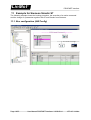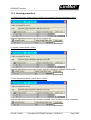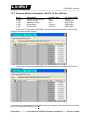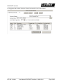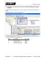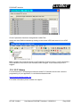
1
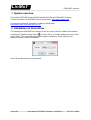
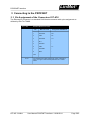
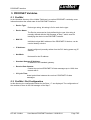
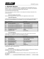
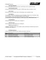
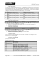
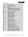
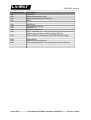
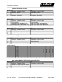
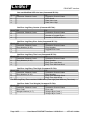
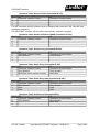
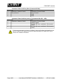
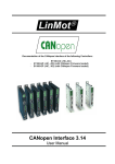
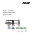
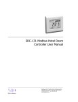
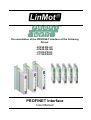
Documentation of the PROFINET Interface of the following Drives: - E1250-PN-UC - E1450-PN-QN - C1250-PN-XC - C1150-PN-XC PROFINET Interface User Manual LinMot PROFINET Interface © 2013 NTI AG This work is protected by copyright. Under the copyright laws, this publication may not be reproduced or transmitted in any form, electronic or mechanical, including photocopying, recording, microfilm, storing in an information retrieval system, not even for didactical use, or translating, in whole or in part, without the prior written consent of NTI AG. LinMot® is a registered trademark of NTI AG. Note The information in this documentation reflects the stage of development at the time of press and is therefore without obligation. NTI AG reserves itself the right to make changes at any time and without notice to reflect further technical advance or product improvement. Document version 6.1 / Whp, September 2014 Page 2/25 User Manual PROFINET Interface / 19/09/2014 NTI AG / LinMot PROFINET Interface LinMot Table of Content 1 SYSTEM OVERVIEW.................................................................................................................... 4 2 INSTALLATION ON SERVO DRIVE.......................................................................................... 4 3 CONNECTING TO THE PROFINET........................................................................................... 5 3.1.PIN ASSIGNMENT OF THE CONNECTORS X17-X18................................................................................... 5 4 PROFINET PARAMETERS........................................................................................................... 6 5 PROFINET VARIABLES............................................................................................................... 7 5.1.PROFINET.......................................................................................................................................... 7 5.2.PROFINET: SLOT CONFIGURATION......................................................................................................... 7 6 PROFINET MODULES.................................................................................................................. 8 7 STATE MACHINE........................................................................................................................ 17 8 PROFINET DIAGNOSIS.............................................................................................................. 17 9 ERROR CODES............................................................................................................................. 17 10 WARN WORD.............................................................................................................................. 17 11 EXAMPLE FOR SIEMENS SIMATIC S7................................................................................. 18 11.1.BUS CONFIGURATION (HW CONFIG).................................................................................................. 18 11.2.HOMING PROCEDURE........................................................................................................................ 19 11.3.EXECUTE MOTION COMMAND: VAI GO TO POS (010XH)................................................................... 20 11.4.CHANGE A PARAMETER OF THE DRIVE WITH THE PARAMETER CHANNEL MODULE...................................... 22 11.5.PLC LIBRARY................................................................................................................................ 23 12 RTROUBLESHOOTING............................................................................................................ 24 13 CONTACT ADDRESSES............................................................................................................ 25 NTI AG / LinMot User Manual PROFINET Interface / 19/09/2014 Page 3/25 LinMot PROFINET Interface 1 System overview The LinMot PROFINET drives E1250-PN and E1450-PN are PROFINET-IO slaves. Further information on PROFINET can be found under: http://www.profibus.com Programming examples provided by LinMot are listed under: http://www.linmot.com/index.php?id=141 2 Installation on Servo Drive For installing the PROFINET-IO firmware on the servo drive, start the LinMot-Talk software and press the install firmware button . Choose the file “Firmware_Buildxxxxxxxx.sct” and press “Open“. The wizard will guide you through the installation. When asking for the interface software choose “PROFINET”: Press ok and follow the rest of the wizard. Page 4/25 User Manual PROFINET Interface / 19/09/2014 NTI AG / LinMot LinMot PROFINET Interface 3 Connecting to the PROFINET 3.1. Pin Assignment of the Connectors X17-X18 The Ethernet/IP connector is a standard RJ45 female connector with a pin assignment as defined by EIA/TIA T568B: X17 – X18 RealTime Ethernet Connector Pin RJ-45 NTI AG / LinMot Wire color code Assignment 100BASE-TX 1 WHT/ORG Rx+ 2 ORG Rx- 3 WHT/GRN Tx+ 4 BLU - 5 WHT/BLU - 6 GRN Tx- 7 WHT/BRN - 8 BRN - case - - Use standard patch cables (twisted pair, S/UTP, AWG26) for wiring. This type of cable is usually referred to as a “Cat5eCable”. User Manual PROFINET Interface / 19/09/2014 Page 5/25 LinMot PROFINET Interface 4 PROFINET Parameters The PROFINET Servo drives have an additional parameter tree branch, which can be configured with the distributed LinMot-Talk software. With these parameters, the PROFINET behaviour can be configured. The software LinMot-Talk can be downloaded from http://www.linmot.com under the section download, software & manuals. Dis-/Enable With the Dis-/Enable parameter the LinMot servo drive can be run without the PROFINET going online. So in first step the system can be configured and run without any bus connection. PROFINET Interface\ Dis-/Enable Disable Servo drive runs without PROFINET. Enable Servo drive runs only with a PROFINET connection. Byte Order Defines the used byte order. PROFINET Interface\ Byte/Word Order\Byte Order Reversed Byte order is reversed. For S7 PLCs select reversed. Not reversed Byte order is not reversed. Word Order Defines the used word order. PROFINET Interface\ Byte/Word Order\Word Order Reversed Word order is reversed. For S7 PLCs select reversed. Not reversed Word order is not reversed. MC CMD Intf Par Order Defines the used parameter word order. PROFINET Interface\ Byte/Word Order\MC CMD Intf Par Order Reversed Order is reversed. CMD Header - Par word 1 - Par word 0 - Par word 3 - Par word 2 - etc... Not reversed Order is not reversed. CMD Header - Par word 0 Par word 1 - Par word 2 - Par word 3 - etc... Diagnose Priority Defines the behaviour of the diagnostic telegram. PROFINET Interface\ Diagnose Priority None Only minimal diagnostic data is transmitted. Low The diagnostic data is sent as status information only. High The diagnostic data is sent with high priority in the error state. Monitoring Channels Defines the source variable by UPID of the four monitoring channels. PROFINET Interface\ Monitoring Channels Channel 1 UPID Source UPID for Monitoring Channel 1 Channel 2 UPID Source UPID for Monitoring Channel 2 Channel 3 UPID Source UPID for Monitoring Channel 3 Channel 4 UPID Source UPID for Monitoring Channel 4 Page 6/25 User Manual PROFINET Interface / 19/09/2014 NTI AG / LinMot LinMot PROFINET Interface 5 PROFINET Variables 5.1. ProfiNet In the Variables directory of the LinMot-Talk there is a section \PROFINET containing some information about the actual state of the PROFINET interface: • Device Type: • Device Name: • MAC ID: • IP Address: • Net Mask: • Standard Gateway IP Address: IP address of the standard gateway. • Receive Data Counter: Counts the received PROFINET-IO data messages up to 1000, then restarts with 0. • IO Cycle Time: Actual period time between the received PROFINET-IO data messages. Device type string, this string is fix for each device type. The Device name can be freely defined by the user, this string is normally defined with the HW manager of Step 7 and is used for identifying the device in the PROFINET network. Individual unique MAC address of the PROFINET-IO device, can be used to identify a device. Actual configured (normally written from the PLC during power up) IP address. Net mask for the IP address. 5.2. ProfiNet: Slot Configuration In this directory the configured modules for the Slots 1..7 are displayed. The configuration of the modules is done in the HW manager of the Step 7. NTI AG / LinMot User Manual PROFINET Interface / 19/09/2014 Page 7/25 LinMot PROFINET Interface 6 PROFINET Modules The LinMot drive is a PROFINET-IO slave. To configure it with a PROFINET master, the GSD file is used. You can find the GSD file LINM092D.GSD in the LinMot-Talk installation directory (typically C:\Program Files\LinMot\LinTalk-Talk 4 Build xxxxxxxx\Firmware\PROFINET\GSD). There are the following modules defined, to be configured according the demands of the desired application: Default IO mapping with Config With the data configured in this module, most of the applications could be solved. Output Data Mapping In this real time IO mapping the 16 bit control word, the 16 bit motion command header and the motion command parameters are exchanged. The size of this mapping is 32 bytes. Byte Offset Description Size/Type 00h 02h 04h 08h 0Ch 10h 14h 18h 1Ah 1Ch MC SW_ControlWord MC SW_MotionCommandHeader MC SW_MotionCommandPar Bytes 00..03 MC SW_MotionCommandPar Bytes 04..07 MC SW_MotionCommandPar Bytes 08..11 MC SW_MotionCommandPar Bytes 12..15 MC SW_MotionCommandPar Bytes 16..19 Cfg Module Control Word Cfg Module Index/.. Cfg Module Value/.. Uint16 / Bit coded Uint16 / 12Bit Command 4Bit count nibble Uint32 / Command specific Uint32 / Command specific Uint32 / Command specific Uint32 / Command specific Uint32 / Command specific Uint16 Uint16 Uint32/Sint32 Input Data Mapping In this real time IO mapping the StateVar for the main state machine and several other helpful data are exchanged. The size of this mapping is 26 bytes. Byte Offset Description Size/Type 00h 02h 04h 06h 0Ah 0Eh 12h 14h 16h MC SW StateVar MC SW StatusWord MC SW WarnWord MC SW DemandPosition MC SW ActualPosition MC SW DemandCurrent Cfg Module Status Word Cfg Module Index/.. Cfg Module Value/.. Uint16 / coded state depending Uint16 / Bit coded Uint16 / Bit coded Int32 / Position [100nm] Int32 / Position [100nm] Int32 / Current [1mA] Uint16 Uint16 Uint32/Sint32 The use of the Control word and Motion Command interface is described in [1]. The real time configuration module is described in [2]. Control/Status This module should always be configured. It contains the Control and Status word, which are described in the document “User Manual Motion Control Software”. MC Cmd Interface This maps the MC Command interface of the drive. Please refer to the documentation of the MC software. Page 8/25 User Manual PROFINET Interface / 19/09/2014 NTI AG / LinMot LinMot PROFINET Interface Get Actual Position Returns the actual position of the motor. (32 Bit integer value, resolution 0.1µm) Get Demand Position Returns the demand position of the motor. (32 Bit integer value, resolution 0.1µm) Get Current Returns the set current of the motor. (32 Bit integer value, resolution 1mA) Get StateVar The StateVar consists of the MainState and the SubState. Please refer to the table “State Var” on chapter 3 of the “User Manual Motion Control Software”. The StateVar has all relevant flags and information for clean handshaking within one word and can therefore replace the modules “Get MC Header Echo” and “Get Error Code”. Get WarnWord Returns the Warn Word. Please refer to chapter 10. Get ErrorCode Returns the Error Code. Please refer to chapter 9. Monitoring Channel 1..4 Transmits cyclically the value of the variable, which is defined by the Monitoring Channel Parameter (see chapter 4). NC Setpoint Values With this setpoint module the axis could be connected to a NC axis. Byte Offset Description Size/Type 00h 04h 08h Streamed Position Setpoint Streamed Velocity Setpoint Streamed Acceleration Setoint Int32 / Position [100nm] Int32 / Velocity [1um/s] Int32 / Velocity [10um/s^2] NTI AG / LinMot User Manual PROFINET Interface / 19/09/2014 Page 9/25 LinMot PROFINET Interface Real Time Config The Real Time Config module allows access to parameters, variables, curves, error log and command table. Also restart, start and stop of the drive is possible. Of course the Parameter Channel module works independently from the MC Cmd Interface. For this reason changing a parameter and sending a motion command can be done in parallel. Word 1. 2. DO Parameter Channel Control Argument (meaning depends on Cmd ID) Argument (meaning depends on Cmd ID) Argument (meaning depends on Cmd ID) 3. 4. DI Parameter Channel Status Argument (meaning depends on Cmd ID) Argument (meaning depends on Cmd ID) Argument (meaning depends on Cmd ID) Real Time Config Control Parameter Command ID to be executed 15 14 13 12 11 10 Reserved 9 8 7 6 Command Count 5 4 3 2 1 0 The Parameter Channel Control is split in two parts: • Parameter Command ID to be executed (bits 8-15), see table Command ID • Command Count (bits 0-3) Real Time Config Status Parameter Status 15 14 13 Reserved 12 11 10 9 8 7 6 5 4 Command Count Response 3 2 1 0 The Parameter Channel Status is split in two parts: • Parameter Status (bits 8-15), see table Parameter Status • Command Count Response (bits 0-3) Command Count A new command is only evaluated, if the value of the command count changes. In the easiest way bit 0 can be toggled. Parameter Command ID This selects the command. Possible Commands are: Command ID Description 00h No Operation Parameter Access 10h Read ROM Value of Parameter by UPID 11h Read RAM Value of Parameter by UPID 12h Write ROM Value of Parameter by UPID 13h Write RAM Value of Parameter by UPID 14h Write RAM and ROM Value of Parameter by UPID 15h Get minimal Value of Parameter by UPID 16h Get maximal Value of Parameter by UPID 17h Get default Value of Parameter by UPID Page 10/25 User Manual PROFINET Interface / 19/09/2014 NTI AG / LinMot PROFINET Interface LinMot Parameter (UPID) List 20h Start Getting UPID List 21h Get next UPID List item 22h Start Getting Modified UPID List 23h Get next Modified UPID List item Stop / Start / Default 30h Restart drive 31h Set parameter ROM values to default (OS SW) 32h Set parameter ROM values to default (MC SW ) 33h Set parameter ROM values to default (Interface SW) 34h Set parameter ROM values to default (Application SW) 35h Stop MC and Application Software (for Flash access) 36h Start MC and Application Software Curve Service 40h Save all Curves from RAM to Flash 41h Delete all Curves (RAM) 50h Start Adding Curve (RAM) 51h Add Curve Info Block (RAM) 52h Add Curve Data (RAM) 53h Start Modifying Curve (RAM) 54h Modify Curve Info Block (RAM) 55h Modify Curve Data (RAM) 60h Start Getting Curve (RAM) 61h Get Curve Info Block (RAM) 62h Get Curve Data (RAM) Error Log 70h Get Error Log Entry Counter 71h Get Error Log Entry Error Code 72h Get Error Log Entry Time low 73h Get Error Log Entry Time high 74h Get Error Code Text Stringlet Command Table 80h Command Table: Save to Flash 81h Command Table: Delete All Entries (RAM) 82h Command Table: Delete Entry 83h Command Table: Write Entry 84h Command Table: Write Entry Data 85h Command Table: Get Entry 86h Command Table: Get Entry Data 87h Get Presence List of Entries 0..31 from RAM 88h Get Presence List of Entries 32..63 from RAM 89h Get Presence List of Entries 64..95 from RAM 8Ah Get Presence List of Entries 96..127 from RAM 8Bh Get Presence List of Entries 128..159 from RAM 8Ch Get Presence List of Entries 160..191 from RAM 8Dh Get Presence List of Entries 192..223 from RAM 8Eh Get Presence List of Entries 224..255 from RAM NTI AG / LinMot User Manual PROFINET Interface / 19/09/2014 Page 11/25 LinMot PROFINET Interface Parameter Status 00h 02h 04h 05h Description OK, done Command Running / Busy Block not finished (Curve Service) Busy C0h C1h C2h C3h C5h C6h UPID Error Parameter Type Error Range Error Address Usage Error Error: Command 21h “Get next UPID List item” was executed without prior execution of “Start Getting UPID Lis” End of UPID List reached (no next UPID List item found) D0h D1h D4h Odd Address Size Error (Curve Service) Curve already defined / Curve not present (Curve Service) Page 12/25 User Manual PROFINET Interface / 19/09/2014 NTI AG / LinMot LinMot PROFINET Interface Word 1. 2. 3. 4. Overview Parameter access: DO Parameter Channel Control Parameter UPID Parameter Value Low Parameter Value High DI Parameter Channel Status Parameter UPID Parameter Value Low Parameter Value High Word 1. 2. 3. 4. Overview Curve access: DO Parameter Channel Control Curve Number Data Value Low / Info Block size Data Value High / Data Block size DI Parameter Channel Status Curve Number Data Value Low / Info Block size Data Value High / Data Block size Word 1. 2. 3. 4. Start getting UPID List: DO Parameter Channel Control Start UPID (search from this UPID) - DI Parameter Channel Status - Word 1. 2. 3. 4. Get next UPID List item: DO Parameter Channel Control - DI Parameter Channel Status UPID found Address Usage - Word 1. 2. 3. 4. Life Parameter 11 10 9 8 7 6 5 4 RAM Read 12 RAM Write 13 ROM Read 14 ROM Write 15 calculationNot used for Hash Address Usage: 3 2 1 0 Start getting Modified UPID List (Command ID 22h): DO DI Parameter Channel Control Parameter Channel Status Start UPID (search from this UPID) - NTI AG / LinMot User Manual PROFINET Interface / 19/09/2014 Page 13/25 LinMot PROFINET Interface Word 1. 2. 3. 4. Get next Modified UPID List item (Command ID 23h): DO DI Parameter Channel Control Parameter Channel Status UPID found Data Value Low Data Value High Word 1. 2. 3. 4. Get Error Log Entry Counter (Command ID 70h): DO DI Parameter Channel Control Parameter Channel Status Number of Logged Errors Number of Occurred Errors Word 1. 2. 3. 4. Get Error Log Entry Error Code (Command ID 71h): DO DI Parameter Channel Control Parameter Channel Status Entry Number (0..20) Entry Number Logged Error Code - Word 1. 2. 3. 4. Get Error Log Entry Time Low (Command ID 72h): DO DI Parameter Channel Control Parameter Channel Status Entry Number (0..20) Entry Number Entry Time Low Word Entry Time Mid Low Word Get Error Log Entry Time High (Command ID 73h): Word DO DI 1. Parameter Channel Control Parameter Channel Status 2. Entry Number (0..20) Entry Number 3. Entry Time Mid High Word 4. Entry Time High Word The Error Log Entry Time consists of 32Bit hours (Time High) and 32Bit ms (Time Low). Word 1. 2. 3. 4. Get Error Code Text Stringlet (Command ID 74h): DO DI Parameter Channel Control Parameter Channel Status Error Code Error code Stringlet Number (0..7) Stringlet Byte 0 and 1 Stringlet Byte 2 and 3 Page 14/25 User Manual PROFINET Interface / 19/09/2014 NTI AG / LinMot PROFINET Interface LinMot Command Table: Save to Flash (Command ID 75h): Word DO DI 1. Parameter Channel Control Parameter Channel Status 2. 3. 4. For this command, the MC software must be stopped (with command “35h: Stop MC and Application Software”). The PROFINET Interface will stay active while the MC software is stopped. Word 1. 2. 3. 4. Command Table: Delete All Entries (RAM) (Command ID 81h) DO DI Parameter Channel Control Parameter Channel Status - Word 1. 2. 3. 4. Command Table: Delete Entry (Command ID 82h): DO DI Parameter Channel Control Parameter Channel Status Entry Number Entry Number - Word 1. 2. 3. 4. Command Table: Write Entry (Command ID 83h) DO DI Parameter Channel Control Parameter Channel Status Entry Number Entry Number Block Size (even number of bytes) Block Size - Word 1. 2. 3. 4. Command Table: Write Entry Data (Command ID 84h) DO DI Parameter Channel Control Parameter Channel Status Entry Number Entry Number Data Data Data Data Word 1. 2. 3. 4. Command Table: Get Entry (Command ID 85h) DO DI Parameter Channel Control Parameter Channel Status Entry Number Entry Number Block Size - NTI AG / LinMot User Manual PROFINET Interface / 19/09/2014 Page 15/25 LinMot Word 1. 2. 3. 4. Word 1. 2. 3. 4. PROFINET Interface Command Table: Get Entry Data (Command ID 86h) DO DI Parameter Channel Control Parameter Channel Status Entry Number Entry Number Data Data Command Table: Get Entry List (0..7) (Command IDs 87h .. 8Eh) DO DI Parameter Channel Control Parameter Channel Status Offset in bytes Bit field (Bit set= undefined / Bit cleared = used) Bit field (Bit set= undefined / Bit cleared = used) Further documentation on how to configure a drive by fieldbus and handle curves can be found on the additional manual “Parameterization of LinMot SG5 servo drives over Fieldbus Interfaces”. Page 16/25 User Manual PROFINET Interface / 19/09/2014 NTI AG / LinMot LinMot PROFINET Interface 7 State Machine Please refer to “User Manual Motion Control Software”. 8 PROFINET Diagnosis The LinMot drive supports 12 bytes of diagnostic data. The diagnosis telegram is according the following table: Byte 0..5 6..7 8..9 10..11 Description Data according PROFINET-IO standard Extended Diagnosis Header and stuffing Warn Word (see chapter 10 for description) Error Code (see chapter 9 for description) 9 Error Codes Please refer to “User Manual Motion Control Software” for the Error Codes of the MC Software. The PROFINET Interface has the following additional Error Codes: Error Code Hexadecimal C1h C2h C3h Error Description Fatal Error: drive not supported Config Error: Invalid MACID IO Err: Connection lost 10 Warn Word Please refer to “User Manual Motion Control Software”. NTI AG / LinMot User Manual PROFINET Interface / 19/09/2014 Page 17/25 LinMot PROFINET Interface 11 Example for Siemens Simatic S7 The following example shows the homing procedure, the execution of a motion command and the change of a parameter together with S7 and Simatic from Siemens: 11.1. Bus configuration (HW Config) Page 18/25 User Manual PROFINET Interface / 19/09/2014 NTI AG / LinMot LinMot PROFINET Interface 11.2. Homing procedure 1. Release lock state: Control Word = 0000h (Only needed if StateVar MainState is 00h) : StateVar MainState becomes 02h: Ready to Switch On 2. Homing: Control Word = 083Fh StateVar MainState becomes 09h: Homing, Homing is finished if SubState becomes 0Fh 3. Enter Operational State: Control Word = 003Fh StateVar MainState becomes 08h: Operation Enabled, Drive is ready for motion commands NTI AG / LinMot User Manual PROFINET Interface / 19/09/2014 Page 19/25 LinMot PROFINET Interface 11.3. Execute Motion Command: VAI Go To Pos (010xh) Name Header 1. Par 2. Par 3. Par 4. Par Description VAI Go To Pos (010xh) Target Position: Maximal Velocity: Acceleration: Deceleration: Scaled Value 257 50mm 1m/s 10m/s^2 10m/s^2 Int. Value (HEX) 0101h 0007A120h 000F4240h 000F4240h 000F4240h In the case of \Parameters\PROFINET Interface\Byte/Word Order\MC CMD Intf Par Order\not reversed (default setting): In the case of \Parameters\PROFINET Interface\Byte/Word Order\MC CMD Intf Par Order\ reversed: To send the next command the count nibble has to be changed. The header for the next VAI Go To Pos command is therefore 0100h. Page 20/25 User Manual PROFINET Interface / 19/09/2014 NTI AG / LinMot PROFINET Interface LinMot As it appears with LinMot-Talk after “Read Command” in the Control Panel: NTI AG / LinMot User Manual PROFINET Interface / 19/09/2014 Page 21/25 LinMot PROFINET Interface 11.4. Change a parameter of the drive with the Parameter Channel Module Example: Change the “Maximal Current” (UPID 13A6h) over PROFINET while firmware is running Add module Parameter Channel [4 Word DI/DO] As Command ID use 13h “Write RAM Value of Parameter by UPID”, Command Count 1 The UPID of “Maximal Current” is 13A6h. The internal scaling of the current value is 0.001A: 3A (Scaled) = 3000 (Int) = 0000088Bh (HEX) Word 1. 2. 3. 4. Page 22/25 Description Parameter Channel Control Parameter UPID Parameter Value Low Parameter Value High Value (Hex) 1301h 13A6h 088Bh 0000h User Manual PROFINET Interface / 19/09/2014 NTI AG / LinMot LinMot PROFINET Interface Check if parameter has been changed with LinMot-Talk. Add a new User Defined variable by clicking on the button UPID and search for the UPID 13A6h Hint: Consider the Command Count in the Parameter Channel Control. A new command is only evaluated, if the value of the command count changes. In the easiest way bit 0 is toggled. 11.5. PLC Library For the Siemens S7 developing environment exists PLC libraries which could ease the programming of your application, it could be downloaded under: http://linmot2.dynalias.net/plc_lib/ For further information please contact our support. NTI AG / LinMot User Manual PROFINET Interface / 19/09/2014 Page 23/25 LinMot PROFINET Interface 12 Troubleshooting If the PROFINET connection is not working, proceed as followed: - Is the correct firmware installed on the drive? When installing the firmware the PROFINET interface must be selected. The actual firmware and configuration software can always be downloaded from http://www.linmot.com - Check if the correct GSD file is used (LINM092D.GSD, which is provided together with LinMot4Talk 4 in the subdirectory. \firmware\PROFINET\GSDML). Page 24/25 User Manual PROFINET Interface / 19/09/2014 NTI AG / LinMot LinMot PROFINET Interface 13 Contact Addresses --------------------------------------------------------------------------------------------------------------------------SWITZERLAND NTI AG Haerdlistr. 15 CH-8957 Spreitenbach Sales and Administration: +41-(0)56-419 91 91 [email protected] Tech. Support: +41-(0)56-544 71 00 [email protected] Tech. Support (Skype) : skype:support.linmot Fax: Web: +41-(0)56-419 91 92 http://www.linmot.com -------------------------------------------------------------------------------------------------------------------------USA LinMot, Inc. 204 E Morrissey Dr. Elkhorn, WI 53121 Sales and Administration: 877-546-3270 262-743-2555 Tech. Support: 877-804-0718 262-743-1284 Fax: 800-463-8708 262-723-6688 E-Mail: Web: [email protected] http://www.linmot-usa.com -------------------------------------------------------------------------------------------------------------------------Please visit http://www.linmot.com to find the distribution near you. Smart solutions are… NTI AG / LinMot User Manual PROFINET Interface / 19/09/2014 Page 25/25