1
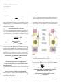
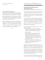
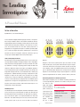
January
2007
No 6
A Powerful Vision
To See or Not to See
By Rob Kimura, Leica Product Manager
As the evolution of digital photomicrography continues, new generations of high-resolution cameras have become available for forensic
imaging. Digital camera technology is mainly driven by the consumer
market where ‘the more pixels the better’ is the status quo. In recent
years the consumer market has seen color cameras jump from 1.3
megapixels to 12 megapixels and higher. A common question people
ask is, “How much higher will camera resolution get?” But the real
question for forensic investigators should be, “What do I gain by
using a high-resolution digital camera on my microscope?”
2 pixels across
each line pair
Understanding Image Formation
2 pixels per line pair
shifted 1/2 pixel
Ideal: ≥ 3 pixels
per line pair
Diagram 1
Due to the physics of the image formation process, even a perfect microscope objective will blur two adjacent objects into a single object
Diagram 1, with at least 3 pixels per line pair, the camera can now
when placed close enough together. One way to consider this ‘limit-
detect the line pairs, even if pixels shift to the left or right. It is impor-
ing resolution’ is to image a repeating pattern of adjacent black and
tant to note that further increasing the number of pixels can lead to
white lines. When the number of ‘line pairs’ per millimeter (lp/mm) is
‘over-sampling’, where the additional pixels per line pair provide no
increased beyond the optical resolution limit of the microscope, the
gain in spatial information. However, the transition to over-sampling
image will no longer form lines, but instead will form a uniform gray
depends on the wavelength of light used, the objective’s numerical
background. In addition to blurring an image, an objective lens also
aperture, magnification to the camera, and the camera’s pixel size.
magnifies an object. At the camera, this translates into an image
spread across a larger area whenever magnification is greater than
Determining Resolution as Defined by Line Pairs
1x. Also, a microscope may be configured with intermediate optical
With simple assumptions, we can estimate the limiting resolution for
components to change the net magnification to the camera; for the
a microscope objective, determine the number of line pairs across
purposes of this article, we will assume that the microscope has a 1x
the field of view
magnification c-mount attachment.
(FOV), and compare
this to the number of
Contents
How Many Pixels?
pixels covering the
One would expect that the ideal pixel correlation would place 2 pixels
same distance for a
across each line pair so that one pixel can detect the white line and
A Powerful Vision. . . . . . . . . . . . . page 1
given camera. There
the other pixel the black line. However, this pixel ratio can produce a
Comparison Illumination. . . . . . . page 3
are many mathemat-
gray result because pixels can be placed between the white and
ical definitions for
black lines. To resolve all line pairs in all cases, there must be at least
optical
3 pixels per line pair. As you can see in the ideal case shown in
(R), but a simple
resolution
continued on page 2
1
Industry News. . . . . . . . . . . . . . . . page 5
Glossary. . . . . . . . . . . . . . . . . . . . . . page 5
A Powerful Vision
continued from page 1
approximation is:
Color Camera
λAperture (NA) Lens
R = λ / 2 Numerical
R=
A pixel in a color (Bayer Matrix) camera performs two functions,
of the light in nanometers (nm)
where λ is the wavelength2(NA)
where λ is the wavelength of the light in nanometers (nm)
spatial sampling of the image and measuring the intensity for a
This relationship indicates that when using a high NA lens and white
Consequently, it takes more pixels (approximately 25% more per line
light illumination, the smallest resolvable distance is about 300nm or
pair) to obtain the same resolution as a monochrome camera.
0.3µm. In terms of line pairs per mm at a mid wavelength of the visible
Required color camera resolution = (4 pixels/lp) => 23 megapixels
specific position of the spectrum, e.g., red, green, and blue.
light spectrum, green 550nm:
Optical Resolution (lp/mm) = NA x 3000
Optical Resolution (lp/mm) = NA x 3000
To calculate the number of line pairs required to cover the objective’s
FOV, calculate the area visible through the lens by dividing the FOV of
your microscope (let’s assume 22mm) by the magnification factor.
A 5x objective allows you to observe an area of 4.4mm φ
22mm FOV
= 4.4mm
5
A 50x objective allows you to observe an area of
only less than 0.5mm φ
22mm FOV = 0.44mm
50
So how many line pairs can be observed with a 5x objective? Simply
multiply the visible area by the optical resolution to calculate the FOV.
But please note that there is one caveat in calculating FOV. While a
microscope objective forms a circular image, a camera sensor is
typically square or rectangular. If the FOV for the microscope is
22mm, then the FOV of the sensors reduced by the square root of 2.
Diagram 2
Example: Using a 5x objective with a .15 NA and a 22mm FOV
4.4
√2
In the above example, the lens is capable of better resolution
= 3.1mm
than today’s high-resolution cameras can capture.
At higher magnification, a lower megapixel camera is required.
Achievable Optical Resolution = 0.15 x 3000 = 450 lp/mm
Lets take a 50x, 0.85 NA objective with a square FOV as an example:
Line pairs covering camera sensor = 3.1mm x 450 lp/mm = 1400 lp
(22mm
50x )
= 0.31mm
Monochrome Camera
√ 2
The monochrome camera presents an ideal case as every pixel contributes equally to the resolution. The number of pixels required to
capture every bit of spatial information coming from the objective is:
Achievable Optical Resolution = 0.85 NA x 3000 = 2550 lp/mm
Pixels across line pair = 1400 lp x 3 pixels/lp = 4200 pixels
Line pairs covering the camera’s sensor =
Camera resolution is specified in terms of the total number of pixels,
0.31mm x 2550 lp/mm = 790 lp
so assuming a rectangular 4:3 format, the number of pixels needed
Required
monochrome
camera
resolution
pixels/lp)
Note that
as optical
magnification
increases,
the(3 number
of pixels
=
>
4.2
megapixels
needed to match the optical resolution decreases.
for ideal digital image quality is:
4200 pixels x 3150 pixels = 13 megapixels
Required color camera resolution (4 pixels/lp) = >7.5 megapixels
2
continued on page 3
Comparison Illumination
A Powerful Vision
continued from page 2
Achieving the Best Illumination for Your
Comparison Microscope
by Wayne Buttermore, Leica Marketing Manager, Forensic Microscopy
Do I Need a High-Resolution Digital Camera?
One of the biggest challenges in comparison microscopy is balancing
Now let’s get back to our original question. High-resolution, 8-plus
color and intensity of the light sources between the two microscopes.
megapixel cameras provide a resolution benefit at low magnification.
Unlike reflected light applications the transmitted light comparison
But as magnification increases, they provide less of an advantage.
microscope has many more variables, that affect both illumination
What is optimum depends on what kind of imaging you are doing.
intensity and color balance.
More pixels will increase the size of the image file. As the number of
pixels increases, each pixel is typically smaller, which results in
The setup of a compound microscope for diffraction-limited examina-
reduced dynamic range and light sensitivity.
tion of trace evidence is best achieved by setting up Koehler illumination. Experienced microscopists can reproducibly establish the
Going beyond 8 megapixels makes sense for very low magnifications
settings for the field and aperture diaphragms on an individual
typically used in comparison forensic macroscopy, if the entire
microscope to achieve the best resolution and contrast for a sample.
available FOV is used. But even with fewer pixels, adjusting the
However, when a second microscope is added to the system, match-
magnification to the camera with an intermediate optic accessory
ing the setup becomes far more complex.
such as a 1x magnification c-mount, you can match the camera to
the microscope’s resolution across a limited field of view.
First, let’s look at the different illumination types that are used for
comparison microscopy:
❖❖❖
1. Two separate lamphouses controlled by separate power
supplies: This was a common illumination setup found on older
comparison microscopes from American Optical, Leitz,
and Leeds. Pre 1980
2. Two separate lamphouses controlled by separate power
supplies with continuous variable filter systems in the
illumination path (Leica Variolux®): Leitz and Leica used this
configuration for many years on comparison systems using
the Laborlux, Dialux, Dialux 20, DM R, and DM4000 microscope
platforms. 1980’s to present
3. Randomized bifurcated fiber optic light guides from a single
cold light source (150W or 250W): Adapted to the illumination
path in place of standard halogen light bulb sources.
Mid 1980’s to present
A microscope is designed with many optical elements apart from the
illumination source that affect color. As light travels through the
microscope, it passes through a collecting lens, diffuser, field
diaphragm, glass cover for the light exit port, filter holder for colored
glass or interference filters, aperture diaphragm, condenser element,
slide, mounting media with sample, coverglass … and finally to the
objective, eyetube lens, and eyepieces. Each of these components
can be responsible for changing the light path, intensity, and color of
the light passing through the optical system.
In the design and manufacture of modern comparison microscopes,
care is taken to select matching optical components to reduce these
continued on page 4
3
Comparison Illumination
continued from page 3
influences by decreasing manufacturing tolerances and ensuring
adjustable color to the illumination path on each microscope. With
that components originate from the same production lot. Ideally,
practice, it provides a perfect match of color and intensity during
this leaves only lamp intensity, condenser height position, and
side-by-side examinations.
field and aperture diaphragm settings as variables to contend with.
In systems having a Leica Variolux® adjustable filter device, the
Procedure for Adjusting Variolux®
1. When starting, be sure to re-
process of balancing illumination and color is simplified.
move any colored filters from
How do I ensure balanced intensity and color?
the optical path.
Initially it is critical to set up the two light sources as uniformly as
this means neutralizing the
possible:
Variolux by turning the filters to
1. Prepare two identical slides with slides and coverglass from
Essentially
the open position. It is easiest
the same box. Place a slide on each microscope stage.
to accomplish this by observing
2. Place the comparison bridge in the side-by-side image mode.
the field of view and turning
3. Select the 10x objective for each microscope.
each color filter control. If col-
Color filter wheel
a. When using a two-lamphouse system, adjust lamp intensity
or is added while turning the
so the voltage is the same for both sides. Adjust the collector
knob, reverse direction until it reaches the stop position. This
lens for each lamphouse so that intensity and homogeneity
needs to be completed on both microscopes. If any colors were
of the field of view is as uniform as possible.
introduced by the Variolux during initial illumination setup as
b. In microscopes with bifurcated fiber optic systems, adjust
described above, repeat the illumination setup.
lamp intensity to a comfortable level for the objective in use.
If intensity or homogeneity is not consistent, rotate the fiber
2. Carefully examine the color of the light on each microscope side.
bundle at its interface with the microscope. Then secure it
Keep in mind the complimentary color. If a yellow tint is viewed on
in place. Intensity can be influenced by moving the fiber
one side, the addition of an equal amount of blue would be
optic guide forward or backward in the mount.
required to offset the effect. If the color match gets worse as the
process continues, start over.
4. Be sure to remove any colored glass filters, polarizers or
polarization compensators from the light path.
5. Remove the first two slides from step 1, and place two new
3. When any component in the optical path is changed, such as the
slides, each having a sample and coverglass, on the stage
sample, objective or aperture setting, you may need to readjust the
of each of the microscopes.
Variolux.
6. Establish Koehler illumination by
setting the condenser height,
Balancing illumination intensity and color takes practice. It is much
centering the field diaphragm, and
easier to set up a system for visual examination. A camera system,
adjusting the aperture diaphragm to
whether 35mm or digital, is far more sensitive to color and density
differences than the human eye, so fine tuning the camera may still
match the objective in use. (Leica
users can refer to the Leica DM R
Figure 49: establish Koehler
illumination
be necessary.
user manual, Figure 49.) Discussion
Next issue: Achieving the best illumination for your digital camera
of Koehler illumination is outside the scope of this article.
❖❖❖
In microscopes with a bifurcated illumination system, these steps
should be all that is required to obtain visually balanced light intensity
and color.
Two Lamphouse Systems:
Systems having two light sources and Variolux continuous illumination control may require further adjustment. A Variolux contains three
independent filter controls for continuous introduction of red, green
or blue filters with increasing gradients. This introduces infinitely
4
Industry News
Glossary
The AAFS (American Academy of Forensic Sciences) will hold
Koehler Illumination: A characteristic feature of the light path
its 59th Annual Scientific Meeting on February 19-24, 2007 at the
provided by all high-quality microscopes is the consistent imaging of
Henry B. Gonzalez Convention Center in San Antonio, Texas.
the “luminous spot on the light source” and the “illuminated field”
The Academy's annual scientific meeting presents over 500 scientific
through all imaging stages of the microscope, from the light source to
papers, breakfast seminars, workshops, and other special events.
the final image. These conditions are met when the field and aperture
The AAFS represents a wide range of forensic specialties.
diaphragm, positions in the microscope light path are conjugated
More information: www.aafs.org
to the object plane and to the rear focal plane of the objective,
respectively.
The 38th annual AFTE Training Seminar will take place at the Hyatt
Regency, San Francisco, California on May 27-June 1, 2007. AFTE
White Point: A white point is one of a number of reference illumi-
welcomes everyone to this beautiful city and to what promises to be
nants used in Colorimetry, which serve to define the color "white".
a fantastic training conference. The host committee comprises not
Depending on the application, different definitions of white are
only the San Francisco Police Department – Firearms and Toolmark
needed to give acceptable results.
Unit, but also firearms examiners from various agencies all over
Northern California such as Contra Costa County Sheriff’s Office,
Color Temperature: Visible light is commonly described by its color
Santa Clara County, Fresno DOJ, Sacramento DOJ, BATFE-Walnut
temperature. A traditional incandescent light source's color tempera-
Creek, Sacramento County, and Oakland PD.
ture is determined by comparing its hue with a theoretical, heated,
More information: www.afte.org
black-body radiator. The lamp's color temperature is the temperature, measured in kelvins, at which the heated black-body radiator
The 2007 ASQDE Meeting will be held on August 11-16, 2007 at the
matches the hue of the lamp. Color temperature is sometimes used
Boulder, CO Millennium Harvest House. More information will be
loosely to mean "white balance" or “white point”.
provided as it becomes available: www.asqde.org
Line Pairs Resolution: Line “pairs” are often used to measure
The 2007 Annual Meeting of the Southern Association of Forensic
resolution instead of lines. A line pair is a pair of adjacent dark and
Scientists will be on September 9-14, 2007 in Atlanta. A full program
light lines; while a line counts both dark lines and light lines. A resolu-
is planned including Advanced Structure Elucidation (DI), LC Tandem
tion of 5 line pairs per mm means 5 dark lines alternating with 5 light
MS use in Post-mortem Cases, and Statistics in DNA Analysis.
lines, or 10 lines per mm.
More information: www.southernforensic.org
❖❖❖
❖❖❖
Editorial Staff
Editor-in-Chief:
Managing Editors:
Graphic Design:
Contributing Editor:
Molly Lundberg
Pam Jandura, Wayne Buttermore
M.N. Kennedy
Rob Kimura
Note: We are interested in your comments and thoughts about the newsletter. Please
feel free to email your comments to [email protected].
5