1
Freescale Semiconductor
Application Note
Document Number: AN3384
Rev. 0, 12/2006
Interfacing a Hard Drive to an
M5249C3 Board
by: Fabio Estevam
Latin America
1
Introduction
Contents
1
In the embedded scenario it is popular to employ
hard-disk drives (HDDs) for many applications such as
media players, network-attached storage (NAS), TV
content recorders, etc. Many HDD models are available
in small footprint, high-density, and low-power suited
for embedded applications. The MCF5249, MCF5250,
and MCF5251 have an integrated IDE block that allows
them to interface to standard HDDs with minimum
external hardware.
This application note shows how to interface an HDD to
an M5249C3 running uClinux IDE as the operational
system. Installing uClinux, the appropriate toolchain,
and how to use uClinux support for HDDs, and how to
configure the VFAT file system are also explained.
After reading this application note, you should be able to
install the uClinux package and toolchain and configure
the kernel for a M5249C3 board; enable IDE support in
uClinux for the M5249C3; build an uClinux image and
download it to a M5249C3 board; and access the hard
disk content from the M5249C3 board.
© Freescale Semiconductor, Inc., 2006. All rights reserved.
Introduction . . . . . . . . . . . . . . . . . . . . . . . . . . . . . . . . . . . 1
1.1 Processor Description . . . . . . . . . . . . . . . . . . . . . . . 2
1.2 Evaluation Board . . . . . . . . . . . . . . . . . . . . . . . . . . . 3
2
Building the Application . . . . . . . . . . . . . . . . . . . . . . . . . 3
2.1 System Requirements . . . . . . . . . . . . . . . . . . . . . . . 3
2.2 uClinux Installation Process . . . . . . . . . . . . . . . . . . 4
3
IDE Interface . . . . . . . . . . . . . . . . . . . . . . . . . . . . . . . . . 12
3.1 IDE Hardware . . . . . . . . . . . . . . . . . . . . . . . . . . . . 12
3.2 IDE Signals Description. . . . . . . . . . . . . . . . . . . . . 13
3.3 IDE Register Programming . . . . . . . . . . . . . . . . . . 14
3.4 IDE-Related Files in uClinux . . . . . . . . . . . . . . . . . 16
3.5 Mount Process. . . . . . . . . . . . . . . . . . . . . . . . . . . . 16
4
Conclusion. . . . . . . . . . . . . . . . . . . . . . . . . . . . . . . . . . . 17
5
References . . . . . . . . . . . . . . . . . . . . . . . . . . . . . . 17
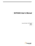
Introduction
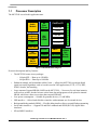
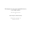
1.1
Processor Description
The MCF5249 is used in this application note.
Audio
Module
8K
Byte
i-Cache
ColdFire V2
I Addr Gen
I Fetch
PLL
Frequency
Synthesizer
96K
Byte
SRAM
QSPI
B
u
s
C
o
n
t
r
o
l
Instr Buf
Dec & Sel Op
A Gen & Ex
12-bit ADC
IDE
Interface
Flash
Media
Interface
DUART
EMAC
Timers
H/W Divide
GPIOs
I²Cs
Debug
Module
SDRAM
Cntr
& Chip
Selects
DMAs
Figure 1. MCF5249 Block Diagram
Processor description and key features:
• The MCF5249 comes in two packages:
– 144-pin QFP — Runs up to 120 MHz
– 160-pin BGA — Runs up to 140 MHz
• Enhanced multiply and accumulate (eMAC) unit — Allows the MCF5249 to perform digital
signal processing algorithms such as vocoders used in VoIP applications (G.729, G.723), MP3,
WMA, decoder, and encoding
• Large amount of internal SRAM (96 KB on the MCF5249) — Necessary for real-time intensive
tasks such as an MP3 decoder because critical time data and programs can be placed in internal
SRAM, which has a faster access time than external SDRAM
• Low-power consumption — Suitable for portable devices (1.3 mW/MHz)
• IDE interface — Allows hard-disk-drive interface with minimum use of external devices.
• Background-debug module (BDM) — Flexible debug interface allows external flash programming
• Serial audio interfaces — Support I2S and EIAJ standards and SPDIF(IEC958) digital audio
interfaces.
• SD and MMC interfaces
Interfacing a Hard Drive to an M5249C3 Board, Rev. 0
2
Freescale Semiconductor
Building the Application
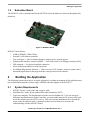
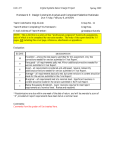
1.2
Evaluation Board
The M5249C3 is the evaluation board for the MCF5249 and is the hardware referred to throughout this
document.
Figure 2. M5249C3 Board
M5249C3 main features:
• 8 MB of SDRAM, 2 MB of flash
• External 10/100 ethernet controller
• Two serial ports — One for monitor firmware output, one for general purpose
• Debug module interface connector (BDM) — Used with source level debuggers running on PCs
• IDE connector — Or glueless hard-disk connection
• Stereo audio inputs and stereo audio input jacks
• Pre-flashed dBug monitor firmware — Allows access to CPU registers, memory content, and it
downloads applications to the target from the serial port and over the ethernet
2
Building the Application
The following sections show how to set up the application’s working environment for the application and
how to build and download a uClinux image with IDE and telnet support to the M5249C3.
2.1
•
•
•
System Requirements
M5249C3 board, a serial cable, and crossover cable
Hard-disk drive with a 40-pin standard IDE cable formatted as FAT32
Linux host computer. The distribution used in the tests was RedHat 9.0™, but you can run in
different Linux distributions. In the Linux host, you must enable network-file system (NFS) and
trivial file transfer protocol (TFTP) services. This varies among distributions but is beyond the
scope of this document to teach. A terminal emulator such as minicon is necessary for
communicating with the M5249C3 board.
Interfacing a Hard Drive to an M5249C3 Board, Rev. 0
Freescale Semiconductor
3
Building the Application
2.2
uClinux Installation Process
Installing uClinux on the host machine:
Download the latest uClinux distribution: http://www.uclinux.org/pub/uClinux/dist/. This document was
written when the latest version was uClinux-dist-20051110. The current version is uClinux-dist 20060803.
The former is a full source package containing kernel 2.0, 2.4, and 2.6 libraries and application code.
1. Download the toolchain for ColdFire® products
(http://www.uclinux.org/pub/uClinux/m68k-elf-tools/). m68k-elf-tools-20030314 is used in this
application note. It contains the cross-compiler and assembler for ColdFire targets.
2. As root, install the toolchain in the Linux Host sh m68k-elf-tools-20030314.
3. Log in as a standard user.
4. Copy the uClinux source package file uClinux-dist-200511110.tar.gz into /home/user (in my case,
my name follows: /home/fabio).
5. Go to /home/user directory and extract tar –xzvf uClinux-dist-200511110.tar.gz.
2.2.1
Generating an uClinux Image and Downloading It to the Target
After the toolchain and uClinux distribution are installed in the host computer, build an image for the
M5249C3 then download it to the board.
1. First, configure the kernel and target options. Go to uClinux-dist directory and then:
>> cd /home/user/uClinux-dist
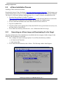
>> make menuconfig.
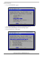
2. Go to Vendor/Product Selection, then <Select>. The following window should appear:
Interfacing a Hard Drive to an M5249C3 Board, Rev. 0
4
Freescale Semiconductor
Building the Application
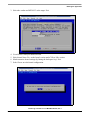
3. Select the vendor and M5249C3 as the target. Exit.
4.
5.
6.
7.
Go to Kernel/Library/Default Selection.
Select kernel linux-2.4.x as the kernel version and uC-lib as Libc version.
Mark customize kernel settings (by hitting the backspace key). Exit.
Select Yes to save the kernel configuration.
Interfacing a Hard Drive to an M5249C3 Board, Rev. 0
Freescale Semiconductor
5
Building the Application
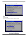
8. Go to ATA/IDE/MFM/RLL support.
9. Select ATA/IDE/MFM/RLL. Go to IDE, ATA, and ATAPI block devices.
10. Select enhanced IDE/MFM/RLL disk/cdrom/tape/floppy support.
11. Select include IDE/ATA-2 DISK support.
Interfacing a Hard Drive to an M5249C3 Board, Rev. 0
6
Freescale Semiconductor
Building the Application
12. Scroll down the menu. Select uClinux IDE interface support.
13. Exit.
14. Exit.
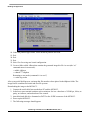
15. Go to file systems.
16. Under the file systems menu, select VFAT (Windows 95) fs support.
17. Scroll down the file systems menu. Go to partition types option.
Interfacing a Hard Drive to an M5249C3 Board, Rev. 0
Freescale Semiconductor
7
Building the Application
18. Under the partition types menu, select advanced partition selection.
19. Exit.
20. Exit.
21. Exit.
22. Select Yes for saving new kernel configuration.
23. Create a folder called /tftboot that contains the generated image.bin file. As root (the “su”
command enters in root mode):
>>mkdir /tftpboot
>>chmod 777/tftpboot
Returning to user mode (command is “su user”)
>> make dep; make
After a successful build process, an image.bin file must have been placed in the/tftpboot folder. The
image.bin file combines the kernel and root-file systems.
Downloading the image to the M5249C3:
1. Connect the serial cable between the host PC and the M5249C3.
2. In the host, run a terminal emulator such as minicon. Set it to a baud rate of 19200 bps, 8 bits, no
parity, no software, and no hardware flow control.
3. Attach the hard disk drive formatted as FAT32 to the J8 IDE connector of the M5249C3.
4. Power up the M5249C3.
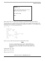
5. The following messages should appear:
Interfacing a Hard Drive to an M5249C3 Board, Rev. 0
8
Freescale Semiconductor
Building the Application
Hard Reset
DRAM Size: 8M
ColdFire MCF5249 EVS Firmware v3a. 1b. 1c
(Build 4 on Mar 04 2003 15:38:14)
Enter “help” for help.
dBuG>
Refer to the M5249C3 User Manual for a detailed list of commands the dBug monitor supports.
Ensure the tftp service is enabled and that the /tftpboot folder can be exported. The tftp package is not
installed by default in RedHat 9.0™ and other Linux distributions. In RedHat 9.0™, the configuration file
for the tftp server is /etc/xinetd.d/tftp (listed below):
service tftp
{
disable= no
socket_type
protocol
wait
user
server
server_args
per_source
cps
flags
= dgram
= udp
= yes
= root
= /usr/sbin/in.tftpd
= -s /tftpboot
= 11
= 100 2
= IPv4
}
Insert a crossover cable between the host PC and the M5249C3 board.
NOTE
You can use a normal cable to connect the PC and the M5249C3 in a
network. By default, the DHCP application is enabled for the M5249C3,
and the board can retrieve an IP address if the network has DHCP server
capabilities.
In dBug prompt, type “show”
dBug>set server 192.168.0.1
dBug>set client 192.168.0.2
Interfacing a Hard Drive to an M5249C3 Board, Rev. 0
Freescale Semiconductor
9
Building the Application
In the host: ifconfig eth0 192.168.0.1
dBug>dn –i image.bin
This command requests a TFTP transfer and sends the image.bin file located at /tftpboot folder from the
host.
The image transferred through TFTP is now placed in the external SDRAM of the M5249C3. To execute
the uClinux kernel, jump to its initial location 0x20000. The command in dBug is:
dBug> go 20000
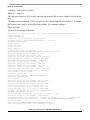
The kernel boot message should start:
Linux version 2.4.31-uc0 (root@localhost) (gcc version 2.95.3 20010315 (release)(ColdFire patches 20010318 from http://fi6
uClinux/COLDFIRE(m5249)
COLDFIRE port done by Greg Ungerer, [email protected]
Flat model support (C) 1998,1999 Kenneth Albanowski, D. Jeff Dionne
On node 0 totalpages: 2048
zone(0): 0 pages.
zone(1): 2048 pages.
zone(2): 0 pages.
Kernel command line:
Calibrating delay loop... 92.56 BogoMIPS
Memory available: 5992k/8192k RAM, 0k/0k ROM (850k kernel code, 229k data)
kmem_create: Forcing size word alignment - mm_struct
kmem_create: Forcing size word alignment - filp
Dentry cache hash table entries: 1024 (order: 1, 8192 bytes)
Inode cache hash table entries: 512 (order: 0, 4096 bytes)
kmem_create: Forcing size word alignment - inode_cache
Mount cache hash table entries: 512 (order: 0, 4096 bytes)
kmem_create: Forcing size word alignment - bdev_cache
kmem_create: Forcing size word alignment - cdev_cache
kmem_create: Forcing size word alignment - kiobuf
Buffer cache hash table entries: 1024 (order: 0, 4096 bytes)
Page-cache hash table entries: 2048 (order: 1, 8192 bytes)
POSIX conformance testing by UNIFIX
Linux NET4.0 for Linux 2.4
Based upon Swansea University Computer Society NET3.039
Initializing RT netlink socket
Starting kswapd
kmem_create: Forcing size word alignment - file_lock_cache
kmem_create: Forcing size word alignment - nfs_read_data
kmem_create: Forcing size word alignment - nfs_write_data
ColdFire internal UART serial driver version 1.00
ttyS0 at 0x100001c0 (irq = 73) is a builtin ColdFire UART
ttyS1 at 0x10000200 (irq = 74) is a builtin ColdFire UART
M5249AUDIO: (C) Copyright 2002, Greg Ungerer ([email protected])
M5249AUDIO: DMA channel=0, irq=120
Bad boy: audio(DMA) (at 0x0007fe4c) called request_irq without a dev_id!
kmem_create: Forcing size word alignment - blkdev_requests
SMSC LAN91C111 Driver (v2.0), (Linux Kernel 2.4 + Support for Odd Byte) 09/24/01 by Pramod Bhardwaj
(pramod.bhardwaj@)eth0: SMC91C11xFD(rev:1) at 0xe0000300 IRQ:166 MEMSIZE:8192b NOWAIT:0 ADDR:
00:cf:52:49:c3:04
SLIP: version 0.8.4-NET3.019-NEWTTY (dynamic channels, max=256).
CSLIP: code copyright 1989 Regents of the University of California.
Interfacing a Hard Drive to an M5249C3 Board, Rev. 0
10
Freescale Semiconductor
Building the Application
Blkmem copyright 1998,1999 D. Jeff Dionne
Blkmem copyright 1998 Kenneth Albanowski
Blkmem 1 disk images:
0: 12E084-20BC83 [VIRTUAL 12E084-20BC83] (RO) <ROMFS>
RAMDISK driver initialized: 16 RAM disks of 4096K size 1024 blocksize
PPP generic driver version 2.4.2
PPP MPPE compression module registered
Uniform Multi-Platform E-IDE driver Revision: 7.00beta4-2.4
ide: Assuming 50MHz system bus speed for PIO modes; override with idebus=xx
hda: probing with STATUS(0x50) instead of ALTSTATUS(0x7f)
hda: QUANTUM FIREBALL ST2.5A, ATA DISK drive
hdb: probing with STATUS(0x00) instead of ALTSTATUS(0x7f)
hdb: probing with STATUS(0x00) instead of ALTSTATUS(0x7f)
ide0 at 0x50000020 on irq 165
hda: attached ide-disk driver.
hda: 5008752 sectors (2564 MB) w/81KiB Cache, CHS=4969/16/63
Partition check:
hda: [PTBL] [621/128/63] hda1
NET4: Linux TCP/IP 1.0 for NET4.0
IP Protocols: ICMP, UDP, TCP
kmem_create: Forcing size word alignment - ip_dst_cache
IP: routing cache hash table of 512 buckets, 4Kbytes
TCP: Hash tables configured (established 512 bind 512)
NET4: Unix domain sockets 1.0/SMP for Linux NET4.0.
FAT: bogus logical sector size 49376
VFS: Mounted root (romfs filesystem) readonly.
Freeing unused kernel memory: 28k freed (0x112000 - 0x118000)
Shell invoked to run file: /etc/rc
Command: hostname uClinux
Command: /bin/expand /etc/ramfs.img /dev/ram1
Command: mount -t proc proc /proc
mount: bb_xasprintf: Unknown error 0
pid 9: failed 256
Command: mount -t ext2 /dev/ram1 /var
Command: mkdir /var/tmp
Command: mkdir /var/log
Command: mkdir /var/run
Command: mkdir /var/lock
Command: mkdir /var/empty
Command: ifconfig lo 127.0.0.1
Command: route add -net 127.0.0.0 netmask 255.0.0.0 lo
Command: dhcpcd -p -a eth0 &
[13]
Command: cat /etc/motd
Welcome to
____ _ _
/ __| ||_|
_
_| | | | _ ____ _
_ _ _
| | | | | | || | _ \| | | |\ \/ /
| |_| | |__| || | | | | |_| |/
\
| ___\____|_||_|_| |_|\____|\_/\_/
| |
|_|
For further information check:
http://www.uclinux.org/
Interfacing a Hard Drive to an M5249C3 Board, Rev. 0
Freescale Semiconductor
11
IDE Interface
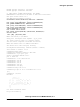
Command:
Execution Finished, Exiting
Sash command shell (version 1.1.1)
/>
Highlighted above are the messages related to the IDE detection. The IDE vendor and model are shown as
well as the number of sectors and disk size.
You can now manually set up the board’s IP address by “> ifconfig eth0 192.168.0.2”.
NOTE
If a cross cable connects the M5249C3 to a network, you can retrieve an IP
address through DHCP. The uClinux default setting enables the DHCP
daemon.
You can try to ping the host: “ping 192.168.0.1”. Press CTRL-C to stop the ping process.
/> ifconfig eth0 192.168.0.2
/< ping 192.168.0.1
PING 192.168.0.1 (192.168.0.1): 59 data bytes
64 bytes from 192.168.0.1: icmp_seq=0 ttl=64 time=5.9 ms
64 bytes from 192.168.0.1: icmp_seq=1 ttl=64 time=2.9 ms
64 bytes from 192.168.0.1: icmp_seq=2 ttl=64 time=2.9 ms
64 bytes from 192.168.0.1: icmp_seq=3 ttl=64 time=2.9 ms
64 bytes from 192.168.0.1: icmp_seq=4 ttl=64 time=2.9 ms
--- 192.168.0.1 ping statistics --5 packets transmitted, 5 packets received, 0% packet loss
round-trip min/avg/max = 2.9/3.5/5.89 ms
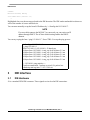
3
IDE Interface
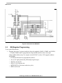
3.1
IDE Hardware
J9 is a standard 2X20 IDE connector. These signals are involved in IDE connection:
Interfacing a Hard Drive to an M5249C3 Board, Rev. 0
12
Freescale Semiconductor
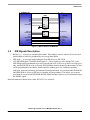
IDE Interface
MCF5249
Buffer
IDE 40-pin
header
IDE_A0
IDE_A1
IDE_A2
IDE_CS0
IDE_CS1
A1
A2
A3
A4
A5
BUFENB2
/OE
DIR
Buffer
IDE_D[15:0]
D[31:16]
BUFENB2
R/W
/OE
DIR
GPO
IDEIORDY
IDEIOR
IDEIOW
GPIO
IDE_RESET
IDE_IOCHRDY
IDE_IOR
IDE_IOW
IDE_IRQ
Figure 3. IDE Connection to M5249C3
3.2
•
•
•
IDE Signals Description
BufEn2_b — Active-low external buffer enable. This enable is inactive when CS0 is active and
should enable a buffer for peripheral devices except boot ROM.
IDE-Iordy — Active-high ready indication from IDE device to MCF5249.
CS2/IDE-DIOR/gpio13 and IDE-DIOW/gpio14 —These signals go active during CS2 cycles.
IDE-DIOR can be programmed to go active on read and write cycles or to go active on read cycles
only, and IDE-DIOW on write cycles only. IDE-DIOR has features identical to the normal CS2 and
can be programmed for an address location and for masking, port size, and burst capability
indication, wait state generation, and internal/external termination. You can also enable IDE-DIOR
and IDE-DIOW to access an IDE drive or another AT-bus peripheral. This allows you to insert
more than 16 wait states on IDE-DIOR and IDE-DIOW and have dynamic-cycle termination using
the IORDY signal.
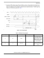
Detailed schematics shown below (from M5249C3 User Manual):
Interfacing a Hard Drive to an M5249C3 Board, Rev. 0
Freescale Semiconductor
13
IDE Interface
Figure 4. Schematics from M5249C3
3.3
IDE Register Programming
To set up the IDE interface:
1. Program chip-select-2 registers inside the chip-select modules (CSAR2, CSMR2, and CSCR2).
— CSAR2, CSMR2 must be programmed to map the IDE interface in the correct part
of the ColdFire address map. For example: in the M5249C3 we have CS2 mapped at address
0x50000000.
— CSCR2 bit fields must be programmed as follows:
— AA: 0 (TA signal generated by IDEconfig2 register logic)
— WS[3:0]: not relevant
— PS[1:0]: 10 (16 bit port size)
— BSTR, BSTW: 00 (no burst read/write cycles)
— BEM: not relevant
Interfacing a Hard Drive to an M5249C3 Board, Rev. 0
14
Freescale Semiconductor
IDE Interface
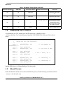
2. Program the IDE config1 register. Relevant fields are cs2pre, cs2post, bufen1cs2en, bufen2cs2en.
The values required for the buffer enable signals (bufen1cs2en, and bufen2cs2en) depend on the
hardware configuration. If two buffers are used in cascade, both bits must be 1. Fields cs2pre and
cs2post are relevant and explained in Table 1.
Figure 5. IDE Timing Diagram
Table 1. IDE-Related Timing Signals
ATA Timing Symbol
t1
t2
ATA4 Value
25
70
Controlled by Setting
Equation (Approximately)
Comments
cs2pre > t1 – tbuf
tbus is external buffer enable
time. cs2pre must be set
high enough to provide
sufficient address-to-DIOR,
DIOW setup time. Typical
cs2pre values range from 3
to 5 SCLK clocks.
(waitCount2 + 4)T > t2
t2 is the DIOR, DIOW low
period. To meet 70 ns t2
period, waitCcount2 must be
set to 3.
cs2pre
waitCount2
Interfacing a Hard Drive to an M5249C3 Board, Rev. 0
Freescale Semiconductor
15
IDE Interface
Table 1. IDE-Related Timing Signals (continued)
ATA Timing Symbol
ATA4 Value
Controlled by Setting
t5a
50
waitCount2
tA
35
waitCount2
tR
0
—
t9
10
cs2post
3.4
Equation (Approximately)
Comments
(waitCount2 + 1.5)T > tA +tio
To meet this timing,
waitCount2 must be set to
4–5.
(waitCount2 + 1.5)T > tA +tio
To meet this timing,
waitCount2 must be set to
3–4.
3T > tbuf + tdel – tR
tdel: time difference between
path from IORDY and from
read data. Read data in
device must be valid 3 clocks
after IORDY going high.
cs2post >t9
To meet this timing, typical
value for cs2post is 10 nS.
IDE-Related Files in uClinux
As shown below, the CS2, which acts as the IDE chip select, is initially set up at
../uClinux-dist/linux-2.4.x/arch/m68knommu/platform/5249/FREESCALE/crt0_ram.S file as shown
below:
/*
*
Setup CS2 for IDE interface.
*/
move.l
#0x50000000, %d0
/* CS2 mapped at
0x50000000 */
move.l
%d0, 0x98(%a0)
move.l
#0x001f0001, %d0
/* CS2 size of 1MB
*/
move.l
%d0, 0x9c(%a0)
move.w
#0x0080, %d0
/* CS2 = 16bit, TA */
move.w
%d0, 0xa2(%a0)
move.l
move.l
move.l
move.l
#0x00107020, %d0
%d0, 0x18c(%a1)
#0x000c0400, %d0
%d0, 0x190(%a1)
/* IDEconfig1 */
/* IDEconfig2 */
Find the IDE driver at ../uClinux-dist/linux-2.4.x/drivers/ide/
3.5
Mount Process
Before the M5249C3 board can access the hard-disk-file system, send the following command in uClinux:
> mount –t vfat /dev/hda1 /mnt
Interfacing a Hard Drive to an M5249C3 Board, Rev. 0
16
Freescale Semiconductor
Conclusion
After this command, HDD content is mounted at the /mnt folder.
> cd /mnt
If you want the IDE mount process to be executed automatically at startup, append the following line:
“mount –t vfat /dev/hda1 /mnt” to the end of this file: .../uClinux-dist/vendors/Generic/big/rc.
4
Conclusion
This application note showed how to interface an HDD with an M5249C3 evaluation board running
uClinux. The hardware interface is straightforward due to a built-in MCF5249 IDE controller, the IDE
driver, and file-system support. The file-system support is available in uClinux for the M5249C3 board;
therefore, you can add your own application that needs an HDD interface.
5
References
1. MCF5249 ColdFire Integrated Microprocessor User Manual
2. M5249C3 Reference Board User Manual
3. MP3 Decoder on uClinux Demo User Manual
Interfacing a Hard Drive to an M5249C3 Board, Rev. 0
Freescale Semiconductor
17
THIS PAGE IS INTENTIONALLY BLANK
Interfacing a Hard Drive to an M5249C3 Board, Rev. 0
18
Freescale Semiconductor
Interfacing a Hard Drive to an M5249C3 Board, Rev. 0
Freescale Semiconductor
19
How to Reach Us:
Home Page:
www.freescale.com
E-mail:
[email protected]
USA/Europe or Locations Not Listed:
Freescale Semiconductor
Technical Information Center, CH370
1300 N. Alma School Road
Chandler, Arizona 85224
+1-800-521-6274 or +1-480-768-2130
[email protected]
Europe, Middle East, and Africa:
Freescale Halbleiter Deutschland GmbH
Technical Information Center
Schatzbogen 7
81829 Muenchen, Germany
+44 1296 380 456 (English)
+46 8 52200080 (English)
+49 89 92103 559 (German)
+33 1 69 35 48 48 (French)
[email protected]
Japan:
Freescale Semiconductor Japan Ltd.
Headquarters
ARCO Tower 15F
1-8-1, Shimo-Meguro, Meguro-ku,
Tokyo 153-0064
Japan
0120 191014 or +81 3 5437 9125
[email protected]
Asia/Pacific:
Freescale Semiconductor Hong Kong Ltd.
Technical Information Center
2 Dai King Street
Tai Po Industrial Estate
Tai Po, N.T., Hong Kong
+800 2666 8080
[email protected]
For Literature Requests Only:
Freescale Semiconductor Literature Distribution Center
P.O. Box 5405
Denver, Colorado 80217
1-800-441-2447 or 303-675-2140
Fax: 303-675-2150
[email protected]
Document Number: AN3384
Rev. 0
12/2006
Information in this document is provided solely to enable system and software
implementers to use Freescale Semiconductor products. There are no express or
implied copyright licenses granted hereunder to design or fabricate any integrated
circuits or integrated circuits based on the information in this document.
Freescale Semiconductor reserves the right to make changes without further notice to
any products herein. Freescale Semiconductor makes no warranty, representation or
guarantee regarding the suitability of its products for any particular purpose, nor does
Freescale Semiconductor assume any liability arising out of the application or use of any
product or circuit, and specifically disclaims any and all liability, including without
limitation consequential or incidental damages. “Typical” parameters that may be
provided in Freescale Semiconductor data sheets and/or specifications can and do vary
in different applications and actual performance may vary over time. All operating
parameters, including “Typicals”, must be validated for each customer application by
customer’s technical experts. Freescale Semiconductor does not convey any license
under its patent rights nor the rights of others. Freescale Semiconductor products are
not designed, intended, or authorized for use as components in systems intended for
surgical implant into the body, or other applications intended to support or sustain life,
or for any other application in which the failure of the Freescale Semiconductor product
could create a situation where personal injury or death may occur. Should Buyer
purchase or use Freescale Semiconductor products for any such unintended or
unauthorized application, Buyer shall indemnify and hold Freescale Semiconductor and
its officers, employees, subsidiaries, affiliates, and distributors harmless against all
claims, costs, damages, and expenses, and reasonable attorney fees arising out of,
directly or indirectly, any claim of personal injury or death associated with such
unintended or unauthorized use, even if such claim alleges that Freescale
Semiconductor was negligent regarding the design or manufacture of the part.
Freescale™ and the Freescale logo are trademarks of Freescale Semiconductor, Inc.
All other product or service names are the property of their respective owners.
© Freescale Semiconductor, Inc. 2006. All rights reserved.
RoHS-compliant and/or Pb-free versions of Freescale products have the functionality
and electrical characteristics as their non-RoHS-compliant and/or non-Pb-free
counterparts. For further information, see http://www.freescale.com or contact your
Freescale sales representative.
For information on Freescale’s Environmental Products program, go to
http://www.freescale.com/epp.