1
Instruction Set Simulator
User’s Guide
Version 1.3
Fifth Edition (September 2002)
This edition of Instruction Set Simulator User’s Guide applies to IBM Instruction Set Simulator Version 1.3 and all
the subsequent versions of the simulator until otherwise indicated in new versions or technical newsletters.
The following paragraph does not apply to the United Kingdom or any country where such
provisions are inconsistent with local law: INTERNATIONAL BUSINESS MACHINES CORPORATION
PROVIDES THIS DOCUMENT “AS IS” WITHOUT WARRANTY OF ANY KIND, EITHER EXPRESSED OR
IMPLIED, INCLUDING, BUT NOT LIMITED TO, THE IMPLIED WARRANTIES OF MERCHANTABILITY AND
FITNESS FOR A PARTICULAR PURPOSE. Some states do not allow disclaimer of express or implied
warranties in certain transactions; therefore, this statement may not apply to you. In no event will IBM be liable
for damages arising directly or indirectly from any use of the information contained in this document.ë
IBM does not warrant that the content of this publication or the accompanying source code examples, whether
individually or as one or more groups, will meet your requirements or that the publication or the accompanying
source code examples are error-free.
This publication could contain technical inaccuracies or typographical errors. Changes are periodically made to
the information herein; these changes will be incorporated in new editions of the publication. IBM may make
improvements and/or changes in the product(s) and/or program(s) described in this document at any time.
It is possible that this publication may contain references to, or information about, IBM products (machines and
programs), programming, or services that are not announced in your country. Such references or information
must not be construed to mean that IBM intends to announce such IBM products, programming, or services in
your country. Any reference to an IBM licensed program in this publication is not intended to state or imply that
you can use only IBM’s licensed program. You can use any functionally equivalent program instead.
No part of this publication may be reproduced or distributed in any form or by any means, or stored in a data
base or retrieval system, without the written permission of IBM.
Requests for copies of this publication and for technical information about IBM products should be made to your
IBM Authorized Dealer or your IBM Marketing Representative.
All information contained in this document is subject to change without notice. The products described in this
document are NOT intended for use in applications such as implantation, life support, or other hazardous uses
where malfunction could result in death, bodily injury, or catastrophic property damage. The information
contained in this document does not affect or change IBM product specifications or warranties. Nothing in this
document shall operate as an express or implied license or indemnity under the intellectual property rights of
IBM or third parties. All information contained in this document was obtained in specific environments, and is
presented as an illustration. The results obtained in other operating environments may vary.
While the information contained herein is believed to be accurate, such information is preliminary, and should
not be relied upon for accuracy or completeness, and no representations or warranties of accuracy or
completeness are made.
You may also address written comments about this publication to:
IBM Corporation
Department YM5A
P.O. Box 12195
Research Triangle Park, NC 27709
IBM may use or distribute whatever information you supply in any way it believes appropriate without incurring
any obligation to you.
© Copyright IBM Corp. 2002 International Business Machines Corporation 1999, 2002. All rights reserved.
Printed in the United States of America
4321
Notice to U.S. Government Users-Documentation Related to Restricted Rights-Use, duplication,.or disclosure is
subject to restrictions set forth in GSA ADP Schedule Contract with IBM Corporation.
ii
Instruction Set SImulator User’s Guide
Patents and Trademarks
IBM may have patents or pending patent applications covering the subject matter in this publication. The
furnishing of this document does not give you any license to these patents. You can send license inquiries, in
writing, to the IBM Director of Licensing, IBM Corporation, 208 Harbor Drive, Stamford, CT 06904, United States
of America.
The following terms are trademarks of IBM Corporation:
AIX
AIX/Windows
IBM
IBM Logo
OS Open
PowerPC
PowerPC Architecture
RISC System/6000
RISCTrace
RISCWatch
The following term is a registered trademark in the United States and other countries licensed exclusively
through X/Open Company Limited:
UNIX
Windows is a trademark of Microsoft Corporation.
Other terms which are trademarks are property of their respective owners.
iv
Instruction Set SImulator User’s Guide
Contents
Chapter 1. Using the ISS - Quick Start . . . . . . . . . . . . . . . . . . . . . . . . . . . . . . . . . . . . . 1-1
Windows Platform . . . . . . . . . . . . . . . . . . . . . . . . . . . . . . . . . . . . . . . . . . . . . . . . . . . . . . . . . . . 1-1
Windows Quick Start Instructions . . . . . . . . . . . . . . . . . . . . . . . . . . . . . . . . . . . . . . . . . . . . . 1-2
The Sample Code . . . . . . . . . . . . . . . . . . . . . . . . . . . . . . . . . . . . . . . . . . . . . . . . . . . . . . . . . 1-2
Understanding an ISS Session . . . . . . . . . . . . . . . . . . . . . . . . . . . . . . . . . . . . . . . . . . . . . . . 1-3
Customizing an ISS Session . . . . . . . . . . . . . . . . . . . . . . . . . . . . . . . . . . . . . . . . . . . . . . . . . 1-4
Chapter 2. Advanced Configuration . . . . . . . . . . . . . . . . . . . . . . . . . . . . . . . . . . . . . . . 2-1
Quick Start . . . . . . . . . . . . . . . . . . . . . . . . . . . . . . . . . . . . . . . . . . . . . . . . . . . . . . . . . . . . . . . . . 2-1
Startup Options . . . . . . . . . . . . . . . . . . . . . . . . . . . . . . . . . . . . . . . . . . . . . . . . . . . . . . . . . . . . . 2-2
Startup file . . . . . . . . . . . . . . . . . . . . . . . . . . . . . . . . . . . . . . . . . . . . . . . . . . . . . . . . . . . . . . . 2-3
Data Cache Size . . . . . . . . . . . . . . . . . . . . . . . . . . . . . . . . . . . . . . . . . . . . . . . . . . . . . . . . . . 2-6
Bus Model . . . . . . . . . . . . . . . . . . . . . . . . . . . . . . . . . . . . . . . . . . . . . . . . . . . . . . . . . . . . . . . 2-6
Back Door Memory . . . . . . . . . . . . . . . . . . . . . . . . . . . . . . . . . . . . . . . . . . . . . . . . . . . . . . . . 2-6
Simulation Time . . . . . . . . . . . . . . . . . . . . . . . . . . . . . . . . . . . . . . . . . . . . . . . . . . . . . . . . . . . 2-7
Debugger Connection . . . . . . . . . . . . . . . . . . . . . . . . . . . . . . . . . . . . . . . . . . . . . . . . . . . . . . 2-7
Help . . . . . . . . . . . . . . . . . . . . . . . . . . . . . . . . . . . . . . . . . . . . . . . . . . . . . . . . . . . . . . . . . . . . 2-7
Instruction Cache Size . . . . . . . . . . . . . . . . . . . . . . . . . . . . . . . . . . . . . . . . . . . . . . . . . . . . . . 2-7
ISS Priority . . . . . . . . . . . . . . . . . . . . . . . . . . . . . . . . . . . . . . . . . . . . . . . . . . . . . . . . . . . . . . . 2-8
Local Memory . . . . . . . . . . . . . . . . . . . . . . . . . . . . . . . . . . . . . . . . . . . . . . . . . . . . . . . . . . . . 2-8
Multiply Cycle Count . . . . . . . . . . . . . . . . . . . . . . . . . . . . . . . . . . . . . . . . . . . . . . . . . . . . . . . 2-8
ISS Clock Period . . . . . . . . . . . . . . . . . . . . . . . . . . . . . . . . . . . . . . . . . . . . . . . . . . . . . . . . . . 2-8
Debugger Port Number . . . . . . . . . . . . . . . . . . . . . . . . . . . . . . . . . . . . . . . . . . . . . . . . . . . . . 2-9
Processor Version Register . . . . . . . . . . . . . . . . . . . . . . . . . . . . . . . . . . . . . . . . . . . . . . . . . . 2-9
Processor PIR Register . . . . . . . . . . . . . . . . . . . . . . . . . . . . . . . . . . . . . . . . . . . . . . . . . . . . . 2-9
Timer Clock Period . . . . . . . . . . . . . . . . . . . . . . . . . . . . . . . . . . . . . . . . . . . . . . . . . . . . . . . . 2-9
Delay Startup . . . . . . . . . . . . . . . . . . . . . . . . . . . . . . . . . . . . . . . . . . . . . . . . . . . . . . . . . . . . . 2-9
PPC440 Reset TLB Values . . . . . . . . . . . . . . . . . . . . . . . . . . . . . . . . . . . . . . . . . . . . . . . . . 2-10
Processor Version . . . . . . . . . . . . . . . . . . . . . . . . . . . . . . . . . . . . . . . . . . . . . . . . . . . . . . . . 2-10
PPC405GP/PPC440GP Bus Model Program . . . . . . . . . . . . . . . . . . . . . . . . . . . . . . . . . . . . . 2-10
Connection Information . . . . . . . . . . . . . . . . . . . . . . . . . . . . . . . . . . . . . . . . . . . . . . . . . . . . 2-11
DCR Scratch-pad Mode . . . . . . . . . . . . . . . . . . . . . . . . . . . . . . . . . . . . . . . . . . . . . . . . . . . 2-11
Debug Flags . . . . . . . . . . . . . . . . . . . . . . . . . . . . . . . . . . . . . . . . . . . . . . . . . . . . . . . . . . . . 2-11
Error Messages . . . . . . . . . . . . . . . . . . . . . . . . . . . . . . . . . . . . . . . . . . . . . . . . . . . . . . . . . . 2-11
Processor model . . . . . . . . . . . . . . . . . . . . . . . . . . . . . . . . . . . . . . . . . . . . . . . . . . . . . . . . . 2-12
UART Options . . . . . . . . . . . . . . . . . . . . . . . . . . . . . . . . . . . . . . . . . . . . . . . . . . . . . . . . . . . 2-12
UART Speed Option . . . . . . . . . . . . . . . . . . . . . . . . . . . . . . . . . . . . . . . . . . . . . . . . . . . . 2-12
UART Console Option . . . . . . . . . . . . . . . . . . . . . . . . . . . . . . . . . . . . . . . . . . . . . . . . . . . 2-13
UART Frequency Option . . . . . . . . . . . . . . . . . . . . . . . . . . . . . . . . . . . . . . . . . . . . . . . . . 2-13
Warning Messages . . . . . . . . . . . . . . . . . . . . . . . . . . . . . . . . . . . . . . . . . . . . . . . . . . . . . . . 2-13
Sample Bus Model Program . . . . . . . . . . . . . . . . . . . . . . . . . . . . . . . . . . . . . . . . . . . . . . . . . . 2-14
Cycle Accuracy . . . . . . . . . . . . . . . . . . . . . . . . . . . . . . . . . . . . . . . . . . . . . . . . . . . . . . . . . . . . 2-14
v
ISS Functional Limitations . . . . . . . . . . . . . . . . . . . . . . . . . . . . . . . . . . . . . . . . . . . . . . . . . . . . 2-14
Cycle Stepping . . . . . . . . . . . . . . . . . . . . . . . . . . . . . . . . . . . . . . . . . . . . . . . . . . . . . . . . . . . . . 2-15
Tracing Instructions and Data . . . . . . . . . . . . . . . . . . . . . . . . . . . . . . . . . . . . . . . . . . . . . . . . . 2-15
Optimizing ISS Performance . . . . . . . . . . . . . . . . . . . . . . . . . . . . . . . . . . . . . . . . . . . . . . . . . . 2-16
ISS Requirements . . . . . . . . . . . . . . . . . . . . . . . . . . . . . . . . . . . . . . . . . . . . . . . . . . . . . . . . . . 2-16
vi
Instruction Set SImulator User’s Guide
Figures
vii
viii
Instruction Set SImulator User’s Guide
Tables
Table 2-1. ISS Startup Options Summary......................................................................................................... 2-2
Table 2-2. ISS Startup File Keywords............................................................................................................... 2-3
Table 2-3. PPC405GP/PPC440GP Bus Model Startup Options Summary .................................................... 2-10
ix
x
Instruction Set SImulator User’s Guide
About This Book
This book describes the Instruction Set Simulator (ISS) for the PPC405 and the PPC440 embedded
controller cores.
Who Should Use This Book
This book is for hardware and software developers who want to gain detailed knowledge of the
operation of the Instruction Set Simulator (ISS).
Users should understand hardware and software development concepts, tools, and environments.
Specifically, users should understand:
• The PowerPC Architecture™ and its implementation in PowerPC 405 and 440 embedded
controller core
• RISCWatch debugger
• C and PowerPC assembler language programming
Numeric Conventions
In general, numbers are used exactly as shown. Unless noted otherwise, all numbers are in decimal,
and, if entered as part of a command, are entered without base prefixes.
Binary numbers are preceded by “0b,” for example: 0b010
Hexadecimal numbers are preceded by “0x,” for example: 0x1A7
In text, the hexadecimal digits A through F appear in uppercase. In commands, these digits are
typically entered in lowercase.
Highlighting Conventions
This book uses the following highlighting conventions:
• The names of invariant objects known to software appear in bold type. In some text, however, such
as in lists, no special typographic treatment is used. Examples of such objects include:
– Function and macro names
– Data types and structures
– Constants and flags
Names of objects known to the software must be entered exactly as shown.
• Variable names supplied by user programs appear in italic type. In some text, however, such as in
lists, no special typographic treatment is used. Examples of these objects include arguments and
other parameters.
• No highlighting appears in code examples.
xi
xii
Instruction Set SImulator User’s Guide
Chapter 1. Using the ISS - Quick Start
This chapter contains platform specific information. Information on the installed files as well as
additional quick start information is presented in this chapter.
1.1
Windows Platform
After the ISS is installed, the following directories will be created under the installation root directory:
bin, doc, sample.
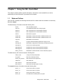
The bin directory will contain at least the following files:
iss.exe
ISS executable program
ssim.exe
PPC405GP/PPC440GP bus model program
iss405.icf
ISS configuration file for PPC405GP simulation
iss440.icf
ISS configuration file for PPC440GP simulation
issl.exe
ISS launcher program
init405.cmd
RISCWatch command file used to initialize PPC405 core
init440.cmd
RISCWatch command file used to initialize PPC440 core
rwppc.env
RISCWatch environment file
rwt.exe
Program that automatically updates the rwppc.env file
simchips.prd
RISCWatch configuration file describing simulated processors
simchips.pcf
Source for the simchips.pdr file
start405gp.bat
DOS BAT file used to start PPC405GP simulation
start440gp.bat
DOS BAT file used to start PPC440GP simulation
startup_iss.cmd
RISCWatch command file with common ISS setup options
The doc directory will contain at least the following files:
install_req.txt
Listing of the ISS prerequisites
iss_ug.pdf
ISS User’s Guide (this book)
license_end_user.txt
ISS end user license agreement
readme.txt
ISS readme file
quick_start.txt
Quick start information
quick_start.rtf
Quick start information (RTF Format)
The sample directory will contain at least the following files:
demo1_1.c
Source file for demo1 program
demo1_2.c
Source file for demo1 program
demo1_3.c
Source file for demo1 program
demo1_all
Executable file containing demo1 program
Using the ISS - Quick Start
1-1
1.1.1
demo2_1.c
Source file for demo2 program (serial port example)
demo2_2.c
Source file for demo2 program (serial port example)
demo2_405
Executable file for demo2 program compiled for PPC405GP
demo2_440
Executable file for demo2 program compiled for PPC440GP
make.opt
File containing options used by the make utility
makefile
Makefile used to build the sample programs
ppc.m4
Assembler include file with some PowerPC definitions
ppclib.s
Assembler source file
serial.h
Include file with the serial port definitions
Windows Quick Start Instructions
Since ISS, the PPC405GP/PPC440GP Bus Model program, and RISCWatch have a large set of
configuration options and startup sequence dependencies an ISS Launcher Program (issl.exe) is
provided to simply the process of starting an ISS session. Two Windows shortcuts (PPC405GP
Simulation and PPC440GP Simulation) are provided to run the ISS Launcher program. Clicking one
of these icons will start a PPC405GP or PPC440GP ISS session with commonly used configuration
options.
To start a PPC405GP or PPC440GP ISS session and run the supplied sample code, perform the
following steps:
• Start the 405GP or 440GP ISS session by clicking either Start–Programs–IBM PowerPC ISS –
PPC405GP Simulation or Start–Programs–IBM PowerPC ISS–PPC440GP Simulation.
• At the RISCWatch command line, execute the appropriate RISCWatch startup command file by
typing either exec init405.cmd or exec init440.cmd.
• From the RISCWatch command line, load the demo to be debugged using the command load file
demo1_all.
• Open the RISCWatch source code window to display and start executing the demo code using the
Source–Source pull down menu.
At this point breakpoints can be set by clicking in the source code window and the code can be
stepped or run by clicking the appropriate RISCWatch buttons. Please see the RISCWatch User's
Manual for information on how to debug programs using the RISCWatch debugger.
To end the session:
• Type quit on the RISCWatch command line or use the File–Quit pull down menu from the main
RISCWatch window.
1.1.2
The Sample Code
Three sample programs are provided with the ISS. The demo1_all program is very similar to the
demo program provided with RISCWatch. This program should run on any PowerPC processor and is
useful in learning to use the RISCWatch debugger. The demo2_405 and demo2_440 programs
contain a simple console application that is designed to run on the ISS in a default PPC405 or
PCC440 ISS session respectively and can be loaded using the load file command used in the
instructions above. The demo2 programs echos the serial data received from UART 0 input (from the
1-2
Instruction Set SImulator User’s Guide
PPC440GP/PPC405GP Bus Model program console) to the UART 0 output (to the
PPC405GP/PPC440GP Bus Model program console).
Notes regarding the demo2 sample code:
• A separate PPC405 and PPC440 version of this sample is needed since UART0 and UART1 are
located in a different memory mapped location in the 405GP and 440GP processor.
• demo2_440 relies on the TLB 3 mapping of UART0 to address 0xE0000200 and UART1 to
address 0xE0000300. This mapping is accomplished in the init440.cmd.
• A compiler option was used to generate eieio (PPC405) and mbar (PPC440) instructions as
needed in order to ensure the sequential ordering of storage accesses.
• Attempting to step through some of the input code that receives characters from UART 0 may
result in a RISCWatch timeout unless character input is available from UART 0. Character input is
provided to UART 0 by typing in the PPC405GP/PPC440GP Bus Model console window.
The sample programs can be rebuild using the GNU GCC compiler by executing gnumake command
in the sample directory. The supplied makefile can be used to rebuild the demo1_all, demo2_405
and demo2_440 programs. Please see the documentation provided with the GNU tools for more
information on compiling and building PowerPC programs.
1.1.3
Understanding an ISS Session
There are several programs and windows that are involved in an ISS session including the ISS
Launcher Program (issl.exe), the PPC405GP/PPC440GP Bus Model program (ssim.exe), the ISS
itself (iss.exe), and RISCWatch (rwppc.exe).
The ISS Launcher Program (issl.exe) handles the startup sequence dependencies of the other three
programs by starting them in the necessary order with the appropriate options. It also touches up the
RISCWatch path (RWPPC_DIR keyword) in the RISCWatch environment file (rwppc.env) by calling
the rwt.exe program prior to starting RISCWatch. The ISS Launcher Program terminates after it has
started the other three programs. The program properties of the ISS Launcher icon can be changed
to close on exit if the ISS Launcher Program windows does not close when the program terminates by
default.
The PPC405GP/PPC440GP Bus Model program (ssim.exe) contains models of the UART and UIC
peripherals that behave similar to the peripherals in the actual hardware. In the default simulation
environments, the output of UART 0 and 1 is displayed in the PPC405GP/PPC440GP Bus Model
program console window and the input to UART 0 comes from the same console window. This allows
a program that is running on the ISS to interact with a user as though the user is at terminal window
connected to the UART0. If the program running on the ISS does not need to interact with a user, the
PPC405GP/PPC440GP Bus Model program console window can be minimized during the program
execution.
The ISS program (iss.exe) contains the model of the processor core. This model fetches and
executes the PowerPC instructions under control of the RISCWatch debugger. The ISS routes all
core connect access (PLB, DCR, etc.) to the PPC40GP/PPC440GP Bus Model program. The ISS
window provides the initial status of the ISS and may be minimized during the ISS session.
The RISCWatch debugger program (rwppc.exe) is used to control the execution of the ISS in order
to facilitate the debugging of code on the ISS. Using RISCWatch a user can load, step through, and
run code on the ISS as well as examine and update memory locations and processor and modeled
peripheral registers. Even the contents of the processor's caches can be seen from a RISCWatch
Using the ISS - Quick Start
1-3
window. Debugging code using RISCWatch usually involves opening and using several RISCWatch
debug windows from the many pull down menus. Common debug windows often include a source
window, a memory window, a GPR (general purpose register) window and more.
Understanding how to operate the RISCWatch debugger is essential to an effective ISS session. The
Quick Start section of the RISCWatch user manual provides an overview of RISCWatch and should
be referred to by users unfamiliar with this program. Note that the steps listed above in the quick start
section should be used in place of the steps listed in the RISCWatch manual to start RISCWatch and
load the demo program.
1.1.4
Customizing an ISS Session
There are many ways to customize an ISS session. Advanced users that understand all of the
available options and startup sequence dependencies can create and use custom configuration and
command files to start all of the programs needed for their sessions. Users desiring simple changes in
the provided ISS sessions may find it more advantageous to update a few of the configuration and
command files that come with the ISS. This section describes the contents of these files and how
these files are used to start an ISS session.
The start405.bat and start440.bat command files start the issl.exe program with the command line
parameters used by the default PPC405 and PPC440 sessions respectively. Clicking the appropriate
icon installed in the start menu runs one of these command files.
The issl.exe command line parameters specify the processor type (PPC405 or PPC440), the ISS
startup configuration file, and the command line parameters to use when PPC405GP/PPC440GP Bus
Model program is started. The processor type is used by issl.exe to determine the processor model
parameter for ssim.exe (405gp or 440gp) and the RISCWatch –proc command line parameter
(sim_405gp or sim_440gp). The PPC405GP/PPC440GP Bus Model command line parameters are
passed to ssim.exe as supplied to issl.exe. The port and protocol specified using the -B option must
match the port and protocol used in the ISS configuration file (e.g. iss405.icf or iss440.icf) The ISS
startup configuration file name is specified to issl.exe using the -F option. This file name is passed to
the ISS using the @ command line option.
The RISCWatch environment file (rwppc.env) file can be changed if needed since only the
RWPPC_DIR line in it is updated by the rwt.exe program when the issl.exe program runs. The default
rwppc.env file specifies that the startup_iss.cmd file should run when RISCWatch starts. The
startup_iss.cmd file executes some RISCWatch commands helpful for using RISCWatch with the ISS
along with the included samples files.
The simchips.prd file contains definitions of the sim_405gp and sim_440gp chips. These chips are
subsets of the PPC405GP and PPC440GP processors.
The init405.cmd and init440.cmd files contain RISCWatch commands that initialize the PPC405 or
PPC440 processor cores to the point that RISCWatch can reliably load and run code.
The files mentioned in this section may be modified as needed to facilitate the use of a customized
ISS session. Complete descriptions of the available options for the ISS and PPC405GP/PPC440GP
Bus Model program are provided in the ISS User's Guide and should be consulted prior to attempting
any changes to these files.
1-4
Instruction Set SImulator User’s Guide
Chapter 2. Advanced Configuration
The Instruction Set Simulator (ISS) operates in two modes:
• Standalone
All accesses to memory are handled inside the simulator. No peripherals can be attached to the
simulator. Reading Device Control Registers (DCR) returns undefined values. Writing DCR does
not have any effect.
• Attached to a Bus Model (BM)
ISS connects to an external program (BM) using TCP/IP sockets. The external program can
simulate peripheral devices and memory. The BM responds to processor local bus (PLB) requests
and DCR requests from ISS. BM can also post normal priority and critical priority interrupts to ISS.
In both modes, the RISCWatch debugger can be used to control ISS. When not connected to a
debugger, ISS attempts to fetch an instruction from the reset vector address (0xFFFFFFFC). ISS
continues to execute instructions until the BM requests ISS termination, or the number of simulation
cycles specified in the startup option have elapsed.
2.1
Quick Start
Consult the Chapter 1, “Using the ISS - Quick Start,” on page 1-1 for additional quick start information
specific to each platform.
ISS program must start before the RISCWatch debugger starts. Issuing the iss –d command starts
ISS. This command, with no additional options, starts ISS in PPC405 mode with 512KB of local
memory at address 0xFFF80000 and 512KB of local memory at address 0x0; The –d option enables
the RISCWatch debugger to attach to ISS. To start ISS in PPC440 mode, use the iss –d –V 440
command.
After ISS and RISCWatch start, RISCWatch can issue normal debug commands. ISS does not
initially execute any instructions after being started with the –d option. ISS stops with the Instruction
Address Register (IAR) pointing to the reset vector.
RISCWatch should be configured for simulator target type. In the RISCWatch configuration file
(rwppc.env), set the TARGET_TYPE keyword to sim. The TARGET_NAME keyword should contain
an IP address for the machine where ISS is executing (a local address of 127.0.0.1 can be used if ISS
and RISCWatch are running on the same machine). Also in the RISCWatch configuration file the
PROC keyword should be set to the appropriate PowerPC processor core. For example, for PPC405
the PROC keyword should be set to PPC405B3, and for PPC440 the PROC keyword should be set to
PPC440A4. The RISCWatch README file lists all supported processor cores.
The following RISCWatch commands should also be issued in order to improve the performance: poll
status 1000, poll run 1000.
Advanced Configuration
2-1
2.2
Startup Options
ISS startup options can be specified in any order. If an option is used, its parameters must be entered
without any spaces. Following are some examples of ISS startup options:
• iss @iss440.icf -a 9999999
In this example, ISS reads the startup options from the iss440.icf file. The “@” option must the first
option. Any options following the “@” are ignored. No spaces are allowed between the “@” symbol
and file name.
• iss –d –M
In this example, ISS is started with 512KB of local memory configured at address 0x00000000
(default value) and 512KB of local memory at address 0xFFF80000 (default value). ISS waits for a
connection with the debugger. ISS simulates the PPC405 processor (default value). The –M option
specifies that deterministic multiply cycle count will be used in the simulation.
• iss –d –p 0x4002001 –r 5
In this example ISS is started with 512KB of local memory configured at address 0x00000000
(default value) and 512KB of local memory at address 0xFFF80000 (default value). ISS will wait for
connection from the debugger and will simulate the PPC440 processor with PVR register value set
to 0x4002001. The timer clock period will be equal to processor clock period.
• iss –l0x0@0x00100000:0,0xFFF00000@0x00100000:2 –d –B 127.0.0.1,10000,udp –V 440
In this example ISS is started with 1MB of local memory configured at address 0x00000000 and
1MB of local memory at address 0xFFF00000. ISS waits for a connection with the debugger and
attempts to connect to a BM at address 127.0.0.1, port number 10000, using the UDP protocol. ISS
simulates the PPC440 processor.
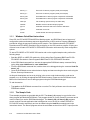
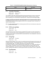
Table 2-1 shows the summary of all the startup options. Additional details on each option follow the
table.
Table 2-1. ISS Startup Options Summary
Option
Description
@filename
Read startup options from file.
–a value
Data cache size.
–B address,port,protocol
Bus model connection information.
–b addr@len[:era][,addr@len[:era]]
Back door memory.
–c value
Simulation time.
–d
Debugger connection.
–h
Help.
–i value
Instruction cache size.
–L
ISS execution priority.
–l addr@len,speed[:era][,addr@len:speed[:era]]
Local memory.
–M
Multiply cycle count.
–m value
ISS clock period.
2-2
Instruction Set SImulator User’s Guide
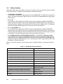
Table 2-1. ISS Startup Options Summary
Option
Description
–P value
Debugger port number.
–p value
Processor version register.
–R value
Processor PIR register value.
–r value
Timer clock period.
–s value
Delay startup.
–T era:e:u0u1u2u3
PPC440 reset TLB values.Ö
–V value
Processor version.
2.2.1
Startup file
If the startup file option is used it must be the first option. Any options following the startup file option
are ignored. No spaces are allowed between the “@” symbol and file name. The startup file contains
a list of keyword value pairs. The keyword should be separated from the value by the “=” symbol.
Only one keyword is allowed on each line of the startup file. An “#” characters specifies a comment.
Any text following a comment on the same line is ignored. If a keyword is not specified the default
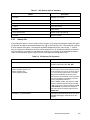
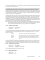
value for the equivalent option is used. Table 2-2 lists keywords recognized by ISS.
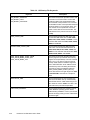
Table 2-2. ISS Startup File Keywords
Keyword
Description
PROCESSOR_VERSION
This keyword specifies type of processor being
simulated. Valid values are: 440, 405.
LOCAL_MEMX_START_ADDR
LOCAL_MEMX_START_EXT
LOCAL_MEMX_LEN
LOCAL_MEMX_SPEED
This series of keywords specifies ISS local
memory regions. Up to 8 local memory regions
can be specified (X is can be a number from 0
to 7). The memory regions must not overlap.
Valid values for address range from 0x0 to
0xFFFFFFE0. 36 bit address can be specified
only when simulating the PPC440 processor
by using the address extension
LOCAL_MEMX_START_EXT keyword. Valid
values for address extension range from 0x0
to 0xF. Local memory length ranges from 0x20
to 0xFFFFFFE0, and must be a multiple of
0x20. Valid values for speed range from 0 to
4294967295.
CONNECT_TO_DEBUGGER
This keyword specifies if ISS will connect the a
RISCWatch debugger. Valid values are no
and yes.
Advanced Configuration
2-3
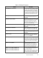
Table 2-2. ISS Startup File Keywords
Keyword
Description
BUS_MODEL_ADDRESS
BUS_MODEL_PORT
BUS_MODEL_PROTOCOL
This series of keywords specifies location and
connection for the bus model. A bus model
contains models of the peripherals that are
found outside of the processor core. The bus
model address value can be specified in dotted
decimal notation or as a machine name. The
port number can be specified as a numeric
value or name found in the services file. The
valid values for the protocol can be set to tcp
or udp.
DATA_CACHE_SIZE
This keyword specifies the data cache size.
For the 405 valid values are: 0, 1024, 2048,
4096, 8192, 16384, 32768, and 65536. For the
PPC440 valid values are: 8192, 16384, 32768,
65536, and 131072.
INSTRUCTION_CACHE_SIZE
This keyword specifies the data instruction
cache size. For the 405 valid values are: 0,
1024, 2048, 4096, 8192, 16384, 32768, and
65536. For the PPC440 valid values are: 8192,
16384, 32768, 65536, and 131072.
BACK_DOOR_MEMX_START_ADDR
BACK_DOOR_MEMX_START_EXT
BACK_DOOR_MEMX_LEN
This series of keywords specifies back door
memory regions. Up to 8 back door memory
regions can be specified (X is can be a number
from 0 to 7). The memory regions must not
overlap. Valid values for address range from
0x0 to 0xFFFFFFFE0. 36 bit address can be
specified only when simulating the PPC440
processor by using the address extension
BACK_DOOR_MEMX_START_EXT keyword. Valid values for length range from 0x20
to 0xFFFFFFE0, and must be a multiple of
0x20.
SIMULATION_TIME
This keyword allows the user to specify the
amount of simulation time (in nanoseconds)
that ISS will execute. Valid values range from
5 to maximum value 1.7e308. The value –1.0
(execute forever) can also be specified.
EXECUTION_PRIORIRY
This keyword specifies the execution priority
under Windows operating system. When
EXECUTION_PRIORITY is set to yes ISS will
execute as a high priority process. Valid values
are no and yes.
2-4
Instruction Set SImulator User’s Guide
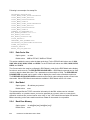
Table 2-2. ISS Startup File Keywords
Keyword
Description
DETERMINISTIC_405_MULTIPLY
This keyword specifies the handling of multiply
instructions when simulating PPC405 processor. When this keyword is set to yes multiply
instructions (mulhw, mulhwu, mulli, mullw) will
take 4 cycles to execute, otherwise execution
of multiply instructions is dependent on instruction and operands. Valid values are no and
yes.
CLOCK_PERIOD
This keyword specifies ISS clock period in
nanoseconds. Valid values range from 1 to
2147483647.
DEBUGGER_PORT_NUMBER
This keyword specifies the port number for the
debugger. Valid values range from 1 to 65535.
A range can be specified for this keyword
using following syntax low_port..high_port.
When range is specified ISS will try to find an
unused port in the specified range.
PROCESSOR_PVR_REGISTER
This keyword specifies the value of the PVR
register. Valid values range from 0x0 to
0xFFFFFFFF.
PROCESSOR_PIR_REGISTER
This keyword specifies the value of the PIR
register. Valid values range from 0x0 to 0xF.
This option is valid only for PPC440 processor
TIMER_CLK_PERIOD
This keyword specifies the timer clock period
in nanoseconds. Valid values range from 1 to
2147483647.
STARTUP_DELAY
This keyword specifies amount of time ISS
pauses execution during startup. Valid values
range from 0 to 2147483647.
RESET_440_TLB_ERA
This keyword specifies the Extended Real
Address (ERA) value in the shadow TLB upon
processor reset. The RESET_440_TLB_ERA
keyword is valid only when PPC440 processor
is simulated. Valid values range from 0x0 to
0xF.
RESET_440_TLB_ENDIAN
This keyword specifies the value of the
ENDIAN bit in shadow TLB upon processor
reset. The RESET_440_TLB_ENDIAN keywords valid only when PPC440 processor is
simulated. Valid values are 0x0 and 0x1.
RESET_440_TLB_USER_ATTRIBUTES_U0
RESET_440_TLB_USER_ATTRIBUTES_U1
RESET_440_TLB_USER_ATTRIBUTES_U2
RESET_440_TLB_USER_ATTRIBUTES_U3
This series of keywords specifies the values of
the user defined attributes in shadow TLB
upon processor reset. The
RESET_440_TLB_USER_ATTRIBUTES keywords are valid only when PPC440 processor
is simulated. Valid values are 0x0 and 0x1.
Advanced Configuration
2-5
Following is an example of a startup file:
PROCESSOR_VERSION=440
LOCAL_MEM0_START_ADDR=0x00000000
LOCAL_MEM0_START_EXT=0x0
LOCAL_MEM0_LEN=0x00080000
LOCAL_MEM0_SPEED=0
LOCAL_MEM1_START_ADDR=0xFFF80000
LOCAL_MEM1_START_EXT=0x1
LOCAL_MEM1_LEN=0x00080000
LOCAL_MEM1_SPEED=0
CONNECT_TO_DEBUGGER=yes
BUS_MODEL_ADDRESS=127.0.0.1
BUS_MODEL_PORT=10000
BUS_MODEL_PROTOCOL=udp
CLOCK_PERIOD=5
DEBUGGER_PORT_NUMBER=6470
PROCESSOR_PVR_REGISTER=0x40120000
TIMER_CLK_PERIOD=5
STARTUP_DELAY=0
RESET_440_TLB_ERA=0x1
2.2.2
Data Cache Size
Option syntax
–a value
Default value
8KB for PPC405, 32KB for PPC440
This option enables the user to alter the data cache size. For the PPC405 valid values are: 0, 1024,
2048, 4096, 8192, 16384, 32768, and 65536. For the PPC440 valid values are: 8192, 16384, 32768,
65536, and 131072.
The Correct cache size must be configured in RISCWatch in order for the RISCWatch cache display
functions to work correctly. The PRD ALTER DCACHE SIZE = n RISCWatch command can be used
in order to alter the data cache size. The n parameter must be multiple of 1024. The PRD DISPLAY
DCACHE SIZE command can be used in order to display the current value of the data cache size.
The PRD DISPLAY DCACHE LINES command can be used in order to display number of lines in the
data cache. Above RISCWatch commands are available in RISCWatch version 4.6 or later.
2.2.3
Bus Model
Option syntax
–B address,port,protocol
Default value
none
This options specifies the TCP/IP connection information for the BM. address can be in dotted
decimal notation, or a machine name. port can be specified as a numeric value or a name that is
defined in a services file. protocol can be set to “udp” or “tcp”. UDP should be used when ISS and the
BM are executing on the same machine and loss of data on the network is not possible.
2.2.4
2-6
Back Door Memory
Option syntax
–b addr@len[:era][,addr@len[:era]]
Default value
none
Instruction Set SImulator User’s Guide
This option enables the user to specify back door memory regions. Up to 8 back door memory
regions can be specified. The accesses to the back door memory region by the simulator will result in
PLB bus traffic with a special attribute specifying the back door memory. This option can be used in
order to identify BM memory regions that require special handling. The extended real address (ERA)
value can also be specified for the back door memory region. This value is only applicable when ISS
is configured to simulate the PPC440 processor. The length of the back door memory region must be
more than 32 and the sum of length and address must be less than 0xFFFFFFFF.
2.2.5
Simulation Time
Option syntax
–c value
Default value
–1.0
This option allows the user to specify amount of simulation time that ISS will execute. This option is
valid only when a debugger is not attached to ISS. Otherwise it will be ignored. The default value for
this option is –1.0, which specifies that ISS will execute forever. The number of cycles executed by
the simulator depends on the simulation time option and ISS clock period option. The following
formula can be used to calculate the number of cycles executed by ISS:
cycles = simulation time / simulator clock period
2.2.6
Debugger Connection
Option syntax
–d
Default value
none
This option allows the RISCWatch debugger to attach to ISS. After initializing the processor model
ISS will wait for a debugger connection before executing instructions. The simulator stops with the
IAR pointing to the reset vector. All registers will contain their reset values.
2.2.7
Help
Option syntax
–h
Default value
none
Displays help information for the options.
2.2.8
Instruction Cache Size
Option syntax
–i value
Default value
16K for PPC405, 32K for PPC440
This option enables the user to alter the instruction cache size. For the PPC405, valid values are 0,
1024, 2048, 4096, 8192, 16384, 32768, and 65536. For the PPC440 processor, valid values are:
8192, 16384, 32768, 65536, and 131072.
The Correct cache size must be configured in RISCWatch in order for the RISCWatch cache display
functions to work correctly. The PRD ALTER ICACHE SIZE = n RISCWatch command can be used
in order to alter the data cache size. The n parameter must be multiple of 1024. The PRD DISPLAY
ICACHE SIZE command can be used in order to display the current value of the data cache size. The
Advanced Configuration
2-7
PRD DISPLAY ICACHE LINES command can be used in order to display number of lines in the data
cache. Above RISCWatch commands are available in RISCWatch version 4.6 or later.
2.2.9
ISS Priority
Option syntax
–L
Default value
none
Windows only. By default, ISS executes on Windows as a normal priority thread. When–L is
specified, ISS executes as a high priority thread on Windows operating system. When executing at
high priority the response times of the interactive Windows applications might slow.
2.2.10 Local Memory
Option syntax
–l addr@len:speed[:era][,addr@len:speed[:era]]
Default value
0x0@0x80000:0,0xFFF80000@0x80000:0 for 405
0x0@0x80000:0.0xFFF80000@0x80000:0:1 for 440
This option allows the user to specify local memory. Local memory is available to software running on
ISS at the range defined by addr and len. len must be a multiple of 32, and the sum of len and addr
must be less than 0xFFFFFFFF. Accesses to local memory do not result in PLB transactions to the
BM. Up to 8 local memory regions can be specified. Specifying –l none turns off local memory. speed
represents the number of cycles required to access local memory. To determine the number of cycles
required to access a particular number of bytes, use the following formula:
ceil(number of bytes / 8) × speed
For example, if speed is set to 2 and ISS requests a 32-byte transfer, the transaction requires 8
cycles. The extended real address (era) value for local memory region applies only when ISS is
configured to simulate the PPC440 processor.
2.2.11 Multiply Cycle Count
Option syntax
–M
Default value
none
PPC405 processor only. When –M is specified, ISS simulates deterministic multiply. This affects the
simulated cycle count for the mulhw, mulhwu, mulli, and mullw instructions. When –M is specified,
these instructions execute in four cycles. Otherwise, multiply instruction cycle counts depend on the
type of instruction and size of the instruction operands.
2.2.12 ISS Clock Period
Option syntax
–m value
Default value
5
This option specifies ISS clock period. The value is expressed in nanoseconds (ns). The default value
of 5ns results in a 200MHz simulated clock speed.
2-8
Instruction Set SImulator User’s Guide
2.2.13 Debugger Port Number
Option syntax
–P value[..upper_limit]
Default value
6470
This option allows ISS to connect to the RISCWatch debugger using an alternative port number.
When multiple copies of ISS run on one machine, each instance of ISS must use a unique port
number for the RISCWatch debugger connection. In the RISCWatch configuration file (rwppc.env),
the keyword SIM_SERVICE specifies the port name used to connect to the simulator. The specified
name must be found in the TCP/IP services file. In the services file, set the RISCWatch debugger
connection protocol to tcp, for example: sim1 6471/tcp. RISCWatch port number can also be
specified on the command when invoking RISCWatch program. The RISCWatch command line
argument “-tportvalue” allows for specification of the port number.
If the upper_limit value is specified ISS will attempt to search for unused port number starting with
value and stopping when either a unused port number is located or upper_limit value is reached.
2.2.14 Processor Version Register
Option syntax
–p value
Default value
0x40110000 for PPC405,
0x40020000 for PPC440
This option specifies a Processor Version Register (PVR) value. This register can not be modified
after ISS starts.
2.2.15 Processor PIR Register
Option syntax
–R value
Default value
0
This option specifies a Processor Identification Register (PIR) value. This register can not be modified
after the ISS starts.
2.2.16 Timer Clock Period
Option syntax
–r value
Default value
5
This option specifies the timer clock period in nanoseconds (ns). For example, if ISS clock period is
set to 5 and the timer clock period is set to 10, the Time Base Lower (TBL) register is updated every
other cycle. The timer clock period must be equal to the clock period or be a multiple of the clock
period.
2.2.17 Delay Startup
Option syntax
–s value
Default value
0
This option delays ISS execution (during startup) for value seconds. –s can delay ISS execution to
enable BM initialization.
Advanced Configuration
2-9
2.2.18 PPC440 Reset TLB Values
Option syntax
–T era:e:u0u1u2u3
Default value
0x1:0x0:0x0
PPC440 processor only. When the PPC440 processor is reset, this option defines the following fields:
extended real address (era), endian (e), user-defined storage attribute 0 (u0), user-defined storage
attribute 1 (u1), user-defined storage attribute 2 (u2) and user-defined storage attribute 3 (u3). era
must be less than 0x10. e must be 0 or 1. u0u1u2u3 must be less than 0x10, with each bit
representing a single user-defined storage attribute value. The least significant four bits for the userdefined storage attribute value are used for assignment. The least significant value is assigned to u3.
2.2.19 Processor Version
Option syntax
–V value
Default value
405
This option alters the type of processor being simulated by ISS. Valid values for this option are 405
and 440.
2.3
PPC405GP/PPC440GP Bus Model Program
The PPC405GP/PPC440GP bus model program is not included in all installations. Consult the
Chapter 1, “Using the ISS - Quick Start,” on page 1-1 to verify if the PPC405GP/PPC440GP bus
model program is included in as part of a particular installation.
The PPC405GP/PPC440GP bus model program is contained in the ssim executable. This program
contains models of the 16550 Universal Asynchronous Receiver Transmitter (UART) and Universal
Interrupt Controller (UIC) found in the PPC405GP and PPC440GP processors.
Command line arguments are used to configure the various features of PPC405GP/PPC440GP bus
model program. The PPC405GP/PPC440GP bus model program startup options can be specified in
any order. If an option is used, its parameters must be entered without any spaces.
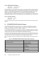
Table 2-3 shows the summary of all the startup options. Additional details on each option follow the
table.
Table 2-3. PPC405GP/PPC440GP Bus Model Startup Options Summary
Option
Description
–B address,port,protocol
Connection information.
–d
DCR scratch-pad mode.
–D
Debug flags.
–e
Error messages.
–h
Help.
–p value
Processor model.
–u
UART options.
2-10
Instruction Set SImulator User’s Guide
Table 2-3. PPC405GP/PPC440GP Bus Model Startup Options Summary
Option
–w
2.3.1
Description
Warning messages.
Connection Information
Option syntax
–B port,protocol
Default value
11000,udp
The connection information argument specifies the socket port and protocol used to communicate
with ISS. This argument is specified following the –B switch and is made up of a port number or
name, followed by a coma, followed by the desired protocol. Valid protocols include tcp and udp.
In general, the UDP protocol should be used if this program will run on the same machine as ISS or
on separate machines connected via a small reliable network. The TCP protocol should be used if the
PPC405GP/PPC440GP bus model program and ISS will run on separate machine connected via a
large or unreliable network.
Note: The PPC405GP/PPC440GP bus model program and ISS must use the same port and protocol
in order to communicate.
2.3.2
DCR Scratch-pad Mode
Option syntax
–d
Default value
none
The DCR scratch-pad mode treats otherwise unmodeled DCR registers as scratch-pad registers. In
this mode, the value written to each unmodeled DCR is returned when it is read. If this mode is not
enabled, the value written to unmodeled DCR’s is discarded and the value 0xdeadbeef is returned on
unmodeled DCR reads.
2.3.3
Debug Flags
Option syntax
–D number
Default value
none
Additional debug messages can be turned on by specifying the debug flag argument following the –D
command line switch. The debug flag argument is a 32 bit hex number resulting from the logical OR
of individual debug flags. The available debug flags can be displayed by starting
PPC405GP/PPC440GP bus model program with the –D? argument. The available debug flags are
likely to change in subsequent versions of PPC405GP/PPC440GP bus model program and not
intended for general use. They may be useful as a debug aid for both the software running on ISS
and the PPC405GP/PPC440GP bus model program itself but are provided as-is with no guarantees.
2.3.4
Error Messages
Option syntax
–e
Default value
none
Advanced Configuration
2-11
The PPC405GP/PPC440GP bus model program can print error messages to indicate that a possible
severe problem exists in the code running on ISS. Typical errors include accessing unmodeled PLB
address and multi-byte accesses to single byte devices.
2.3.5
Processor model
Option syntax
–p value
Default value
405gp
The processor model argument specifies that the configuration (number, memory map, etc.) of the
modeled peripheral cores should match those of the indicated processor. This argument is specified
following the –p switch. Valid values include 405gp and 440gp.
2.3.6
UART Options
The UART models supplied in PPC405GP/PPC440GP bus model program have several configurable
modes that can be specified in arguments following the –u command line switch. Each UART mode
argument must follow a –u switch and must be in the form xmo, where x is the UART number, m is
the mode, and o is the mode option.
Both the PPC405GP and PPC440GP have two UART models, identified as UART number 0 and 1.
Each UART has three configurable modes: speed (s), console (c), and frequency (f). The options for
each mode are described below.
2.3.6.1
UART Speed Option
Option syntax
–u(0|1)s(f|s)
Default value
-u0sf -u1ss
The speed mode of the UART models adjusts the amount of simulated time delay associated with
receiving and sending characters to and from the UART. The supported speed mode options include
slow (s), medium (m), and fast (f).
In all of the speed modes, when the UART is configured to receive input from the console (see below)
and the UART is not currently receiving a character, the UART polls the console once per bit time to
see if a character is available from the console. The bit time can be changed by configuring the UART
frequency (see below) or changing the value of the UART's baud rate divisor registers.
In slow speed mode, the UART realistically simulates the delays associated with sending and
receiving serial characters, taking the serial clock speed, current baud rate divisor, and modem line
control register values into account. In this mode (as in the real hardware), characters take a full
character time to transfer in and out of the serial port of the UART. Characters also take a full bit time
to transfer from the FIFO into an empty transmitter.
Slow speed mode is useful when running or debugging code that needs accurate time modeling in
order to work correctly. For instance, code that determines the processor speed by putting the UART
in loopback mode and timing the transmission and reception of characters works correctly in slow
speed mode. Slow speed mode is not desirable when the UART will be used for live user input since
PPC405GP/PPC440GP bus model program and ISS together run approximately 1000 times slower
than hardware speeds.
In fast speed mode, the UART does not simulate the delays associated with sending and receiving
serial characters. Characters written to the FIFO are sent to the transmitter and subsequently written
2-12
Instruction Set SImulator User’s Guide
to the console (if configured) in zero simulation time. Likewise, characters received from the console
are written to the FIFO in zero time.
Fast speed mode is useful when the UART will be used for live user input since the responsiveness of
the system depends only on the time required for the simulated code in ISS to get the characters to
and from the UART. Fast speed mode obviously will not work with code that depends on the true
timings of real hardware. In addition, since characters can be received from the console and put into
the UART FIFO with no simulated delay and the code running on ISS runs approximately 1000 times
slower than the actual hardware, FIFO overruns can easily occur in this mode. This can be avoided
by typing very slowly on the console window.
In medium speed mode, the UART simulates all of the delays simulated in slow mode but waits only a
bit time instead of a full character time to transmit and receive characters. This mode is useful when
the UART will be used for live user input but the code running on ISS has some hardware timing
dependencies. The character transfer speed in UART medium speed mode can be adjusted by using
the UART frequency option. Increasing the UART frequency increases the character transfer speed.
Decreasing the UART frequency decreases the character transfer speed.
Note: When writing to the UART transmitter holding register from RISCWatch, the UART model must
run before the character will appear on the console output, even in fast speed mode. This can
be accomplished by assembly stepping or running instructions from RISCWatch.
2.3.6.2
UART Console Option
Option syntax
–u(0|1)c(0|1|2|3)
Default value
-u0c3 -u1c0
The console mode specifies whether the serial input to and serial output from the UART model should
be directed from and/or to the PPC405GP/PPC440GP bus model program console. The console
options are as follows:
0 (none)
UART never receives input, UART output is discarded.
1 (input)
UART receives input from the console, UART output is discarded.
2 (output)
UART never receives input, UART output goes to the console.
3 (both)
UART receives input from the console, UART output goes to the
console.
Note that PPC405GP/PPC440GP bus model program runs slower if either mode 1 (input) or mode 3
(both) is specified since the UART model will periodically poll the console for serial input in theses
modes. Also note that only one UART is allowed to be configured to receive input from the console.
2.3.6.3
UART Frequency Option
Option syntax
–u(0|1)fnumber
Default value
-u0f11059200 -u1f11059200
The simulated speed of the UART serial clock in Hertz.
2.3.7
Warning Messages
Option syntax
–w
Default value
none
Advanced Configuration
2-13
The PPC405GP/PPC440GP bus model program can print warning messages to indicate that a
possible problem exists in the code running on ISS. Typical warnings include accessing unmodeled
DCR’s, writing to read-only registers, reading empty FIFO’s, and setting reserved bits.
2.4
Sample Bus Model Program
The sample Bus Model program is not included in all installations. Consult the Chapter 1, “Using the
ISS - Quick Start,” on page 1-1 to verify if the sample Bus Model program is included in as part of a
particular installation.
ISS includes a sample Bus Model (BM) program, which can be used to monitor the PLB transactions
that are not handled by local ISS memory. The sample BM program can also be set up in order to
support an additional 8 memory regions. DCR and reset transactions can be monitored with the
sample BM. The sample bus model can also be used in order to display the communication protocol
information and traffic between the bus model and ISS. The sample BM program is contained in the
dummybm executable. The sample BM program must be started before ISS is started.
2.5
Cycle Accuracy
When ISS is configured to simulate the PPC405 processor, ISS operates in cycle approximate mode.
In this mode, if the program running on ISS does not perform any external memory accesses
(program is executing out of instruction cache, and it is using the data cache for data storage), its
execution is nearly 100% cycle accurate. When the program running on ISS performs external
memory accesses, the execution of this program is not identical to execution of the same program on
real hardware. In cycle approximate mode, all architected processor resources are modeled, except
as specified in “ISS Functional Limitations.”
When ISS is configured to simulate the PPC440 processor, ISS operates in architectural mode. In
architectural mode, all architected processor resources are modeled, except as specified in “ISS
Functional Limitations.” The number of cycles required to execute a program in architectural mode is
not the same as required to execute the same program on real hardware.
2.6
ISS Functional Limitations
PPC405 mode has the following functional limitations:
• Misaligned little endian storage references cause alignment exceptions.
• Debug wait mode (DWM) is not supported in ISS.
• Setting reserved bits in SPRs can have a different effect than in real hardware.
• The stwcx instruction does not issue a request to the storage if the reservation bit is off. On a real
PPC405 processor, the request is issued and then aborted on the next cycle.
• Execution of instructions having invalid instruction forms does not result in the same behavior as
executing such instructions on real hardware.
• When ISS is initialized, DBSR[MRR] shows system reset rather than the actual reset type.
2-14
Instruction Set SImulator User’s Guide
• The icbt instruction, issued against a non-executable region, is treated as a no-op. On a real
PPC405 processor, icbt issued against non-executable region brings the data into the instruction
cache. When execution of this data is attempted, the ISI exception is generated.
Functional limitations in PPC440 mode:
• Misaligned little endian storage references cause alignment exceptions.
• Debug wait mode (DWM) is not supported in ISS.
• Setting reserved bits in SPRs may have a different effects than in real hardware.
• Execution of instructions having invalid instruction forms does not result in the same behavior as
executing such instructions on real hardware.
• When ISS is initialized, DBSR[MRR] shows system reset rather than the actual reset type.
2.7
Cycle Stepping
The RISCWatch sim command enables RISCWatch to send commands to ISS. Parameters specified
after the sim keyword are passed to ISS. Currently, only the cs count [nc] parameter is allowed. The
cs (cycle step) command causes ISS to execute for count cycles. The optional nc keyword can be
used with the cs command. When nc is specified, cs does not modify any ISS registers while
performing the cycle step. This enables stepping over code that reads and writes the debug registers.
When nc keyword is specified, ISS might not stop on a breakpoint.
When cycle stepping ISS, the RISCWatch socket time-out value should be set to a sufficiently large
value to allow the cycle step to complete before RISCWatch times out the command. This is done by
executing the socket timeout command.
While cycle stepping, the simulator can get into states that do not allow (or ignore) attempts to change
ISS facilities from RISCWatch. This is caused by the possibility of instruction being partially executed
in the simulated processor pipeline. Assembly stepping or running or stopping returns ISS to a known
state, from which all RISCWatch actions are valid. When assembly stepping, or running or stopping,
the processor pipeline is flushed before ISS stops. This is similar to actions taken by real hardware
when assembly stepping or running or stopping.
2.8
Tracing Instructions and Data
There are four RISCWatch commands that control tracing of instruction and data accesses made by
the program running on ISS.
• sim traceopen [filename [instruction_format [data_format]]] command opens a file that will be
used to save trace data. If filename is not specified default file name (isstrace.out) will be used to
write trace data. If optional instruction_format and data_format strings are not specified most
recently specified format strings will be used. If the format strings where never specified the
default instruction format string "I_0x%8.8x_0x%8.8x", and default data format string
"D_0x%8.8x_0x%8.8x_%-9s_%2d" will be used. In order to specify the data_format string
filename and instruction_format string must also be specified since the parameters are positional.
The underscore ('_') character in the format string is replaced by space (' ') character by the ISS.
The underscore ('_') character is required since the RISCWatch sim command interprets space (' ')
character as a delimiter. The new-line ('\n') character is appended to the end of the
Advanced Configuration
2-15
instruction_format and data_format strings. No quotes should be specified when entering this
command with RISCWatch. The instruction trace is formatted using following C language function
sprintf(buffer, instruction_format, instruction_address,
instruction_value)
The data trace is formatted using following C language function
sprintf(buffer, data_format, effective_address, data_to_be_written,
access_type, access_size)
Although the instruction_format and data_format strings can be altered the order and the type of
information passed to the formatting functions can not be altered. The instruction_address,
instruction, value, effective_address, data_to_be_written and access_size parameters are passed
to formatting functions as integers, The access_type parameter is passed to formatting function as
a string. Following is an example of the sim traceopen command:
sim traceopen mytrace.out I_address=0x%8.8x_instruction_value=0x%8.8x
D_address=0x%8.8x_value=0x%8.8x_type=%-9s_size=%2d
• sim traceclose command closes current trace file.
• sim tracestart [instruction_format [data_format]] command starts the trace. If the trace file was
not open the trace output is directed to the console screen. The optional instruction_format and
data_format strings follow the same rules as described in the sim traceopen command.
• sim tracestop command stops the trace.
2.9
Optimizing ISS Performance
To optimize ISS performance, local memory speed should be set to 0 cycles. For PPC 405 processor
simulation, the Storage Guarded Register (SGR) should be set to 0 to minimize delays caused by
guarded accesses. For the PPC440 processor, the TLB should have the G storage attribute cleared.
The time clock period option and ISS clock period options should have the same value. The
RISCWatch status polling and run polling should be set to value equal to or greater then 1000. This
can be done by issuing following RISCWatch commands: poll status 100000, poll run 1000.
2.10 ISS Requirements
ISS is supported under 32-bit Windows platforms. ISS memory requirements depend on the amount
of local memory configured for ISS. For example, if ISS is configured to support 16MB of local
memory, the machine running ISS should have at least that amount of memory available in addition to
the amount required by the operating system. If no local memory is configured, ISS requires 1MB of
memory in addition to the amount required by the operating system.
When connected to a debugger, ISS requires RISCWatch version 4.7 or later.
ISS performance is directly related to the speed of the machine running ISS. A machine with a
400Mhz processor will execute ISS almost twice as fast as a comparable 200Mhz machine.
2-16
Instruction Set SImulator User’s Guide
2.Advanced Configuration
This page intentionally lest blank
Advanced Configuration
2-17
2.
This page intentionally lest blank
2-18
Instruction Set SImulator User’s Guide
2.Advanced Configuration
This page intentionally lest blank
Advanced Configuration
2-19
2.
This page intentionally lest blank
2-20
Instruction Set SImulator User’s Guide