1
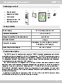
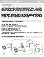
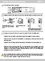
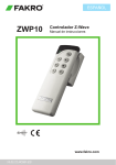
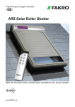
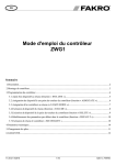
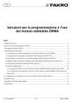
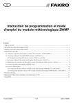
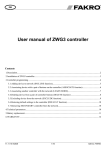
ENGLISH ZWP1 0 Z-Wave Controller User Manual www.fakro.com 14.03.12 NC851-GB Contents ZWP 1 0 Dear Sir/Madam! Thank you for purchasing product from FAKRO Company. We do hope that it will meet your expectations. To provide appropriate functioning of the product, please read this User Manual. Contents Information about the product...........................................................................................3 Packaging content..................................................................................................3 Technical data.........................................................................................................3 Product description.................................................................................................3 Control modes........................................................................................................4 General information about the Z-Wave system ................................................................5 General information................................................................................................5 Basic functions of the Z-Wave system....................................................................5 Sample scheme of the Z-Wave network.................................................................5 Preparing controller for programming ..............................................................................6 Controller programming – quick configuration ...............................................................7 Adding device to the controller and buttons of movement......................................7 Controller programming – basic functions ......................................................................8 Adding device to the controller – INCLUDE............................................................8 Adding device only to buttons of movement - ASSOCIATE...................................8 Adding another controller to the Z-Wave network - LEARN MODE.......................9 Removing device from the controller - EXCLUDE................................................1 0 Restoring the controller to factory settings - DEFAULT........................................1 0 Removing one device from buttons of movement - DELETE...............................11 Removing group of devices from given buttons of movement - DELETE.............11 Controller programming – additional functions .............................................................1 2 Adding remote device to the Z-Wave network - ASSIGN A ROUTE.....................1 2 Associating Z-Wave devices - ASSOCIATE DEVICE...........................................1 3 Copying group of devices - COPY GROUP..........................................................1 3 Range of Z-Wave devices ................................................................................................1 4 Range of Z-Wave devices depending on the surrounding environment...............1 4 Declaration of Conformity / Warranty..............................................................................1 6 2 ZWP 1 0 Information about the product Packaging content 1 2 3 4 5 Remote control 1 Magnetic wall holder 2 4 3 5 ITALIANO ZWP1 0 Radiocomando Z-Wave Istruzione d'uso User manual Batteries 2 x AAA 1 ,5V Mounting screws www.fakro.com 13.06.03 NC851-IT Technical Data Power supply Operation temperature Range of operation in the open space 3V DC, Battery 2xAAA 1 ,5 V (+5°C) to (40°C) up to 40 [m] Wireless Protocol Operation frequency Sizes (length/width/height) 868,4[Mhz] (EU); 921 ,42[MHz] (AS/NZ); 908,4[MHz] (US/Canada) 1 57 / 38 / 1 9 [mm] Product description The ZWP1 0 controller enables radio control of FAKRO electrical accessories and of other manufacturers that are compatible with the Z-Wave system. The ZWP1 0 controller operates up to 1 0 devices, separately on 5 channels (2 devices for 1 channel). It also allows for creation of 1 0 independent groups. Each group can include several devices operated simultaneously. Controller's memory can contain up to 231 devices. The ZWP1 0 controller is equipped with a two-way Z-Wave radio communication module exploiting radio wave frequency (frequency depending on the country for which the product is intended). It can be used as the basic controller – PRIMARY as well as an additional – SECONDARY. PRIMARY controller allows for integration of many devices into one radio network while SECONDARY is used as an additional controller in already existing network (see LEARN MODE function). In addition to Basic Mode of operation: OPEN, STOP, CLOSE, the ZWP1 0 controller offers Multilevel Mode allowing for e.g. smooth dimming of the light. 3 ZWP 1 0 Information about the Z-Wave 1 LEDs signalling active channel: 1 - channel 1 2 - channel 2 3 - channel 3 4 - channel 4 1 ,2,3,4 - channel 5 1 1 2 3 4 2 2 Button of SELECT channel choice 3 Buttons of MOVEMENT – operate single device or group of devices OPEN, STOP, CLOSE 4 Groups of controlled devices: group 1 ,2 – channel 1 group 3,4 – channel 2 group 5,6 – channel 3 group 7,8 – channel 4 group 9,1 0 – channel 5 5 Programming button IN/EX under back cover of the remote control 3 4 Control modes Basic – press button of movement or within 0.5 sec. in order to cause the device to move and press in order to stop the device. Multilevel – press button or and hold until the device reaches desired position and then release the button. 4 5 ZWP 1 0 Information about the Z-Wave Operation of FAKRO products is based on radio communication protocol Z-Wave. To enable the controller to operate FAKRO Z-Wave electrical accessories, it is necessary to configure them appropriately into one Z-Wave radio network. For this purpose there are used appropriate commands performed on the controller. Each network has its address (HomeID) and each device in the network has its number (NodeID). All devices in the Z-Wave network are divided into operating devices – controllers and devices controlled (e.g. servo-motors). Single controlled device can operate only within one network (single HomeID) and one network can include only one basic PRIMARY controller (overriding). In order to add second controller, it must be set as SECONDARY (subordinate). When configuring devices to operation in the network, address (HomeID) is assign to them and Node ID appropriate in order (fig. 1 ). Basic functions of the Z-Wave system Include - adding device to the network Associate - adding device to buttons of movement (group) Delete - removing device from buttons of movement (group) Exclude - removing device from the network Learn Mode - adding another controller Default - restoring controller to factory settings To simplify configuration, some of above procedures were joined what will be explained in the chapter concerning programming. Sample scheme of the Z-Wave network Z-Wave I Secondary ZWG3 H om eID A A A Exclude Default Primary Z-Wave II ZWP10 ARZ Z-Wave Delete Include NodeID 000 Fig.1 NodeID 003 ARZ Z-Wave H om eID AAA Learn Mode Assciate NodeID 002 ZWG3 NodeID 001 Primary 5 Preparing controller for programming ZWP 1 0 1 Put batteries in the controller 2 Attach holder to the remote control in a location that is convenient for you. Screw holder firmly to the wall with the use of anchor pins. 3 Put the washer on the holder. Check whether the remote control is firmly located in magnetic washer. Prepare device which is to be operated (see Product User Manual) Make sure that the device is appropriately installed and plugged in to power supply. Make sure that you have physical access to programming button and device manual operating button. Make sure that the device operates appropriately by pressing manual operating button. Make sure that the network status LED on the device which is to be added to controller lights up. If the network status LED does not emit light it means that the device is not plugged in to power supply (manual operation does not work) or it has already been assigned to the same or other controller. Note! In devices powered by photovoltaic panel (AMZ Z-Wave Solar awning blind, ARZ ZWave Solar roller shutter) the network status LED should light up for 5 sec. after pressing P button what means readiness to assign device to the network. ! 6 ZWP 1 0 Controller programming – quick configuration Adding device to the controller and buttons of movement If device has not been purchased with the controller in a set, it should be programmed. If the network is configured again, it is necessary to reset the controller to factory settings (DEFAULT function) and then follow below presented steps in appropriate time intervals. 1 Choose one of 5 channels on which the device is to be assigned by pressing SELECT button. 2 Press IN/EX button on the back of the controller. If LEDs 1 and 4 light up, then press one of movement buttons of a given group until LEDs change for 1 ,2,3. 1 2 3 4 IN/EX x1 4 1 x1 3 Within 1 0 sec. press P button on the device until the network status LED is off (see device programming manual). - Controller signals device correct adding by lighting of LEDs 2,3,4 - Controller signals device incorrect adding by blinking of LEDs 1 ,2,3 and the procedure should be performed again from point 2. 1 2 3 x1 2 3 4 1 2 3 After the above steps to ensure proper operation of the device, wait 1 0sec. Now controller is ready to operate. Note! If one omits step 2, that is pressing button of movement, the device will be added only to the network (see INCLUDE function). Then, to be able to operate the device, it is necessary to add it to buttons of movement with the use of ASSOCIATE function. In order to add another device to the same or other group, it is necessary to perform above procedure again. ! 7 ZWP 1 0 Controller programming – basic functions Adding device to the controller - INCLUDE Adding device only to the controller's memory is required if the user wants device to be in the Z-Wave network and operated e.g. only by subordinate controller (SECONDARY). 1 Press once IN/EX button on the controller. LEDs 1 and 4 will light up. 2 Within 1 0 sec. press P button on the device until the network status LED is off (see device programming manual). - Controller signals device correct adding by lighting of LEDs 2 and 3. - Controller signals device incorrect adding by blinking of LEDs 1 and 4 and the procedure should be performed again. IN/EX x1 4 1 x1 4 2 3 1 Adding device only to buttons of movement - ASSOCIATE If device has already been assigned to the controller for buttons of movement (group) it can be added to another group with the use of ASSOCIATE function. 1 Choose one of 5 channels on which the device is to be assigned. 2 Within 1 ,5 sec. press once IN/EX button and once button of movement of a given group to which device is to be added. LEDs 1 ,2,3 will light up. 1 2 3 4 IN/EX t<1s x1 x1 3 Within 1 0 sec. press P button on the device (see device programming manual). 8 - Controller signals correct adding to group by lighting of LEDs 2,3,4 - Controller signals incorrect adding by blinking of LEDs 1 ,2,3 and the procedure should be performed again from point 2. 1 x1 2 3 4 1 2 3 2 3 ZWP 1 0 Controller programming – basic functions Adding another controller to the Z-Wave network – LEARN MODE Function is used for copying information about devices from basic controller (PRIMARY) to additional and making it a SECONDARY controller. After performing LEARN MODE on the controller, it is also necessary to assign device to buttons of movement with the use of ASSOCIATE function. It is better to perform LEARN MODE function after adding all devices to basic controller or after modification of the network. IN/EX 1 Press once IN/EX button on basic remote control. LEDs 1 and 4 will light up. 2 Within 1 0 sec. press three times IN/EX button on additional remote control until lighting of LEDs 1 and 3. Within 1 0 sec. on basic remote control LEDs 2 and 3 will light up and on additional 2 and 4 will light up. If the sequence does not occur, perform the procedure from the beginning. ! x1 4 1 IN/EX x3 3 1 PRIMARY SECONDARY 2 3 2 4 Note! With the use of an additional controller – SECONDARY it is not possible to add device to the network (INCLUDE) and remove device from the network (EXCLUDE). However, it is possible to perform ASSOCIATE and DELETE functions. PRIMARY and SECONDARY function of the controller can be performed by controllers from different companies complying with Z-Wave protocol. To set the SECONDARY controller as PRIMARY again, perform the DEFAULT function. 9 ZWP 1 0 Controller programming – basic functions Removing device from the controller - EXCLUDE If the user wants to completely remove device from the Z-Wave network (reset HomeID) e.g. in order to assign to another controller, below presented procedure must be performed. But one should bear in mind that this procedure will remove device from buttons of movement and controller's memory. 1 Press twice IN/EX button within 1 sec. LED's 2 and 3 will light up. 2 Within 1 0 sec. press P button on the device and hold until the network status LED lights up (see device programming manual). x2 IN/EX t<1s 2 3 x1 - Controller signals device correct removing from the network and group by lighting of LEDs 1 and 4. - Controller signals incorrect removing by blinking of LEDs 2 and 3 and the procedure should be performed again from point 1 . 4 1 2 3 Note! With the use of EXCLUDE function it is also possible to remove (reset) devices assigned to other networks. ! Restoring controller to factory settings - DEFAULT Resetting the controller will cause removing of all devices from its memory and the change of unique HomeID network address for a new one. Removing devices from the controller will not cause reset of devices themselves. If the user wants to add them once again to the Z-Wave network (controller's memory) it is necessary to perform EXCLUDE procedure on devices and assign them again. 1 IN/EX x2 Within 1 sec. press twice IN/EX button and once SELECT button until LEDs 2,3-1 ,4-2,3 blink. - If a given sequence of LEDs does not occur it is necessary to perform procedure again. t<1s DEFAULT function will set the SECONDARY controler again as the PRIMARY controller. 1 10 2 3 4 x1 ZWP 1 0 Controller programming – basic functions Removing one device from buttons of movement - DELETE Function is used for removing particular device from buttons of movement without removing it from the network. 1 Choose channel on the controller from which the device is to be removed. 2 Within 1 .5 sec. press twice IN/EX button and once one of buttons of movement of a given group. LEDs 1 ,2,3 will light up. 1 2 3 4 t<1s x2 IN/EX x1 3 Within 1 0 sec. press P button on the device and hold until LEDs on the controller change into 1 ,2,3. - Controller signals error by blinking of LEDs 2,3,4 and procedure must be performed again. 2 3 4 x1 2 3 1 2 3 4 Removing group of devices from buttons of movement - DELETE This function is used for removing all devices from buttons of movement of a given group without removing them from the network. Choose channel on the controller from which group of devices is to be removed. 1 2 Within 1 ,5 sec. press twice IN/EX button and once any button of movement of a given group until LEDs 1 ,2,3 light up. 1 x2 2 3 4 t<1s IN/EX x1 3 Within 1 0 sec. confirm removing devices by pressing STOP button of a given group. - LEDs 1 ,2,3 will light up on the controller. Otherwise procedure must be performed again. 2 3 4 x1 1 2 3 11 ZWP 1 0 Controller programming – additional functions Adding remote device to the Z-Wave network - ASSIGN A ROUTE Function allows for adding already installed Z-Wave device to SECONDARY controller, permanently installed (e.g. ZWMP or ZWMA weather module) via PRIMARY controller (transferring Node INFO). Such situation occurs when device (SECONDARY controller and controlled device) are not in direct contact with each other or time to perform ASSOCIATE procedure is too short. x1 x1 t<1s IN/EX 1 Within 1 sec. press IN/EX button and once SELECT button on PRIMARY controller. LEDs 1 and 2 will light up. 2 Within 1 0 sec. press P button on the device until LEDs on the controller change into 3 and 4. 3 On the target controller – SECONDARY (e.g. ZWMA module) within 60 sec. choose channel and perform ASSOCIATE function – within 1 sec. press IN/EX button and button of movement of a given group until LED's 1 ,2,3 light up. -Target controller signals accepting the Node INFO by the change of LEDs for 2,3,4 and on PRIMARY controller LEDs 1 ,2,3,4 light up. 1 2 x1 3 4 1 3 2 4 Select In/Ex 1 t<1s 3 2 4 Select In/Ex - If a given sequence of LEDs does not occur, it is necessary to perform procedure again. 1 2 In/Ex 3 4 Select 1 SECONDARY 12 2 3 4 PRIMARY ZWP 1 0 Controller programming – additional functions Associating Z-Wave devices - ASSOCIATE DEVICE Function allows for such configuration of devices within one Z-Wave network that one controlled device launch another device, not assigned to controller's buttons of movement. An example is launching of one servo-motor with the use of another servo-motor equipped with a rain sensor. x1 x1 t<1s IN/EX 1 On PRIMARY controller within 1 sec. press once IN/EX button and once SELECT button. LEDs 1 and 2 will light up. 2 Within 1 0 sec. press P button on the device which is to be controlled until LEDs on the controller change into 3 and 4. 3 Within 60 sec. press P button on the device which is to be operated (see device manual) until LEDs on the controller change into 1 ,2,3,4. - If a given sequence of LEDs does not occur, it is necessary to perform procedure again. 1 2 x1 3 4 x1 1 2 3 4 Copying group of devices - COPY GROUP This function allows for copying group of devices from PRIMARY controller to SECONDARY controller and conversely within one network. Choose channel and within 1 ,5 sec. press IN/EX button 3 time on the controller no. I. LEDs 1 and 3 will light up. x3 IN/EX 3 1 2 Within 1 0 sec. press STOP button the group copied, until LEDs change to 3,4 3 Within 1 0 sec. choose channel and perform ASSOCIATE function on the target controller (no. II) by pressing IN/EX and STOP button of a group to which device is to be copied. LEDs change to 2,3,4 and on the controller no. I to 1 ,2,3,4. - If a given sequence of LEDs does not occur, it is necessary to perform procedure again. 1 3 4 x1 IN/EX t<1s x1 x1 I 1 2 3 4 II 1 2 3 2 3 4 13 ZWP 1 0 Range of Z-Wave devices Range of Z-Wave devices depending on the surrounding environmenta Radio signal range depends on the type of construction, the materials used and the Z-Wave devices location. Penetration of the radio signal in different materials: 1 Brick wall: 60-90% 2 Reinforced concrete: 20-60% 3 Wooden structures of gypsum cardboard: 80-95% 4 Glass: 80-90% 5 Metal walls: 0-1 0% ARZ Z-Wave AMZ Z-Wave ARF Z-Wave ARP Z-Wave AJP Z-Wave FTP-V Z-Wave ZWS12 ZWS230 3 5 2 ZWMA ZWMP 4 1 ZWP10 ZWK10 14 ZWP 1 0 Declaration of Conformity / Warranty Declaration of Conformity in accordance with directive 2006/95/EEC • • • • We FAKRO Sp. z o.o., 144a Węgierska St. declare that the product - ZWP10 controller: is compliant with the requirements of 2004/108/EEC directive concerning electromagnetic compatibility; is compliant with the requirements of 1999/5/EEC directive concerning radio devices and final telecommunication equipment and mutual recognition of their conformity; is compliant with the requirements of 2006/95/EEC directive concerning electric equipment designed for use within certain voltage limits; has been manufactured according to harmonized standards PN-EN 300220-2, PN-EN 301489-3, PNEN 55014-1, PN-EN 55014-2, PN-EN 60335-2-97, PN-EN 60335-1; Sp. z o.o. 12 - 04 - 2010 Warranty The manufacturer guarantees correct device functioning. It also undertakes to repair or replace the device if its defects result from material or structural faults. The warranty period is 24 months from the purchase date, fulfilling the following conditions: • Installation has been performed by an authorised individual, as per manufacturer recommendations. • Seals remain intact and no unauthorised structural changes have been made. • The device has been used in accordance with its intended use as per user manual. • Damage is not a result of improperly made electrical system or atmospheric phenomena. • The manufacturer is not liable for damage which occurred as a result of improper use or mechanical damage. In case of failure, the device must be submitted for repair with a Warranty Card. Defects revealed within the warranty period will be removed free of charge no longer than 1 4 days after accepting the product for repair. Warranty and post-warranty repairs are performed by the manufacturer i.e. FAKRO PP. Sp. z o.o. . Quality Certificate: Device Model...................................................................... Serial Number......................................................... Seller....................................................................... Address................................................................... Date of Purchase..................................................... ............................................................. Signature (stamp) of installing person 15 FAKRO PP Sp. z o.o. ul. Wegierska 1 44A 33-300 Nowy Sacz Polska www.fakro.com tel. +48 1 8 444 0 444 fax. +48 1 8 444 0 333 1 4.03.1 2 NC851 -GB ©201 4 FAKRO