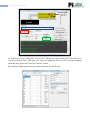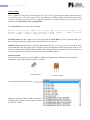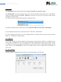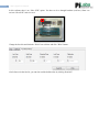
1
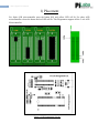
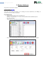
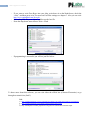
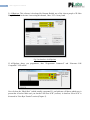
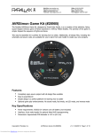
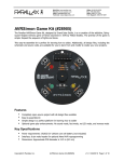
User Manual
Of
AVR Programmer
2
AVR Programmer Manual
Contents
Contents……………………………………………………………………………………. 2
1. Placements…………………………………………………………………………. 3
2. Burner Software…………………………………....………………………………. 4
3. Fuse Bytes Tutorial………………………………………………………………… 9
4. Troubleshooting……………………………………………………………………14
3
AVR Programmer Manual
1) Placement
For 40pin AVR microcontroller press the button (B1) and yellow LED will lit. For other AVR
microcontroller release the button and red LED will lit. This Programmer supports all the 5 volt AVR
Microcontroller.
2nd pin
4th pin
Figure: AVR Programmer Layout
4
AVR Programmer Manual
2) Burner Software
We provide two open source software:
1) Extreme Burner (site link):
At the time I am writing this manual, V1.2 is running. No need to install Driver for USBasp, its
included in the Extreme Burner Installation.
Programming Steps:
- Plug the AVR Programmer into your Windows PC.
- Install the “Extreme Burner V1.2”. Driver will be installed with the installation process.
- Open Extreme Burner.
- Under drop-down menu choose your desired chip.
-
Click on the Fuse Bits/Settings tab and choose “Read All” for read your chip‟s Fuse Bytes.
5
AVR Programmer Manual
-
-
If you want to write Fuse Bytes into your chip, write down it on the blank boxes, check the
“write”, and then press write. For more on Fuse Bits settings see chapter 3. Also you can visit:
http://www.engbedded.com/fusecalc/
For loading Hex file press “Open” and browse the hex file.
From the drop-down menu choose Write > Flash
-
If programming is successful you will see just like below:
To know more about this software, you can visit either the official site (eXtreme Electronics) or go
through our tutorial site (link 3).
Link:
1) http://extremeelectronics.co.in/avr-tutorials/gui-software-for-usbasp-based-usb-avr-programmers/
2) http://extremeelectronics.co.in/software/extreme-burner-goes-social/
3) http://techshopbd.com/index.php/tutorial-categories/avr-tutorial/microcontroller-input
6
AVR Programmer Manual
2) AVRpal.net: This software is developed by Hasanur Rashid, one of the closest people of Pi Labs
Bangladesh Ltd. At the time I am writing this manual, I have V2.3.0 in my hand.
Fig: User Interface of AVRpal.net
If AVRpal.net detect you programmer, then “Programmer Connected” and “Firmware Full
Compatible” LED will lit.
Now click on the “Black Box” (which actually represents IC), and software will detect which mcu is
present the zif socket. Make sure you checked “Set Slow SCK” (red box). A detail on “Slow SCK” is
discussed in “Fuse Byte Tutorial” section (Chapter 3).
7
AVR Programmer Manual
So, it detects my mcu (ATmega32). To load “Hex” file browse it from “Select File” (blue box). You
can also read/write fuses. Take great care when you change the fuse bits. If do not know anything
about fuse bits, please read “Fuse byte Tutorial” section.
By using Fuse Editor (green box) you can save fuse byte for specific mcu.
8
AVR Programmer Manual
For instance, I frequently use L=0xE4 / H=0xD9 fuse bytes. So I named it “General 8MHz” and then
press “Save”.
Now if you click on the “Fuse Shortcuts” drop down menu, you‟ll see “General 8MHz”. If you select
it, corresponding fuse bytes will load. If there is another mcu in zif socket other then ATmega32, it
won‟t be available, which prevents write wrong fuse bytes.
As this software is still in beta testing, so always look for updates (red box). Also if you find any bug,
please report it on the site mentioned above.
9
AVR Programmer Manual
3) Fuse Byte Tutorial
I guess many of you were confused when programming AVR fuse bytes. I get many newbie questions like I
programmed AVR but it doesn‟t work. 90% of them always set wrong fuse bytes and make them DEAD or
unusable. In this tutorial first I will discuss about fuse bits and then how to active so called “DEAD” chips.
Introduction
Fuses are an extremely important part programming a chip, but are rarely explained thoroughly. You only need
to set them once, but if you don't do it right, it's a disaster!
You know about flash, EEPROM and RAM as parts of the chip. What I did not mention is that there
are also 3 bytes of permanent (by permanent I mean that they stick around after power goes out, but
that you can change them as many times as you'd like) storage called the fuses. The fuses determine
how the chip will act, whether it has a bootloader, what speed and voltage it likes to run at, etc. Note
that despite being called 'fuses' they are re-settable and don‟t have anything to do with protection from
overpowering (like the fuses in a home).
The fuses are documented in the datasheets, but the best way to examine the fuses is to look at a fuse
calculator such as in “MikroC” compiler. Please collect the latest version. When I am writing this
tutorial I have version 4.6 in my hand.
If you want to enable something in AVR what you do? Most probably you set corresponding bit as „1‟, right?
For Fuse bit its opposite. Here „1‟ means un-programmed or disable and „0‟ means programmed or enable.
Always remember these.
Fuse bit = 0 => fuse bit is PROGRAMMED
Fuse bit = 1 => fuse bit is UN-PROGRAMMED
Open a project. I am assuming that you are using ATmega16. Go to “Project Menu” and click on “Edit Project”
(Shifht+Ctrl+E). A window will open just like below:
10
AVR Programmer Manual
SPIEN bit is for programming. It should be enable for load program into chip. If you disable it you can‟t
program no more. So „MikroC‟ make this fixed and you can‟t change it. If you check other bits (Like: JTAGEN)
you will see the corresponding bits in “Configuration Registers” box (bottom right) changed to Zero. You can
know about other fuse bits in ATmega16 datasheet page 255. I like to mention one thing before I go to next
stage. By default in ATmega16, JTAG enabled by default. That‟s why you can‟t use PORTC2-5 as digital I/O.
So you have to disable it.
Brown-out Detect (BOD)
The first drop down menu is “Brown Out Detect”. These fuses set what voltage to turn the Brownout
protection circuitry on. A brownout for a chip means that the power voltage is too low for it to run
reliably at the speed of the clock.
For example, the attiny2313 can run as fast at 20MHz but only if the power voltage is between 4.5V
and 5.5V. If the voltage is lower than that, it may behave erratically, erasing or overwriting the RAM
and EEPROM. It may also start running random piece of the flash program. To keep it from doing that,
set the brownout voltage to 4.3V, then if the voltage dips, the chip will turn off until the voltage
returns. It will then reset and start over.
If the chip is meant to run at 5V, set the brown-out to 4.3V. If the chip can run as low as 3.3V you can
set the brown-out to 1.8V. If the chip is a 'low voltage compatible' chip such as the attiny2313V (which
can run as low as 1.8V if its clocked at 4MHz or less) then you can set the brownout to 1.8V.
For simplicity, disable it.
11
AVR Programmer Manual
Clock selection
The 2nd option is how the chip is clocked. Every CPU uses a clock, in general one assembly code instruction is
run every clock cycle. The one in your PC has a clock that runs at 1GHz or higher. This little chip runs much
slower. If you look at the menu you'll see a huge list of options, but looking carefully you'll see there are two
groupings, the Clock Source and the Startup Time.
The Clock Source can be either of the following:
External Clock, Internal 8MHz clock, Internal 4MHz clock, Internal 128KHz clock,
External Crystal (0.4-0.9 MHz), External Crystal (0.9MHz - 3.0MHz), External
Crystal (3.0MHz - 8.0MHz) or External Crystal (8.0MHz +)
External Clock means that a square wave is being input into the CLOCK-IN pin. This is pretty rare unless you
have a clock generating chip. Don't use this unless you're sure you mean to.
Internal Clock means that there‟s a little oscillator inside the chip, it‟s not very precise but good for most
projects that don‟t have fine timing issues. The clock varies with temperature and the power supply voltage. You
can choose from a 1MHz, 2MHz, 4MHz or 8MHz clock. Having an internal oscillator means we don't need to
wire up a crystal and we can use the clock pins for our own nefarious purposes.
External Crystal
If you need a special clock rate, like 3.58MHz or 12MHz or a high precision clock that won't drift with the
temperature, you'll want an external crystal or oscillator.
Crystal Oscillator
Clock settings has following options:
Beginners usually use internal 1MHz to 8 MHz. So
choose internal oscillator. For this tutorial I choose
Int. RC Osc. 1 MHz.
Ceramic Oscillator
12
AVR Programmer Manual
Startup time
The Startup time can be either of the following: 6CK + 0 ms, 6CK + 4 ms, 6CK + 64 ms.
The Startup Time is just how long the clock source needs to calm down from when power is first applied.
Always go with the longest setting 6CK + 64ms unless you know for a fact your clock source needs less time
and 64ms is too long to wait.
The “Start-up Time” menu has following options. Choose the 64ms:
By default, chips that come from the factory have the Internal 1 MHz clock with 6CK + 0ms Startup.
So, in configuration register box I see the fuse bits are: LOW: 0xE1 HIGH: 0xD9
It‟s time to load this bit into chip. If you use USBasp hardware for loading, then you must be using “Extreme
Burner” or “AVRpal.net” software I guess.
By AVRpal.net:
If your chip is brand new, then by default its clock frequency set into internal 1 MHz. So, in AVRpal.net you
have to check “Set Slow SCK” box. If you change the fuse bits for higher frequency then you can either “check”
or “uncheck” Slow SCK, your choice. The difference is, when “Slow SCK” is checked the program will load
slowly and vice versa. REMEMBER, if clock set to 1 MHZ, you have to check “Slow SCK” box. Otherwise it
won‟t work.
By eXtreme Burner:
Open the program. Change the tab from “Flash” to “Fuse bits/Settings”, just like below:
13
AVR Programmer Manual
In this software there is no “Slow SCK” option. You have to do so through hardware (red box). Short it to
activate “Slow SCK” and vice versa.
Change the fuse bits and check the “Write” box as below and click “Write” button:
Also before write the fuse bit, you can also read the default value by clicking “Read All”.
14
AVR Programmer Manual
4) Troubleshooting
I think the above tutorial will help you set fuse bits properly. But though what if you set wrong fuse bit? (Most
of the time it happens with pony prog user). Here comes the solution:
If extreme burner does not detect you chip:
1) First check, is “SLW_SCK” pin shorted (for eXtreme Burner) or checked (for AVRpal.net)? If not, then
short/check it and try.
2) If till problem remains then put a crystal (8 or 12MHz, I prefer 12MHz) between XTAL1 and XTAL2
pin, with “SLW_SCK” pin shorted/checked. Then click “Read All”. Most of the time problem will solve
in this stage.
3) If till problem exist then maybe you disable SPIEN bit, which is unlikely, a rare situation, but definitely
it isn‟t for wrong clock fuse bit. If that is the situation then you need high voltage programmer (like
TopWin). Also you can use “Fuse bit Doctor” (Google it!).
4) Check the ATmega16‟s Vcc and GND pin, see if they get between 4.5 to 5.5V.
5) Test short circuit of MOSI, MISO, SCK, RST pin with your multimeter between your programmer and
your chip.
I hope above five steps will solve your problem.
Thank you for using Pi-Labs‟ Product.
Fahad Mirza
Embedded System Engineer
Pi Labs Bangladesh Ltd.
[email protected]
LIMITATIONS
Hardware:
This package includes a circuit diagram. This circuit can only be used
programming 5V target systems. For other systems a level converter is needed.
for