1
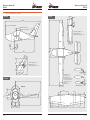
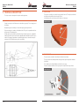
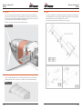
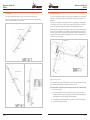
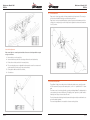
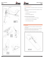
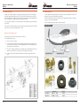
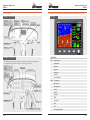
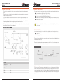
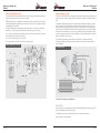
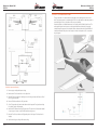
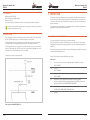
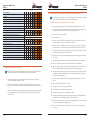
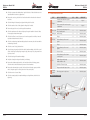
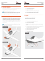
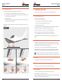
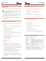
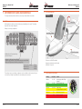
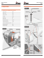
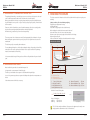
MAINTENANCE MANUAL
UL-AIRCRAFT LTF-UL 2003
Manufacturer No.: FRXXX
Registration No: D-MXXX
Maintenance Manual V001
FRECCIA
Maintenance Manual V001
FRECCIA
CONTENTS
1.General...................................................................................................... 5
4. Ground Handling..................................................................................... 40
1.1. Three-view drawings – Freccia................................................................6
4.1. Relocating the Airplane on Ground......................................................40
1.2.Dimensions..............................................................................................8
4.2.Parking...................................................................................................41
1.3. Lifetime restrictions...............................................................................10
4.3. Tying Down............................................................................................41
1.4. Fuel and other liquids............................................................................11
4.4. Lifting and Levelling..............................................................................42
2. Technical description................................................................................ 12
5. Cleaning and Care.................................................................................... 43
2.1.Fuselage................................................................................................12
5.1. Painted External Surfaces......................................................................43
2.2. Engine cover.........................................................................................13
5.2. Glass Panels...........................................................................................43
2.3. Engine mounts......................................................................................13
5.3.
2.4.Firewall..................................................................................................14
5.4.Engine...................................................................................................43
2.5.Tank.......................................................................................................14
5.5. Cabin interior.........................................................................................43
2.6.Wings....................................................................................................15
2.7.Empennages.........................................................................................16
2.8. Ailerons control.....................................................................................17
2.9. Flaps control..........................................................................................19
2.10. Elevator control.....................................................................................19
Propeller...............................................................................................43
6.REPARATIONS.......................................................................................... 44
6.1. Main wheels’ assemblage and disassemblage......................................44
6.2. Replacement of brakes’ pads................................................................45
6.3. Replacement of the main wheel’s tyre...................................................45
2.11. Trim control...........................................................................................21
6.4. Materials used in manufacturing process..............................................45
2.12. Rudder control.......................................................................................22
7. information signs and Markings............................................................... 46
2.13.Undercarriage........................................................................................23
2.14.Equipment.............................................................................................24
2.15. Primary Flight Display and Engine Monitor System (Dep. Configur.).....25
2.16. Electrical System....................................................................................26
7.1.Panel......................................................................................................46
7.2. Further markings...................................................................................47
7.3. Airspeedindicator Marks.......................................................................47
2.17. Engine – ROTAX 912 ULS......................................................................27
8. RESCUE SYSTEM..................................................................................... 48
2.18. Pitot – static pressure system................................................................31
8.1. Technical data of the Magnum Light Speed Softpack...........................48
2.19.Propeller................................................................................................32
8.2. Installation drawings..............................................................................49
2.20. Brake system.........................................................................................32
8.3. Maintenance of the Magnum Light Speed Softpack.............................50
3.INSPECTIONS.......................................................................................... 33
3.1. Scheduled Airplane Inspections............................................................33
8.4. Maintenance during storage.................................................................50
9. Weighing Procedure................................................................................ 51
3.2. Inspection after 5 hours of flight...........................................................36
3.3. Inspection after 25 hours (at least once a month).................................38
3.4. Inspection after 100 hours of flight (at least once a year).....................38
3.5. Lubrication instruction...........................................................................39
Seite 2
Seite 3
Maintenance Manual V001
FRECCIA
Maintenance Manual V001
FRECCIA
1. GENERAL
This Maintenance Manual is updated regularly. The latest versions can be downloaded as a PDF
file on the Web site of the manufacturer (www.promecc.com). The current version number is printed on each page in the header (V ---).
Respect the copyright! This flight manual may not be copied or distributed without the written
consent of the originator, not even in a modified form.
MANUFACTURER of the aircraft:
PRO.MECC s.r.l.
Zona Artigianale S.S. 16 - Km 976
73022 - Corigliano D’Otranto (LE)
ITALY
www.promecc.com
As for the engine group’s ordinary and extraordinary maintenance, the user must follow the
instructions in Rotax manual.
As for the propeller’s ordinary and extraordinary maintenance, the user must follow manufacturers operating manual’s instructions.
NOTE 1: At the moment for maintenance related to tightening or substitution of detachable match elements you should mark the revised elements with an indelible colour. The
colour must be different according to the kink of maintenance (frequency, replacement,
tightening, etc.). The legend with the colours which have been used and the kind of maintenance which have been carried out will be included enclosed in the aircraft’s maintenance
booklet.
NOTE 2: in any case refer to the manufacturer, to specialized firms or to authorized resellers and render a precise account of maintenances.
All major repairs and spare part replacements MUST be done by authorised service personnel.
However, you are encouraged to take care of preventative maintenance yourself.
This includes:
tire and wheel bearings replacements, safety wire replacements, door and safety harness replacement, light bulb replacements, fuel hose replacements, battery servicing and replacement, sparks
and spark plugs replacements and air filter replacements.
Seite 4
Seite 5
Maintenance Manual V001
FRECCIA
Maintenance Manual V001
FRECCIA
1.1. THREE-VIEW DRAWINGS – FRECCIA
SIEDEVIEW
TOPVIEW
mac=758
35% mac
7004
20°
STATION 0 PROPELLER FLANGE
687
15°
2972
3707 ARM OF VERTICAL TAIL
3885 ARM OF HORIZONTAL TAIL
HORIZONTAL TAIL AREA = 2,2 m2
ELAVATOR AREA = 0,77 m2
HORIZONTAL TAIL ASPECT RATIO = 4,3
600
900
660
8762
1200
4014
2972
1500
645
1400
581
1351
947
25°
VERTICAL TAIL AREA = 1,2 m2
RUDDER
AREA = 0,42 m2
mac
VERTICAL TAIL ASPECT RATIO = 1,4
PIVOT
2111
WING AREA = 10,13 m2
FLAP AREA = 0,66 m2
AILERON AREA = 0,47 m2
ROOT AIRFOIL = NACA 63.2 412
TIP AIRFOIL = NACA 63.2 412
WING ASPECT RATIO = 7,54
SWEEP = 1°
TAPER RATIO = 1,556
FRONVIEW
1938
MAC
66
FUSELAGE
B
A
B
202
1486
900
A
12°
1°
2543
1154
24°
AILERON DEFLECTION
5°
Seite 6
B:B
900
MAX=Ø1900
1153
1600
A:A
1/4 C
1236
35°
A:A
299
1741
1741
8762
Seite 7
Maintenance Manual V001
FRECCIA
Maintenance Manual V001
FRECCIA
1.2. DIMENSIONS
WING
ELEVATOR
Wing span
8,777 m
Elevator span
2,972 m
Wing chord
1,209 m
Surface
0,77 m2
Wing surface
10,13 m2
Stroke
20° (up)
Dihedral
5°
15° (down)
TRIM
AILERONS
Aileron span
1,741 m
Width
0,75 m
Mean chord
0,27 m
Chord
0,075 m
Aileron surface
0,47 m2
Stroke
20°±2° (up)
Steering angle (stroke)
24° ± 1° (up)
12° ± 1° (down)
FLAPS
VERTICAL FIN
Vertical fin span
1,351 m
Flap span
1,741 m
Minimum chord
0,645 m
Mean chord
0,38 m
Maximum chord
1,236 m
Flap surface
0,66 m2
Mean chord
0,947 m
Flaps positions
0° / 35° (down)
Surface
1,12 m2
Extension
1,4
FUSELAGE
Total length
7,248 m
RUDDER
Max width
1,20 m
Surface
0,42 m2
Max height
2,553 m
Steering angle
±25° ± 1°
Frontal surface
1,20 m2
ENGINE
Max section surface
1,00 m
Engine model
ROTAX 912 ULS
Fuselage surface crossed by air flow
14 m
Maximum rotational speed of the propeller
2400/2800 according to the engine model
Maximum rotational speed of the engine
5800 rpm in 5min / 5600
According to the customer’s demand
2
2
TAIL PLANE (HORIZONTAL TAIL)
Seite 8
20°±2° (down)
Wing span
2,972 m
Propeller
Mean chord
0,758 m
UNDERCARRIAGE
Aspect ratio
2,2 m
Width of the rear landing gear (undercarriage)
1,6 m
Extension
4,3
Distance between the turning wheel and the rear
1,5 m
Angle of incidence
+ 1,2
landing gear
2
Seite 9
Maintenance Manual V001
FRECCIA
Maintenance Manual V001
FRECCIA
1.3. LIFETIME RESTRICTIONS
1.4. FUEL AND OTHER LIQUIDS
General overhauls are fixed on 1200 flight hours or 10 year of use.
As for the engine and some special elements, refer to the following table:
CAPACITY
ENGINE COOLING SYSTEM
ENGINE, SYSTEM, PART
LIFE SPAN
SPARE PART REPLACEMENTS
Cooling fluid capacity
ROTAX 912 ULS ENGINE
First overhaul: after 1500
hours or 15 year of use
End of potential
Radiator volume0,600 l
Propeller
See manufacturer’s user manual
End of potential
Engine fittings
According to engine manual
or in accordance with their
state and condition.
End of potential or wear and
tear
Fuel filter
100 h
End of potential
Battery
2 years
End of potential
Fuel and oil sleeves
According to their state and
condition
Wear and tear, damage
Engine mounts and main
undercarriage plate’s silentblocks
According to their state and
condition
Wear and tear, damage
Fuel pump
According to their state and
condition
Breakdown
Brake small pads
According to their state and
condition
Breakdown
OIL
According to their state
Breakdown
Synthetic motorcycle oil from 50W-40 to 20W-50, according to the respective ambient
temperature.
Brake disc
Engine cooling cavities volume
2,160 l
1,410 l
ENGINE LUBRICATION SYSTEM
System total volume
3l
BRAKING SYSTEM
System total volume
0,150 l
FUEL, OIL AND OTHER LIQUIDS
FUEL
Car fuel, at a 90-octane rating for ROTAX 912UL, at a 95-octane rating for ROTAX 912 ULS.
REMARK: the use of leaded petrol is forbidden!
REMARK: The use of oil additives is forbidden!
Life-saving equipment (if it’s
present)
See manufacturer’s user manual
See manufacturer’s user manual
Tyres
According to their state and
condition
Wear and tear, damage
Tools
According to their state and
condition
Breakdown
As the previous table, some elements and subsets must be overhauled or replaced in the aircraft’s
lifetime. The technical staff who guarantee the use of the aicraft must check frequently these elements’ good conditions and dependability and they must replace them, according to their state
and condition.
COOLANT
Car anti-icing used for aluminium-alloy engines.
BRAKE FLUID
Car brake fluid.
Any yielding found out in the use must be put right, and every parts where some yieldings have
been found must be checked carefully.
The list of the elements and the subsets which are subject to replacement is quoted in the engine
manuals.
The replacement and installation techniques of the aircraft’s other elements and subsets are quoted in the respective chapters.
Seite 10
Seite 11
Maintenance Manual V001
FRECCIA
2. TECHNICAL DESCRIPTION
This Section contains a description of the airplane and its equipments.
Maintenance Manual V001
FRECCIA
2.2. ENGINE COVER
The engine is covered by a cover made of a top part and a lower one. The two pieces are fixed to
the fuselage and are fixed each other through collblock.
In the lower part of the cover there are the air intakes to cool the engine.
2.1. FUSELAGE
ENGINE COVER
Fuselage is made up of a shell-like structure in carbon fibre (epoxy resin). Fin is an integral part of
the fuselage.
Wing attaching points are made up of 2 carbon fibre spars going through the shell.
Engine mounting pylon is made up of welded steel tubes. The engine is separated from the fuselage by means of a firewall protection.
Cockpit seats are positioned side by side and their shape is rigid and ergonomic, not adjustable.
Safety belts have three junction points and are adjustable and provided with a single lock easy to
unfasten. The baggage compartment is located behind pilots seats, it is allowed to transport a
maximum of 10-kg. A Plexiglas canopy can be opened lifting.
2.3. ENGINE MOUNTS
The engine mounts are made of a three-dimensional frame with steel tubes.
The engine mounts have the fittings with the fuselage and the engine through bolts and rubber
silent blocks.
The oil radiator and cooling-fluid radiator are installed on some props.
The order of radiators’ installation in the engine systems is explained in the engine manual.
ENGINE MOUNTS
Engine only principle illustraion
Seite 12
Engine mount
Seite 13
Maintenance Manual V001
FRECCIA
2.4. FIREWALL
The firewall is a structural element situated on the front part of the fuselage and it separates the
engine from the cabin. It’s made of a composite-material panel. The part of the panel which is turned to the engine has the attachment fittings for supporting the battery case, for the oil tank and
for other components of the power plant and the aircraft systems.
The firwall is covered by a special material heat and flame resistant.
Maintenance Manual V001
FRECCIA
2.6. WINGS
The aircraft is provided with a low and tapered wing made up of 2 half-wings in carbon fibre that
can be disassembled, with a main spar going through the fuselage and with a wing rib equipped
with wing-fuselage connection points. Wing tips can be removed.
The structure of wing, flap and aileron is identical to the one of tail unit.
FIREWALL
2.5. TANK
The tank are made of fibreglass and are in the right and left wing-halves. At the rear they have a
cylindrical screwing which is set in the hole rib; on the front it is secured to aluminium ribbing.
TANK
Seite 14
Seite 15
Maintenance Manual V001
FRECCIA
2.7. EMPENNAGES
Classic type and provided with rudder, tail plane, elevator and trim electrically moved.
It is made of composite materials with a shell of sandwich panels composed of carbon glass fibre
and p.v.c. and the spar made of p.v.c.-carbon fibre.
Maintenance Manual V001
FRECCIA
2.8. AILERONS CONTROL
The ailerons control is differential (when the right aileron moves upwards, the left one goes downwards and vice versa). The angle of steering on the upwards is wider than the angle of the one
downwards.
The aileron course compared to neutral position is of 24° ±1° upwards and 12° ±1° downwards.
The consequence is the increase of ailerons’ efficiency especially in the big-incidence flight, also
to make up for the different curvature between the back and the underside of the wing.
Replaced through connecting rods and transfers, they efforts on the control handle are passed on
the wing. The controls assembly connects the right control stick with the left one and vice versa.
From each of them a transfer is connected to the respective wing through an extesible-head connecting rod. From that a bar inside the wing transmits the movement to the last transfer, integrated into one of two aileron hinges.
Rigging of Ailerons Control
In a neutral position the ailerons’ aft edge must be on the same line as the back part of the wing
tip; the maximum admissible difference upwards or downwars is of 2 mm.
Check if the positions at the end of ailerons running are correct. If it isn’t, follow these steps:
1 Put the aileron upwards;
2 Loosen the push-rod locknuts which are under the wing. Act on the internal nut, by unscrewing top ut the aileron up or by screwing top ut it down, until its trailing edge has the
indicated distance from the tip’s aft edge (limit switch upwards).
3 Consequently the limit switch downwards is correct thanks to the aileron’s tranfer design.
4 Screw and lock the external checknut.
Seite 16
Seite 17
Maintenance Manual V001
FRECCIA
Maintenance Manual V001
FRECCIA
2.9. FLAPS CONTROL
Flaps control is electric-type, made of a linear actuator driven by electric switch. The control system is positioned inside the fuselage, accessible removing the trunk.
Flaps control is an electric switch with up-down positions located on the instrument panel in the
cockpit, on the control panel; by means of it flaps can be adjusted in continuous movement from
0° to 35° positions.
Control-stick adjustment
If the control stick is in a neutral position and the ailerons are not lined up with the respective tips, act as follows:
1 Remove the door on the seats’s floor;
2 Unscrew the M6 nut to take off the connecting rod from the control-stick transfer;
3 Fix the aileron and the control stick in a neutral position;
4 The connecting rod goes up an adjustable head: unscrew the control for some turns and
rig the head until it can enter easily in the control-stick bolt;
5 Screw again the M6 nut and lock the checknut;
6 Close the door.
2.10.ELEVATOR CONTROL
The stabilizer is slightly in nosedive position to facilitate the aircraft nose-up, especially on takeoff. The elevator travel, respect to the neutral position, is of 20° +-1° upward and 15° +-1° downward.
The elevator control is consisting of handle, connecting rod and quickdraw. The duralumin tube is
connected to axis, by means of ball bearing. The flapping of the “pushed” or “pulled” handle is
limited by control stops on the two sides of the axis.
The axis is fastened to the fuselage frame’s bottom tube through two bolts; around them the control stick is rotated lenghtwise.
The control-stick quickdraw is connected to the elevator one through a bar.
Seite 18
Seite 19
Maintenance Manual V001
FRECCIA
Maintenance Manual V001
FRECCIA
Adjustment of The Elevator Control
The control stick’s neutral position in the cockpit must correspond to the elevator control’s neutral
position.
The rigging of the elevator’s angles of steering is possible through an adjustable connecting-rod.
To modify the length:
1 unscrew the connecting rod from the elevator’s bellcrank ;
2 unscrew the locknut;
3 then screw or unscrew the adjustable head.
Check of the system is made in the following points:
1 open inspection hole below the fuselage to have access to stick group
2 remove the trunk to have access to the control quickdrarws
3 check nuts and locking nuts of the system.
2.11.TRIM CONTROL
Trim adjusts the elevator position in a more accurate way to avoid continual corrections by the
control stick in flight.
Its movement is electric controlled by a switch located inside the cockpit, on the stick grips and
which transmits the movement to the actuator, positioned inside the elevator.
Adjustment of the travel is possible by the pushrod that join the actuator to the trim bellcrank.
Seite 20
Seite 21
Maintenance Manual V001
FRECCIA
2.12.RUDDER CONTROL
Rudder control constists of pedals, connecting rods, bearings, bowed cables. The left and right
pedals have independent-rotation axles. Two cables, the left one and the right one, are fixed on
the eyelets welded to the pedals. The cables are fixed on their other edge to the rudder bellcrank
which are installed on the rudder through a plate glued and screwed.
The control system ends with the connecting rods which link the pedals to the front undercarriage
(nose wheel).
The control stops of rudder steering are put on the support of the steering bellcrank. The rudder’s
angle of steering on the left and on the right is of ±25°.
Maintenance Manual V001
FRECCIA
2.13.UNDERCARRIAGE
It is a fixed three-wheel undercarriage with a turning nose wheel and disc brakes on the main landing gear. Fairing are installed as optional components
The front undercarriage leg is made of steel and it is provided with shock absorber. Front undercarriage is connected to rudder pedals.
The main undercarriage legs are made of composite materials.
UNDERCARRIAGE
Adjustment of The Rudder Control
The angles of steering from the neutral position are of ±25° ±2°.
As for the adjustment you must:
1 Put the nose wheel in neutral;
2
It is necessary that neutral position of the rudder pedals correspond to neutral position of
nose wheel. Access to nose wheel – rudder pedals pushrods for check and adjustment are
two inspection holes on the firewall.
3 Then check or adjust the uniball that connect Bowden cable to rudder bellcrank so also the
rudder is in neutral position. The cables cross at the back part of the fuselage.
4 At the end, they must be tightened gradually until the rudder is straight and it doesn’t
move.
Steering Nose Wheel
Main Undercarriage
Dymension
Nose wheel
Main wheel
Seite 22
4.00 – 4”
8 ply
13x5.00 - 6” 4 ply
Pressure
1.5 bar
1.8 bar
Seite 23
Maintenance Manual V001
FRECCIA
Maintenance Manual V001
FRECCIA
2.15.PRIMARY FLIGHT DISPLAY AND ENGINE MONITOR SYSTEM (Depending Configuration)
2.14.EQUIPMENT
PFD / EMS
MINIMUM CONFIGURATION
Control lamps
1 Generator
2 Battery
3 Fuel Pump
Switches
1 Main Switch
2 Fuel Pump
3 EFIS / EMS
Display Trim
Switch
Left Stick <-> Right Stick
Primary Flight Display
Engine Monitor System
Choke
Ignition Switch
Breakers
Ignition Switch
Tactile for Trim
DESCRIPTION
MAXIMUM CONFIGURATION
This cockpit shows the maximum configuration with analogue instruments. The equipment can
be configured differently. Therefore deviate the actual features of this figure.
Control lamp
- Battery
- Fuel Pump
- Generator
PFD
Anemometer
Altimeter
Navigation System
Flight Instrumens
Artificial horizon
Compass
Engine Instruments
Variometer
Switches
1 Main Switch
2 Fuel Pump
3-8 Depends on config.
G-meter
Turn coordinator
EMS
Switch
Left Stick <-> Right Stick
Display Trim
Ignition Switch
Fuel pressure
Oil pressure
Oil temperature
2x CHT
2x EGT
Voltmeter
RPM
Tactile for Trim
Breakers
Hour meter
MAP
OAT
Choke
Seite 24
Carburator Heating
Cabin Heating
Fuel quantity indicator
Seite 25
Maintenance Manual V001
FRECCIA
Maintenance Manual V001
FRECCIA
2.16.ELECTRICAL SYSTEM
2.17.ENGINE – ROTAX 912 ULS
The aircraft is equipped with a 12-volt, direct-current electrical system with grounded negative
pole.
The primary source of electrical energy is provided by the engine mounted interior alternator/generator with total power of 750 W.
The internal alternator located at the rear of the engine block will charge the battery up to 13.5
VDC.
Power is supplied to the electrical and avionics circuits through a main bus bar located behind
instrument panel, this bus bar is energized anytime the Main switch is ON.
Each system is protected by circuit breaker which is permanently on. If some circuit is overloaded,
then the circuit breaker disconnects that circuit.
For engine inspection and maintenance refer to original Rotax manuals supplied with the aircraft:
■■
■■
■■
■■
■■
Operator´s Manual for ROTAX engine Type 912 Series
Documentation for ROTAX aircraft engines (CD – ROM)
Service instruction fur ROTAX Type 912 und 914 (series)
ROTAX service letter Warranty conditions for ROTAX engine types 912 and 914 (series)
ROTAX engine Log book
Engine removal, installation and replacement can only be done by Pro.Mecc authorized
service center.
ELECTRICAL SYSTEM
ENGINE CONTROL
On the central control panel, in the middle of the cockpit there are the handgrips relative to:
■■ Throttle lever
■■ Choke push pull cable
The power levers and the choke one are fixed to a control box made of carbon fibre and they are
linked to steel-sheath cables.
The cables, fastened to the fuselage structure, pass the firewall and inside engine compartment
are fixed to a box that has the function to double the controls in order to reach the throttle lever
and the choke lever of the two engine carburetors.
ENGINE CONTROL
Sheath
Lever
Fuel lever
Quick draw
Control-engine cable
Control box
FUSES
Start Armed
2A
Fuel Pump
2A
EFIS
3A
Flap
3A
Trim
1A
Seite 26
Adjustment of engine control
The engine-control lever must move with a right effort. In case of effort’s weakening, in flight the
lever could move ahead spontaneously and the engine’s power setting would increase. In this
case, adjust the engine choke lever. Loosen the M8 nut, lock it with a proper spanner and secure;
consequently, the friction increases and the engine’s control lever remain in a more appropriate
position.
Seite 27
Maintenance Manual V001
FRECCIA
Maintenance Manual V001
FRECCIA
ENGINE LUBRICATION SYSTEM
ENGINE COOLING SYSTEM
The engine lubrication system limits the wear and tear of the engine elements and ensures their
partial cooling and evacuate the rejects of wear and tear.
The function of ROTAX 912 UL(S) cooling system is to guarantee liquid cooling for cylinders heads
and air cooling for cylinders. Cylinders heads cooling system is at closed circuit with an expansion
tank.
ROTAX 912 UL(S) engine is equipped with a dry sump forced system including a main oil pump
with an integrated pressure regulator (1) and a oil-pressure sensor (2). The integrated oil pump is
activated through the camshaft.
The oil in excess overflowing from the lubrication points accumulates in the bottom of crankcase
and it’s pushed back, to the tank by blow’s gas.
Cooling fluid is pushed by the pump (set in motion through camshaft) from radiator to cylinders
heads. From the top of cylinders heads, cooling fluid reaches the expansion tank (1). Since, usually, the radiator position (2) is lower than the engine one, the expansion tank located above the
engine allows the cooling fluid to flow. Expansion tank, shut with a pressure cap (3) provided with
overpressure valve and return valve, opens and cooling fluid runs through an atmospheric pressure tank to a transparent overpressure container (4). When cooling temperature begins to decrease,
fluid is sucked down to cooling circuit.
The oil circuit is vented by a bore on the oil tank.
Cooling fluid temperatures are measured by sensors installed on cylinders heads 2 and 3.
The oil-temperature sensor (8) is located on the oil pump housing.
Temperature readings are taken by measuring the hottest point of cylinder head, according to
engine installation.
Through the depressurizing created by the pump (3), the engine oil is driven from the tank (4)
through the oil cooler (5), through the filter (6) to the lubrication points in the engine.
ENGINE LUBRICATION SYSTEM
COOLING SYSTEM
Coolant Fluid: see Engine Operator Manual.
FUEL SYSTEM
Freccia in basic version is equipped of a fuel tank installed inside right wing, having capacity of 50
liters. The drenable quantity of fuel is 48.5 liters.
It is available as option the second fuel tank that can be installed on the left wing.
System schema is represented below.
Seite 28
Seite 29
Maintenance Manual V001
FRECCIA
Maintenance Manual V001
FRECCIA
2.18.PITOT – STATIC PRESSURE SYSTEM
The pitot-static tube is located under the leading edge of the right wing and consists of a air
duct. Total system pressure is sensed through the hole in the pitot-tube face and static pressure is
sensed through the holes on both sides of the rear part of fuselage.
Pressure distribution to individual instruments is received by means of flexible plastic hoses. The
tube supplies dynamic ram air pressure to the airspeed indicator, and the static ports supply
outside atmospheric pressure to the airspeed indicator, altimeter, and vertical speed indicator. If
installed, the altitude hold portion of the autopilot or mode C transponder is also connected to
the pitot system.
Static Pressure System
Static Pressure System
Gascolator inspection/cleaning
1 Remove upper cowling and bottom cowling.
Pitot Pressure System
2 Make sure the Fuel Selector Valve is in the off position.
3 Drain the Fuel gascolator by the draining vent on the fuel gascolator tank. Remove all fuel
from Fuel gascolator tank.
4 Remove Fuel filter tank from the Fuel gascolator
5 Clean Fuel gascolator fuel strainer and sediment bowl. Inspect the Fuel gascolator sealing
for condition, replace it if damaged.
6 Install back Fuel filter tank from the Fuel gascolator. The rest of the Fuel filter tank installation process goes in reverse to the Fuel filter tank removing process.
7 Move the Fuel Selector Valve to the Right tank position ON. Inspect Fuel Gascolator for
leakage.
8 Install back the Upper cowling and Bottom cowling.
Seite 30
Seite 31
Maintenance Manual V001
FRECCIA
2.19.PROPELLER
Manufacturer: DUC HELICES
Model: 3-blade Inconel SWIRL clockwise
Diameter: 1730 mm
For propeller inspection and maintenance refer to original propeller manufacturer´s Manuals.
Propeller removal, installation and replacement can only done of Pro.Mecc or propeller manufacturer authorized service center.
Maintenance Manual V001
FRECCIA
3. INSPECTIONS
This section contains some requirements concerning inspections and basic maintenance, which
are to be observed in order to maintain the performance and reliability of a new airplane. It also
contains procedures for the correct handling of the airplane and servicing, recommended by the
airplane manufacturer.
It is reasonable to proceed according to a prescheduled scheme of lubrication and maintenance,
appropriate to the operating conditions and climate.
2.20.BRAKE SYSTEM
The braking system consists of one brake lever positioned in the middle of control panel, that by
the mean of a brake pump operate on the two brake system on the rear wheel.
The left and right brake share a common fluid reservoir installed on the top right of the firewall.
Care must be taken to avoid applying brake pressure when using rudder on the ground.
The parking brake control valve is mounted in the middle of the two seats, rear to the central control panel. The parking brake is OFF if the control lever is rotated vertically upwards, and it is ON
if the control lever is rotated orizzontally to the sense of flight.
Schematic of the system is represented below.
3.1. SCHEDULED AIRPLANE INSPECTIONS
The scope and the intervals of the inspection schedule are defined.
Tasks to be carried out in relation to scheduled inspections of engine, propeller, rescue system
and equipment, are defined in the respective applicable manuals or operating and maintenance
instructions.
The owner and operator are responsible to insure that all handling, servicing and maintenance are
only carried out by qualified personnel.
The table below indicates recommended maintenance periods.
Table legend:
C
Check-up - visual only, check for free play and whether everything is in position
DO IT YOURSELF
CL
Cleaning
DO IT YOURSELF
LO
Lubricating, oiling - lubricate all designated parts and spots using proper lubricant
DO IT YOURSELF
R
Replacement - replace designated parts regardless of state and condition.
You are encouraged to DO undemanding replacements YOURSELF, otherwise have
replacements done by AUTHORISED SERVICE PERSONNEL
SC
Special check-up - measuring, verifying tolerances and functionality
DONE BY AUTHORISED SERVICE PERSONNEL ONLY
O
Overhaul
Fluid replacement: BRAKE FLUID DOT 4.
Seite 32
Seite 33
Maintenance Manual V001
FRECCIA
Maintenance Manual V001
FRECCIA
Daily
first 5
25
hours hours
200
hours
500
hours
1000
hours
10 000
hours
C
LO
C
CL
C
LO
SC
LO
LO
C
C
SC
SC
SC
SC
SC
SC
SC
O
O
O
C
C
C
C
C
wheel fairings
C
C
C
C
C
C
C
C
C
C
C
C
C
C
C
C
C
C
C
C
C
C
C
C
C
C
C
C
C
C
C
C
C
C
C
C
C
SC
SC
SC
SC
SC
SC
C
CHECK LIST FROM ENGINE’S MANUFACTURER MANUAL
CHECK LIST FROM PROPELLER MANUFACTURER MANUAL
WING AND TAIL SURFACES
surface and structure condition
deflection without free play
bearings - moving parts‘ bushing
Lights (if installed)
self-adhesive sealing tape
horizontal tail mount
drain holes
FUSELAGE
surface and structure condition
elevator control tube bearing
undercarriage struts attaching points
doors, hinges
rudder control wires and hinges
CABIN
control levers, instrument panel, seats
control levers‘ free play
instruments and pitot-static
glass surface: clean, attached
safety harnesses and attach. points
parachute rescue system activation handle
wing connectors: fuel, electrical
bolts and spar pins
wing main bushing, control connectors
UNDERCARRIAGE
tires
main strut, tail/nose wheels strut condition
wheel axis and wheels
hyd. brake lines
brake fluid
brake discs
wheel bearing
Seite 34
C
LO
C
C
C
C
100
hours
SC
SC
SC
SC
SC
SC
SC
SC
SC
SC
check yearly
C
C
C
C
C
C
C
SC
SC
SC
general free play
control stick
rudder pedals (damage, centered,paral.)
rudder wire rope
bolts, visible bearings (tail, fuselage)
difficult-to-reach bearings (wings, under cabin floor)
aileron, elevator and rudder hinges
flap handle
elevator trim
ENGINE
In addition to Rotax manual:
SC
engine cover screws
engine mount
engine mount dumpers and other rubber parts
air filters
electric terminals, joints and connectors, hoses, radiator mount
exhaust muffler
exhaust pipe springs and fire protection
throttle, choke, propeller wire drive
ENGINE CONTROL
choke and throttle lever wire ropes
O
replace on condition or every 5 years
R
fastening bolts
propeller pitch
propeller balance
R(500 hrs or 5 years)
(R on condition)
R
C
LO
C
C
C
LO LO
C
C
SC
SC
SC
SC
SC
SC
SC
SC
SC
SC
LO+SC
SC
R
C
C
C
C
C
C
C
C
C
C
C
C
C
C
C
C
SC
SC
CL
SC
SC
SC
SC
C+LO
C
R every 500 hrs or 5 years
SC
SC
SC
SC
R
R
R
O
See manufacturer‘s manual
C
C
C
C
FUEL SYSTEM
C
R
SC
SC
O every 500 hrs or 5 years
CL
SC
CL
SC
SC
CL
SC
SC
CL
fuel valves and leakage
C
C
C
C
C
general leakage
PROPELLER AND SPINNER
surface condition
SC
C
C
C
C
C
C
C
C
four-strokes engines (overhaul every 2000 hours)
levers
see manufacturer‘s manual
C
C
C
CONTROLS (LO every 100 hrs or yearly)
water inside gascolator
dirt and gascolator filter
wing fuel tank caps
fuel tank caps o-ring
SC
SC
R
R every 500 hrs or 5 years
Seite 35
Maintenance Manual V001
FRECCIA
ELECTRICAL WIRING
battery
battery fluids
instrument panel wires and connectors
NAV, AC and LDG lights
fuses
Maintenance Manual V001
FRECCIA
C
C
C
OIL AND WATER LINES
oil and cooling fluids level
oil and cooling fluids leakage
C
C
C
SC
SC
SC
SC
C
C
refer to engine manual
cooling fluid (level)
refer to engine manual
C
C
radiators
water radiator pressure caps
PITOT-STATIC LINING
instrument to pitot tube lining
instrument setting
pitot tube condition (clean, firmly attached)
whole pitot-static lining
R
O evry 500 hrs or 5 years
four-stroke engines oil (and engine filters) first 25 hours
hoses
SC
SC
SC
R
C
C
C
C
C
C
SC
Note: the inspections on engine after 100 hours of flight must be carried out in accordance
with the engine’s operating manual, as well as the following hours.
In addition to the inspections after the first 25 hours of flight
1 Make sure that the battery is disconnected and that the supply-system valve is locked.
2 Check the lower part of wings and the engine cover, by making sure of the absence of petrol leaks from the fuel tanks, and of oil leaks from the lubrication system.
3 Check the fixing of propeller spinner.
4 Remove the covers.
SC
O
refer to engine manual
C
C
3.3. INSPECTION AFTER 100 HOURS OF FLIGHT (AT LEAST ONCE A YEAR)
5 Check the engine, by making sure of the absence of fluids’ leaks from the joining of the
tubes and of the engine, as well as the fixing of the elements.
6 Make the engine turn and make sure of the good working of all cylinders. In case of cylinders which are not so much warmed-up or overheated, identify the reason of this event.
7 Clean the cover, the engine, the propeller, the elements, the tubes, the cables, the filters of
the radiator and of the cooler from the oil remains.
8 Clean the aircraft covering and the undercarriage from dirt and dust. Tidy up the inside of
the cockpit.
9 Check the fuel and oil reserves in the tanks and weigh up their respective consumptions.
10 The check-up steps is the same as the pre-flight check-up in the Flight Manual.
3.2. INSPECTION AFTER FIRST 25 HOURS
Note: the inspections on engine after the first 25 hours of flight must be carried out in accordance with the engine’s operating manual, as well as the following hours.
1 Verify the correspondence of the final positions of the engine’s control lever and the
choke’s control with the carburettors’ levers.
2 Remove the wheels’ fairings, lift the wheel and check it as regards the presence of axial
play, check the condition of the brakes’ discs, of brakes’ brackets. Check the tyres’ pressure.
3 Check the correspondence of the neutral positions of rudders, of flaps and of ailerons with
the neutral positions of controls and of control stick. Check how the control levers work
when smoothly.
11 Check the conditions of the undercarriage’s axes and the mounting tools on the fuselage
frame. Check that there aren’t any cracks or deteriorations at the welding spots.
12 Check the wheels, verify the condition of the rims about the presence of cracks or deformations. Make sure of the good fastening of the wheels’ fixing nuts. Check the tyres, verify if
there’s an irregular consumption.
13 The tyres must be replaced in the case of these defects: Anomalous inflation in a part of
the tyre
14 Wear of the covering throughout, to the chord
15 Cuts and tears on the covering for more than 30 mm
16 Verify if the tyres aren’t turned compared to the rims.
17 Verify the tyres’ pressure: Front 1,6 bar, Maingear 1,8 bar).
18 Check the tubes of braking circuit by making sure of the absence of brake fluid. Make sure
of the absence of cracks and of deteriorations of the wheels’ fairings.
19 Check the wing relatively to the absence of cracks and deformations. Check the wing, flap,
aileron’s covering about the paint’s deterioration.
20 In case of cracks or slivers of the lacquered varnish it’s necessary to renovate through a
second coat.
Seite 36
Seite 37
Maintenance Manual V001
FRECCIA
21 Check by a protractor the rudder surfaces’ angles of deviation. If these deviations are more
important than their tolerances, adjust them.
Maintenance Manual V001
FRECCIA
3.4. LUBRICATION INSTRUCTION
UNIT
22 Remove the cover’s top, check the fuel circuit’s tubes and the valves about the absence of
fuel leaks.
23 Check the fixings of the battery box, tighten the fixing bolts if need be.
1
AREA OF LUBRICATION
Engine
24 Check the attaches of the oil tank, tighten the fixing bolts if need be.
25 Remove the propeller cone, check the propeller’s attachments.
26 Check the attachments of the tubes and of propeller-engine installation’s electrical cables.
If necessary, do the attachments again.
27 Check the fuel filter. In case of the presence of anomalous particles in the filter, it must be
replaced and the tank must be cleaned.
30 Open the inspection panels and check the cables’ attachment fittings, check all the control
cables’ channelling. Possible pulleys must spin easily, without any noises, they mustn’t have
any traces of wear.
33 Remove the aft undercarriage’s wheels, check and clean the wheels’ bearings, grease.
Check the wheels’ axle shafts about the presence of breaks and wear.
34 Remove the undercarriage’s nose wheel, check and clean its bearings, grease, settle the
wheel. Change the grease in all the joints and in all the control planes.
35 Check the tension of control cables.
36 Check the actuating rods, their attachment fittings to the quick draws, check the bolts’
tightening.
LUBRICANT
Throttle control cable into engine
compartment
X
X
Light oil
Choke control cable into the engine
compartment
X
X
Light oil
Nose gear
Nose gear leg and bearing of the
link to rudder pedals
X
X
Lubrication grease
3
Main gear
Axle bearings
X
X
Lubrication grease
Hinges
X
X
Lubrication grease
Rod end bearing of the control
system
X
X
Lubrication grease
Hinges
X
X
Lubrication grease
Rod end bearing of the control
system
X
X
Lubrication grease
Actuator hinges
X
X
Lubrication grease
Rod end bearing of the elevator
control system
X
X
Lubrication grease
X
X
Lubrication grease
Stabilizer – Elevator hinges
X
X
Lubrication grease
Hinges and movable parts of trim
X
X
Lubrication grease
All moving parts in cockpit area
X
X
Lubrication grease
4
Ailerons
5
Flaps
31 Check the fuselage shell’s attachment fittings.
32 Verify the electrolyte’s voltage and its density in the battery.
100 H
2
28 Check the undercarriage’s attachment fittings about the movement, the axle’s wear and the
undercarriage’s elements.
29 Check the covers’ locking, lubricate them.
25 H
6
7
Rudder hinges and bearing
Tail
Rudder Bowden cable
Rudder
pedals
LUBRICATION OVERVIEW
1
7
6
2
3
Seite 38
4
5
Seite 39
Maintenance Manual V001
FRECCIA
4. GROUND HANDLING
The dimensions of the standard airplane are given in the airplane drawings. This allows the size of
the area required for the airplane in a hangar or for parking to be defined.
Note: the size of the required area is to be increased
Respectively, to provide space for supplementary equipment such as antennas of radio
equipment (or other equpment installed according to the operators options).
Maintenance Manual V001
FRECCIA
4.2. PARKING
1 1. Position the airplane pointing into wind.
2 2. Apply chocks to the main wheels.
3 3. Secure the control sticks with the seat belts (or tow bar gust lock).
4 4. Lock the cockpit canopy and apply a canvas cover, if available.
4.3. TYING DOWN
4.1. RELOCATING THE AIRPLANE ON GROUND
If using the towing bar on a level surface, one person is able to move the airplane. The tow bar
is to be fixed to the nose wheel by means of two lugs. If the ground is not even and there are
difficulties in moving the airplane, two people may manage the relocation, balancing the plane on
the main wheels. One person should guide the wingtip and the other should control the movement with the tow bar.
Do not push or pull the airplane by control surfaces and fairings. Push not on the wings,
except the position in following illustration
FORWARD HANDLING
If available, lugs for the tie-down for roping the airplane.
When tying down, the following should be observed:
1 1. It is recommended to have the airplane pointed into wind.
2 2. Put chocks in front of the main wheels.
3 3. Apply locks to the ailerons, rudder and elevator, or fasten the control sticks with safety
belts.
4 4. Put the ropes through the specified lugs and attach the rops to the ground anchors. There should only be slight tension on the tie-downs to prevent sagging.
5 5. Apply the cover to the pitot and static pressure sensors.
6 6. Lock the canopy and put on the cover.
7 7. Position the propeller horizontally
TYING DOWN
BACKWARD HANDLING
Seite 40
Seite 41
Maintenance Manual V001
FRECCIA
4.4. LIFTING AND LEVELLING
When jacking the airplane the following procedure should be followed:
1 Put a stand (under a rib) under each wing to prevent the airplane from tilting.
2 Locate jacks under the nose landing gear ferrule and the other each side next to the cabin
walls, under the main landing gear box.
3 Apply wooden blocks.
4 Lift the airplane gradually to the required height. Lift the airplane, raising each jack evenly
at the same time and avoid swaying.
Maintenance Manual V001
FRECCIA
5. CLEANING AND CARE
It is essential for the reliability of the airplane components to always keep them clean.
5.1. PAINTED EXTERNAL SURFACES
Prior to clean, take the following steps
1 Protect the wheels, especially the brake discs, covering them.
2 Put the cover on the pitot and static pressure sensors.
After lifting, the airplane should be leveled, so that the cabin wall edges are horizontal (see the
illustration).
LEVELLING
3 Mask off all holes and orifices.
Use clean water to remove all fine particles and then wash the surface with water adding mild
soap. Do not use detergents or soaps which are acid, alkaline or abrasive.
To remove spots of grease or oil, use a piece of cloth with degraseing solvent.
After use of degraseing solvent the surface should be re-waxed and polished.
To polish the painted surfaces, a soft cloth or chamois leather should be used.
Aged painted surfaces can be treated with automotive waxes or good quality polishing compounds.
5.2. GLASS PANELS
The greatest care should be taken to avoid scratches when cleaning glass panels of plexiglass.
Never wipe the glass panels when dry. Rinse the panel with clean water or solution of mild soap
and then wipe with soft clean cloth, sponge or chamois leather.
To remove films of oil or grease, use tribasic sodium phosphate, well dissolved in water.
Sediments of grease or oil, if difficult to remove, should be cleaned with methanol, hexane, or
naphtha. Finally rinse with clean water avoiding excessive rubbing of the glass panel surface.
Caution! Do not use petrol, benzene, acetone, anti-icing compounds, or paint solvents,
because these substances soften the plexiglass, or may give rise to a network of fine cracks
5.3. PROPELLER
The propeller is to be cleaned in the same way as the painted surfaces.
5.4. ENGINE
The engine is to be cleaned as indicated in the Engine Maintenance Manual.
5.5. CABIN INTERIOR
The seats, carpets and upholstery have to be cleaned with a vacuum cleaner.
Do not use water to clean items of cloth or fabric.
Foam-based shampoos for general use on automotive upholstery may be applied, but the indications given on the packing should be strictly observed.
Seite 42
Seite 43
Maintenance Manual V001
FRECCIA
6. REPARATIONS
Any repair or modification of the airplane design may only be performed by authorized personnel.
Note: prior to any modification or reparation of the airplane, consult with and obtain written approvement by the manufacturer, that the intended modification will not negatively
affect the airworthiness of the airplane.
After completing the modification, according to the instructions given in the Airplane Maintenance Manual, the aircraft should be re-weighed, and the respective weighing report sheet completed and the Weight and Balance schedule of this manual must be revised.
For every reparation consult with manufacturer to have the lamination and reparation plan, showing picture of the damage.
6.1. MAIN WHEELS’ ASSEMBLAGE AND DISASSEMBLAGE
As for the main wheels ’assemblage and disassembling, at first remove the wheels mudguards. Then:
1 Put a jack under the iron tools which secure the undercarriage to the fuselage and jack the
wheel up
Maintenance Manual V001
FRECCIA
6.2. REPLACEMENT OF BRAKES’ PADS
As for the replacement of brakes’ pads and of brakes’ discs, follow these steps:
1 Remove the wheel
1 Disconnect the wheel from the brake disc and from the support
2 Dismantle the calliper
3 Replace the brakes’ pads in the support and the brake discs, when they are worn out.
6.3. REPLACEMENT OF THE MAIN WHEEL’S TYRE
To replace the tyre:
1 Empty the air from the tyre
2 Remove the tyre from the rim
3 Push the valve in the rim hole and remove the inner tube (if it’s present)
4 Check the rim, clean it
2 Unhook and unscrew the spacer on the wheel axle-shaft
5 Dry-clean the internal surface of the tyre
3 Remove the wheel from the axle-shaft
6 Put the tyre again (with the eventual inner tube) in the rim
4 Wash the bearings with gasoline and dry by blowing air
7 Inflate the tyre till the adequate pressure (2,0-2,2 kgf/cm², approximately 2 bar).
5 Check the bearings to found out eventual damages or corrosions. In case of need, replace
them
6 After the check-up, grease the bearings
7 The assemblage and the disassemblage of the wheel and of its fairing follow the reverse
order with regard to the disassemblage.
8 Then pump the braking circuit.
PUMPING OF BRAKING CIRCUIT
The pumping of braking circuit needs two operators:
1 First of all, install a PVC tube on the relief valve, cleaned from dust and incrustations.
2 The other edge of that tube must be dipped in a container to recover the brake fluid.
3 An operator puts on the brake lever and keeps it locked in “brake” position until the end.
The other operator, following the order of the first one, unscrews the valve of two turns and
checks the flowing of air bubbles from the braking circuit.
4 In this way, the first operator causes the overflow of air bubbles until the stop and asks the
second operator for screwing well the valve. Then he releases the brake lever.
6.4. MATERIALS USED IN MANUFACTURING PROCESS
Composite parts are made of (usable for small repairs):
Carbon fibre
200 g/m2 Plain
Glass fibre
300 g/m2 Twill; 200 g/m2 Plain; 160 g/m2 Twill; 80 g/m2 Plain
Foam
60 kg/m3 PVC 3 mm, 5 mm, 10 mm, 15 mm, 25 mm
Resin
Epoxy resin
Filler for bonding
Microfibres; cab-o-sil; glass boubble
Paint
Gelcoat
Heat resistant protection
Glass-aluminium-stainless steel sandwich
All parts are made in moulds, therefore no shape or structural differences can occur.
5 Repeat this operation until the air bubbles stop overflowing from the PVC tube.
6 In the pumping of braking circuit, see the fluid level in the expansion container and, in case
of need, fill up to not allow the level to go under a minimum and to avoid the air penetration in the circuit.
Seite 44
Seite 45
Maintenance Manual V001
FRECCIA
Maintenance Manual V001
FRECCIA
7. INFORMATION SIGNS AND MARKINGS
7.2. FURTHER MARKINGS
MARKINGS
This chapter describes the labels and the location of signs are described on the aircraft.
7.1. PANEL
static port - keep clean
All designations for switches, controls and fuses are printed directly on the panel. The printing
depends on the cockpit configuration.
Example of an analog configuration:
min 95 ROZ unleaded
max 20 kg Zuladung
TRIM
L
BATTERY FUEL
PUMP
R
maximale Abflugmasse
Minimale Zuladung
Maximale Zuladung
GENERATOR
472,5 kg
67,5 kg
98,5 kg
BATTERY FUEL AVIONICS NAVI
PUMP
INSTRU- STROBE LDG
MENTS
LIGHT
CARBURETOR HEATING
CABIN HEATING
CHOKE
MASTER
GENERATOR
START
ARMED
FUEL
PUMP
AVIONICS
NAVI
INSTRUMENTS
FLAPS
TRIM
STROBE PROP
LDG LIGHT CTRL
POWER
OUT
Kunstflug einschließlich Trudeln verboten!
Flüge bei Nacht, bei Vereisungsgefahr
und bei Gewitter sind verboten!
Siehe Betriebshandbuch für weitere Betriebsgrenzen!
min 95 ROZ unleaded
Additionally, the following warning is
printed on the panel:
Aerobatics including spinning prohibited!
Flights at night, at the risk of icing and thunderstorms are prohibited!
Refer to the flight manual for further operating limits!
Maximum take-off weight Minimum load Maximum load Tankcover: min 95 ROZ unleaded
Baggage compartment: max 20 kg load
472,5 kg
67,5 kg
98,5 kg
The warnings may vary according to configuration are also available at other locations of the panel, however, are always clearly visible to the pilot and may not be removed.
Static port - keep clean
7.3. AIRSPEEDINDICATOR MARKS
Marking
IAS (km/h)
Remark
White arc
69 – 119
Operating range with full flaps
extended
Green arc
94 – 200
Normal operating range
300
40
250
Yellow arc
Seite 46
200 - 274
Caution range,
only in good weather condition
Yellow line
170
Max. maneuver speed
Red line
274
Never exceed speed
200
180 160
60
80
100
120
140
Seite 47
Maintenance Manual V001
FRECCIA
Maintenance Manual V001
FRECCIA
8. RESCUE SYSTEM
8.2. INSTALLATION DRAWINGS
CABLE SETUP
PARACHUTE-BRIDLE CONNECTION POINT
8.1. TECHNICAL DATA OF THE MAGNUM LIGHT SPEED SOFTPACK
Length of container
340 mm
Width of container
240 mm
Thickness of container
190 mm
Total weight
9.65 kg
Area of canopy
86 m2
Number of cords
32
Max tested operating speed
300 km/h
verage descent rate by 475 kg
7.33 m/s
Opening time at standard speed min 100 km/h
3.9 s
Rocket container diameter
60 mm
Rocket container length
270 mm
CABLE LENGTH 2200 mm
CABLE LENGTH 2250 mm
ENGINE MOUNT
7°
FRONT ATTACHMENT
POINT
REAR ATTACHMENT POINT
CABLE MOUNTING
RESCUE SYSTEM
Opening for the rocket
Release Lever Rescue System
Firewall
ENGINE MOUNT
FIREWALL
FRAME 914
DIN 931 M10X35
DIN 982 M12X1,5
P-N: RS02
Rocket
P-N: FL0603-RS
Softpack
T EYELET PN RS01
DIN 982 M10
Seite 48
Seite 49
Maintenance Manual V001
FRECCIA
8.3. MAINTENANCE OF THE MAGNUM LIGHT SPEED SOFTPACK
Throughout the dismantling – or assembly process never use violence or bring tension on the activation cord! All steps must be made smooth. Otherwise the rocket will activate!
During your work put the shooting out opening always away from yourself and check before starting work that there are no persons or object in shooting out opening! If possible, all works should
be done outside.
Please note, that for all works done yourself are without warranty of function or security, besides
they have been proved by anybody authorized from Junkers Profly GmbH.
All work done by yourself are at your own risk and responsibility.
The rescue system is free of maintenance works (if used appropriately) for the duration of 6 years.
After activating the system or after this span of 6 years, the rescue system has to be sent to the
manufacturer.
This check may only be executed by the manufacturer.
Maintenance Manual V001
FRECCIA
9. WEIGHING PROCEDURE
This Section contains the limitations of the useful load, within which the airplane may be operated safely.
Loading condition of the aircraft during weighing:
Equipment as per Equipment Inventory.
Including lubricants.
Petrol tank is empty (except for the residual amount).
When weighing the aircraft in both axes must be horizontal.
Horizontal reference line is the lower cockpit entry edge.
Reference point is the front wing edge at the transition to the fuselage.
Airplane against rolling off.
Under each wheel fix a weighing scale and determine the weights.
WEIGHING PROCEDERE
BE
S
For every damage during the use, which might endanger the safety of the product, Junkers Profly
assures repair of the rescue system and its reduction into the original condition. Every damage
must be communicated to Junkers Profly.
XBP
BL
It is recommended to change all fixing cords out of Kevlar or Polyamide after 12 years or after 18
years.
BP
8.4. MAINTENANCE DURING STORAGE
After air traffic the system has to be saved with transport lock.
It is approved to connect transport lock with firing key.
Therefore you avoid that the rescue system is locked mistaken during the flight.
In case of long term storage the rescue system should kept under dry and room temperature conditions.
Other maintenance works will not be necessary.
X3
GV
XLi
XLi
GRe
GLi
BE Reference Plane
BP Reference Point
BL horizontal Reference Line
S Center of Gravity Arm
G3 Weight Frontwheel
GLi Weight Mainwheel left
GRe Weight Mainwheel right
Calculation Center of Gravity Arm:
G x XLi + GRe x XRe + G3 x X3
CG= Li
GLi + GRe + G3
Center of Gravity Arm
at 290 kg
178 - 206 mm
at 340 kg
188 - 233 mm
X3 Moment Frontwheel - 850 mm
XLi Moment Mainwheel left 650 mm
XRe Moment Mainwheel right 605 mm
CG (m)
CG Range
Empty Weight (kg)
The CG is in the weight and balance. If changes to the equipment to be made, a new
weighing with the determination of the CG must be done.
Seite 50
Seite 51


![[FR] Manuel d`instruction FLASHBLACK](http://vs1.manualzilla.com/store/data/006318723_1-6972d77362968624b08eecd697efb0eb-150x150.png)