1
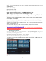
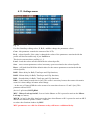
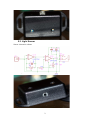
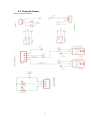
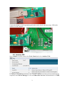
GVI DSLR RC V3 User Manual Table of Contents WIRED REMOTE CONTROL FOR DIGITAL CAMERA........................................................................................2 1. WARNINGS AND LICENSE AGREEMENT ......................................................................................................................2 1.1.1 THE SOFTWARE AND HARDWARE IS PROVIDED "AS IS", WITHOUT WARRANTY OF ANY KIND, EXPRESS OR IMPLIED, INCLUDING BUT NOT LIMITED TO THE WARRANTIES OF MERCHANTABILITY, FITNESS FOR A PARTICULAR PURPOSE AND NONINFRINGEMENT. IN NO EVENT SHALL THE AUTHORS OR COPYRIGHT HOLDERS BE LIABLE FOR ANY CLAIM, DAMAGES OR OTHER LIABILITY, WHETHER IN AN ACTION OF CONTRACT, TORT OR OTHERWISE, ARISING FROM, OUT OF OR IN CONNECTION WITH THE SOFTWARE OR THE USE OR OTHER DEALINGS IN THE SOFTWARE.................................................................................................................2 2. DEVICE OVERVIEW......................................................................................................................................................3 3. BATTERY CHANGING AND PROGRAMMING DONGLE....................................................................................................5 4. OPERATION..................................................................................................................................................................7 4.1. MANUAL MODE.......................................................................................................................................................8 4.2. BULB MODE.............................................................................................................................................................9 4.3. TIME LAPSE MODE.................................................................................................................................................10 WIRED REMOTE CONTROL FOR DIGITAL CAMERA TIME LAPSE VIDEO.......................................................................10 4.4 CLIP MENU..............................................................................................................................................................11 4.5. TRIGGERED MODE..................................................................................................................................................12 4.6 DARKROOM MENU..................................................................................................................................................13 4.7 LIGHTNING MODE...................................................................................................................................................15 4.8. HDR MODE............................................................................................................................................................15 4.9. BULLET MODE.......................................................................................................................................................16 4.10. DROPS MODE.......................................................................................................................................................17 4.11. SETTINGS MENU...................................................................................................................................................18 5. SENSORS.....................................................................................................................................................................19 5.1. SOUND SENSOR......................................................................................................................................................19 5.2. LIGHT SENSOR........................................................................................................................................................20 5.3. PROJECTILE SENSOR...............................................................................................................................................21 5.4. DRIPPER DEVICE.....................................................................................................................................................23 6. FIRMWARE................................................................................................................................................................24 6.1. INSTALL ARDUINO IDE..........................................................................................................................................24 6.2. INSTALL S65DISPLAY LIBRARY.............................................................................................................................24 6.3. CHECK THE LCD TYPE...........................................................................................................................................24 6.4. PROGRAMMING DONGLE........................................................................................................................................24 6.5. ARDUINO IDE........................................................................................................................................................25 7. DOWNLOADS............................................................................................................................................................27 8. UPDATES....................................................................................................................................................................28 9. VIDEO DEMO.............................................................................................................................................................29 1 Wired Remote Control for Digital Camera 1. Warnings and license agreement I have successfully used the sound, light and projectile (only in gravity mode – I don’t have an air gun) sensors with the Canon EOS. If you have a digital camera made by another manufacturer, check the remote control specifications carefully. If you are using a LASER pointer please make sure you read the laser warnings on your laser device, they can be harmful. Never point the laser at anyone and never look directly at the laser beam, it can permanently damage your sight. If you are using a pellet gun be careful where you are pointing it, make sure that the pellet can be stopped by a hard wall and the most important make sure that nobody will stand in front of the gun. 1.1.1 THE SOFTWARE AND HARDWARE IS PROVIDED "AS IS", WITHOUT WARRANTY OF ANY KIND, EXPRESS OR IMPLIED, INCLUDING BUT NOT LIMITED TO THE WARRANTIES OF MERCHANTABILITY, FITNESS FOR A PARTICULAR PURPOSE AND NONINFRINGEMENT. IN NO EVENT SHALL THE AUTHORS OR COPYRIGHT HOLDERS BE LIABLE FOR ANY CLAIM, DAMAGES OR OTHER LIABILITY, WHETHER IN AN ACTION OF CONTRACT, TORT OR OTHERWISE, ARISING FROM, OUT OF OR IN CONNECTION WITH THE SOFTWARE OR THE USE OR OTHER DEALINGS IN THE SOFTWARE. The hardware and software for this project are shared under the Creative Commons Attribution NonCommercial 3.0 License. For this remote I use the following software and hardware schematics with the permission of the authors: - Display driver – a modified version of the S65-Shield for Arduino from Stephan Watterott. In this case I remove some functions from the driver that I don’t use but I also added new cool functions like contrast, display on/off, scroll, display inverting, image from header file, gradient fill, digits. At this moment I fully support only LS020 an L2F50 lcd’s, the LPH88 will need more work. - Drops and Bullet menus – are inspired by Camera Axe project made by Maurice Ribble who also gives me the permission to build no more than 20 Projectile sensors with the condition that all support for hardware and software is made by me. 2 2. Device overview GVI DSLR RC is a remote control for DSLR cameras or any other camera that has a wire remote control port. The main purpose of this device is “freezing” of fast motion objects in a picture (also known as High Speed Photography), that can give you some pretty special photographic effects. High Speed Photography is used in sports, physics and more. The remote control has four input/output stereo female jack connectors, two of them are used to control cameras, flashes or other devices connected to the remote and two of them are use to read data from sensors like sound, light, projectile and other type. Fig. 1 On this device D1 is always a camera and D2 can be: None, Camera, Flash or Split. I will explain later each mode. The 9V connector is used to power the remote using a 7-9V DC power adapter. Warning: Use only 7-9V DC power adapter with max. 700mA output. Remove the batteries from the remote when using 7-9V DC power adapter. Using this power connector will not charge the batteries. When using the USB programming dongle make sure that the power switch is in OFF (0 – see Fig. 3) position. In this case the remote is powered via USB. To navigate through the remote menus I use 6 push buttons shown in the picture below. 3 Fig. 2 Key Functions M Starts and stops the action of the current menu S Select a menu item/Edit value of a menu item U Move’s Up/Increase value with 20 D Move’s Down/ Increase value with 1 L Move’s Left/Decrease value with 1 R Move’s Right/Decrease value with 20 To power up the device use the switch located on top of the remote. Fig. 3 4 3. Battery changing and programming dongle When your batteries power is low you have to change/recharge them. The GVI DSLR RC V3 is powered by 6 AA batteries 1.2-1.5V each. To open the case you will need a small screwdriver to remove the screw plastic caps and also to remove the four screws located on the back of the case at each corner (see Fig. 4). Fig. 4 After you remove all four screws and gently pull up the side of the case with the LCD. Warning: If you remove the battery connector from the board, when reconnecting make sure that the red wire from battery holder is matched with the “+” pin of the Battery connector on the board. If you remove the power switch cable, when reconnecting to OnOff connector on the board there is nothing to check. If you are the happy owner of an Arduino Duemilanove or Uno you can remove the ATMega 328 chip and program it on these boards, if not you will need an USB cable and the programming dongle connected as shown in Fig. 5. 5 Fig. 5 6 4. Operation The GVI DSLR RC V3 has ten operation modes each located in the general menu (Desktop) item and a Settings menu. The Desktop is shown in Fig. 6 Fig. 6 Menu Item Description Manual The devices connected to the remote are controlled by pressing U, D, L, R keys. Bulb Automatic control to take long exposure pictures. Time Lapse Automatic control to take a series of pictures. Clip Triggered This menu is derived from Time Lapse The devices connected are controlled by sensors. DarkRoom Lightning HDR High speed mode to use with camera Bulb and one/two flash devices High Speed mode dedicated to storm lighting photography High Dynamic Range. Bullet Photography of high speed objects. Drops Settings Liquid drops photography. General setting of the remote. 7 4.1. Manual Mode This mode is used to trigger the devices connected to the remote by pressing the control keys. Use M key to Start/Stop this mode, S to Start/Stop editing values, U, D, L, and R to change the parameters values. Key Action U Device 1 Focus – will be On until D key will be pressed D Device 1 Shutter L Device 2 Focus – if Mode is set to Came then will be kept pressed until R key is pressed R Device 2 Shutter - if Mode is set to Came Fig. 7 In any mode D1 jack connector is a camera, so the Mode setting is referring to D2 as follow: Mode None – no device is connected to D2; Mode Came – a camera is connected to D2; Mode Flas – a flash is connected to D2 – Only Shutter pin is used (see Fig. 7); Mode Spli – a camera is connected to D2 – Focus pin is On follow by a delay between 0 and 999 [ms] D2ST (Device2 Split Time) followed by Shutter pin On. In this case you can connect for example two flashes to the remote control and trigger them individually. Seqv On/Off – if sequence in On then D2 is automatically controlled by the Mode setting at a delay SDel between 0 and 9999 [ms] after D key is pressed. 8 Fig. 8 4.2. Bulb Mode The term bulb is a reference to old-style pneumatically actuated shutters; squeezing an air bulb would open the shutter and releasing the bulb would close it. The bulb setting is used on some cameras, including some point-and-shoot cameras, to obtain shutter speeds slower than the maximum offered by the camera otherwise. Because of the risk of camera movement, the camera is most often mounted on a tripod for the duration of the exposure. While it's generally possible to use the shutter release button on the camera itself, a cable release or electronic remote is often used to further eliminate the risk of shaking the camera during the long exposure. The cable releases generally include a locking feature to eliminate the need to keep the button or plunger depressed during extremely long exposures. The bulb setting is useful for the following types of photographic subjects: - fireworks at night; - the night sky and celestial objects (see astrophotography); - lightning; - streets at night (creating streaks from moving cars). This is the mode dedicated to long exposure photography inside an infinite loop that will stop only if you press M key (only after you’ve started using the same key). Use S to Start/Stop editing values, U, D, L, and R to change the parameters values. Don’t forget to put your camera in Bulb mode for this feature to work. Fig. 9 9 In this mode D1 must be a camera and D2 can be Came, Flas or Spli. In D2 case the timer starts when the D1 shutter is On (exposure begins). In Fig. 9 with yellow is the time to wait before starting the function this time is set in Settings Menu. ExpT – is the bulb exposure time in [s] is shown in red. Proc - is the time needed for camera to process the picture (or can be use as a delay time) [s]; Mode - is the device 2 mode - Came, Flas, Spli. D2ST - if Mode is set to Spli then D2ST is the delay in [ms] between D2 Shutter pin and D2 Focus pin. Seqv - if set to On then the D2 is auto controlled and triggerd after SDel in [ms] after D1 is triggered. This mode can be delayed (programmed to start after a predefined time) using DelH, DelM and DelS parameters from Settings Menu. 4.3. Time Lapse Mode Time-lapse photography is a cinematography technique whereby the frequency at which film frames are captured (the frame rate) is much lower than that which will be used to play the sequence back. Time-lapse lets you see the natural progression of time, while not having to wait through the actual length of it… so you could watch the sunset (at least, yesterday’s sunset) as you always wanted to, without staying up late to do so. Photographing the night sky is extremely rewarding because you often get views of things that your own eyes either can't see, or you don't think to look for them. When seeing photos of stars, star trails, or other night images, people are often surprised by the unreal—or surreal—colors. They often think these photos are either fake or manipulated. Wired Remote Control for Digital Camera Time Lapse Video Fig. 10 1 Use M key to Start/Stop this mode, S to Start/Stop editing values, U, D, L, and R to change the parameters values. In Fig. 10 with yellow (right side) is the time to wait before starting the function this time is set in Settings Menu. Hrs – Hour’s interval; Min – Minutes interval; Sec – Seconds interval; Wake – Wakeup interval - activates camera focus to get it out from Stand By 0-59[s] one or two seconds will do the job for most cameras; Pics – Number of pictures to take; UseB – If On will use bulb mode for each picture (Don’t forget to put your camera in Bulb mode for this feature to work); Following are valid only if UseB is On (see 4.2 Bulb Mode) ExpT – Exposure time [s]; Proc - is the time needed for camera to process the picture (or can be use as a delay time) [s]; Mode – D2 mode None, Came, Flas and Spli; D2ST – if Mode is Spli this is Split time in [ms]; Seqv – Activates D2 after SDel [ms]; SDel – Sequence delay in [ms]. Example of simple Time Lapse Time Lapse in combination with Bulb function will give you Star Trails Photography This mode can be delayed (programmed to start after a predefined time) using DelH, DelM and DelS parameters from Settings Menu. 4.4 Clip Menu Fig. 11 1 In Fig. 11 with yellow (right side) is the time to wait before starting the function this time is set in Settings Menu. CLen - Clip length [s]; FPS - Frames per second; FInt - Frames interval [s]; HDR - On/Off. If On this is usefull to create HDR TimeLapse Clips; Wake - Wake [s] up the camera before the shooting with "n" seconds. To use the HDR make sure that you set the Automatic Exposure Bracketing (AEB) before. To give you a little more control in Automatic Exposure Bracketing mode you can use it ether in Aperture Priority Mode or Shutter Priority Mode. Using AEB in Aperture Priority mode will all you to choose the aperture you want for the shot and telling the camera to make the variations in shots by varying shutter speed. Alternatively using AEB in shutter priority mode will keep the shutter speed at the speed you select and tell the camera to vary the exposure by changing the aperture in your shots. Here is an example of HDR Time Lapse Clip This mode can be delayed (programmed to start after a predefined time) using DelH, DelM and DelS parameters from Settings Menu. 4.5. Triggered Mode Freezing fast motion objects in a picture (also known as High Speed Photography), can give you some pretty special photographic effects. High Speed Photography is used in sports, physics and more. This is the first mode dedicated to high speed photography. Use M key to Start/Stop this mode, S to Start/Stop editing values, U, D, L, and R to change the parameters values. Fig. 12 1 Sensor 1 power and sensor 2 power parameters are set by D1By and D2By. S1T@ - Device controlled by sensor 1 will be triggered when the value read by sensor is High (higher) or Low (lower) than S1TV; S1TV – Sensor 1 threshold value; D1By – D1 is triggered by Sen1 (Sensor 1), Sen2 (Sensor 2), S1|2 (Sensor 1 OR Sensor 2), S1&2 (Sensor 1 AND Sensor 2); D1De – D1 delay in [ms] – is the delay between the moment when the sensor assigned to D1 meets the trigger condition and the moment when the D1 is triggered. D1Cy – is the cycle time in [ms] of D1 – is the time to wait between triggers even if the conditions are met (to avoid successive triggers). Mode – D2 mode can be None, Came, Flas or Spli; S2T@ - Device controlled by sensor 2 will be triggered when the value read by sensor is High (higher) or Low (lower) than S2TV; S2TV – Sensor 2 threshold value; D2By – D2 is triggered by Sen1 (Sensor 1), Sen2 (Sensor 2), S1|2 (Sensor 1 OR Sensor 2), S1&2 (Sensor 1 AND Sensor 2); D2De – D2 delay in [ms] – is the delay between the moment when the sensor assigned to D2 meets the trigger condition and the moment when the D2 is triggered. D2Cy – is the cycle time in [ms] of D2 – is the time to wait between triggers even if the conditions are met (to avoid successive triggers). D2ST – D2 Split Time [ms] if D2 Mode is set to Spli. S1 and S2 values from the bottom of the screen are readings of the sensors to see the evolution of the event monitored by sensors. Examples can be seen here 4.6 DarkRoom menu This is very useful when you need to take pictures of high speed events. You will have to use a dark room, set the camera to Bulb and connect a flash or two to D2 jack connector. In this mode Device 1 (Camera) Focus And Shutter are on until the condition to trigger Device 2 are met, after the flash is triggered the function will end and you need to press M key to start it again. Use M key to Start/Stop this mode, S to Start/Stop editing values, U, D, L, and R to change the parameters values. 1 Fig. 13 Sensor 1 power and sensor 2 power parameters are set by D1By and D2By. S1T@ - Device controlled by sensor 1 will be triggered when the value read by sensor is High (higher) or Low (lower) than S1TV; S1TV – Sensor 1 threshold value; Mode – D2 mode can be None, Came, Flas or Spli. Use only Flas or Spli in this mode. S2T@ - Device controlled by sensor 2 will be triggered when the value read by sensor is High (higher) or Low (lower) than S2TV; S2TV – Sensor 2 threshold value; D2By – D2 is triggered by Sen1 (Sensor 1), Sen2 (Sensor 2), S1|2 (Sensor 1 OR Sensor 2), S1&2 (Sensor 1 AND Sensor 2); D2De – D2 delay in [ms] – is the delay between the moment when the sensor assigned to D2 meets the trigger condition and the moment when the D2 is triggered. D2Cy – is the cycle time in [ms] of D2 – is the time to wait between triggers even if the conditions are met (to avoid successive triggers). D2ST – D2 Split Time [ms] if D2 Mode is set to Spli. S1 and S2 values from the bottom of the screen are readings of the sensors to see the evolution of the event monitored by sensors. 1 4.7 Lightning Mode One of the hardest things to get right in a photograph is the lighting. By using GVI DSLR RC V3 in combination with a light sensor connected to Sensor 1 port this can be easy. In this mode the remote will react only to sudden changes in light intensity and for slow changes the sensor reading is autoadaptive, this means that the sensor reading on the screen will indicate most of the time 0 (the values are updated 4 times/second). Fig. 14 S1TV – Sensor 1 threshold value - try to use values above 40; D1Cy – is the cycle time in [ms] of D1 – is the time to wait between triggers even if the conditions are met (to avoid successive triggers). Keep in mind that if Mirror Lock Up is enable then also the cycle time will be increased. 4.8. HDR Mode In image processing, computer graphics, and photography, high-dynamic-range imaging (HDRI or just HDR) is a set of techniques that allow a greater dynamic range of luminance between the lightest and darkest areas of an image than current standard digital imaging techniques or photographic methods. This wide dynamic range allows HDR images to more accurately represent the range of intensity levels found in real scenes, ranging from direct sunlight to faint starlight. Fig. 15 1 Use M key to Start/Stop this mode, S to Start/Stop editing values, U, D, L, and R to change the parameters values. This function works only if the camera is set to Bulb mode. Exp – Base exposure time [ms] is the exposure time that camera firmware chooses function of aperture and ISO speed, for example 1/250 is 4 [ms], 1/1000 is 1 [ms] this is the minimum exposure time in this mode. Remember aperture and ISO speed choose by camera for the exposure time, because you need to set the parameters in Manual + Bulb. Inc – is the EV increment, 250 is 1/4, 333 is 1/3, 500 is 1/2, 666 is 2/3 and so on until 2000 is 2 EV. Pics – is the number of pictures to be taken, maximum 17; The formula for exposure time is BaseExposure * 2 ^-(IncrementValue/1000). Here are some HDR photos 4.9. Bullet Mode High speed bullet pictures passing through various objects! It is almost impossible to capture a speeding bullet with your eye and the impact the bullet creates is even faster and happens within a blink of an eye. It will be very much interesting to see how the objects look while breaking and shape it takes after hitting with a bullet. Fig. 16 Use M key to Start/Stop this mode, S to Start/Stop editing values, U, D, L, and R to change the parameters values. In this mode you can capture the impact of a pellet with different objects or a free falling object. Dist – is distance to target (impact zone) measured from sensor in [cm]; Grav – if you want to capture free falling objects then set this parameter to On; 1 If more than 4 seconds will pass from the time when the function was started and the first photo gate of the sensor doesn’t detect anything then “S1 Detection failed.” error will be raised and the function will end. If more then 1.5 second will pass from the time when first photogate will detect an object and photo gate 2 will not detect the object then “S2 Detection failed.” Error will be raised and the function will end. If both photo gates are triggered then the speed of the object will be diplayed on the screen. This function was tested by me only in gravity mode and using small balls propelled by air from a small pressure tube. 4.10. Drops Mode One fun digital photography challenge for those with a little time on their hands, particularly on a lazy long weekend as I know many of you are on, is photographing water drops. With the Dripper device used in Drops Menu you can obtain results like those in the following links Water drops collision or Milk Crowns. Fig. 17 Use M key to Start/Stop this mode, S to Start/Stop editing values, U, D, L, and R to change the parameters values. Dr1S – Drop 1 size is the time in [ms] needed to form first drop, long time = big drop; De2D – Drop 2 delay it the time to wait between drop 1 and 2 in [ms]; Dr2S – Drop 2 size is the time in [ms] needed to form first drop, long time = big drop; PicD – Picture delay I the time between drop 2 and the moment when the picture is taken in [ms]. 1 4.11. Settings menu Fig. 18 Use S to Start/Stop editing values, U, D, L, and R to change the parameters values. Cont – this parameter controls the contrast of the LCD; Prof – selected profile, if the value is changed the values of the parameters associated with the profile will become usable only if you Load them. This device can store three profiles 0, 1, 2. Load – loads the values stored in ROM for the selected profile; Save – saves current parameters values in memory space associated to the selected profile; Reset – will load from ROM the default values for the remote parameters associated with the selected profile; DelH - Hours delay for Bulb, TimeLapse and Clip functions; DelM - Minute delay for Bulb, TimeLapse and Clip functions; DelS - Seconds delay for Bulb, TimeLapse and Clip functions; BDel – is the button pressed time in [ms]. This value is necessary because the camera electronics wont feel a short change in button status change – in the case of Canon 450D the value seems to be somewhere between 1.5 and 2 [ms]. This parameter affects D2ST (device 2 split time) D2ST≥BDel. MLU - Mirror Lock-up On/Off, if set to On the Shutter on D1 is pressed to activate the Mirror Lock-up on Camera; MLUD - in [ms] is the delay time between the time when Shutter on D1 is pressed to activate MLU and the time when the picture is taken - it allows to reduce the vibrations induces by MLU. MLU parameters are valid for all menus so they will insert a additional delay. 1 BkLi - Back Light control: 0 = always Off; 1 = always On; 2 = Auto Off after 6 sec. For this parameter to work some hardware changes have to be made(see section 8 Updates). 5. Sensors For this remote control I make three sensors: light, sound and projectile. Each sensor is connected to the remote using a stereo cable - male-male jack of 3.5 mm. Each sensor receives his power (4.5 -5V) through the tip terminal and sends signal to the remote through the ring terminal. 5.1. Sound Sensor Sensor electronic scheme 1 5.2. Light Sensor Sensor electronic scheme 2 5.3. Projectile Sensor Sensor electronic scheme 2 I also make hotshoe adaptor’s to connect a flash to the remote (see picture below). A hot shoe is a mounting point on the top of a camera to attach a flash unit. 2 5.4. Dripper device Sensor electronic scheme With the Dripper device used in Drops Menu you can obtain results like those in the following links Water drops collision or Milk Crowns. 2 6. Firmware To program the “brain” of this remote I use Arduino IDE that can be downloaded from http://www.arduino.cc/en/Main/software. The ATMega 328 CPU found on this remote is flashed with Arduino UNO boot loader, so before starting the firmware update you need to choose the UNO board. 6.1. Install Arduino IDE After you download the Arduino environment, follow the instructions on the Arduino site to install it under your OS (Windows, Linux, Mac). 6.2. Install S65Display library Download the S65Display library from my site and unzip it in the folder ..\arduino-00xx\libraries\ and unzip. 6.3. Check the LCD type On the main board inside the case you will find a label that has written on it LS020 or L2F50. If the label is LS020 then copy from the folder “font” font_8x8.c and font_8x8.h files in S65Display folder. If the label is L2F50 then copy from the folder “font_rt” font_8x8.c and font_8x8.h files in S65Display folder. The L2F50 has a different way of addressing the pixels so for it I had to rotate with 90Deg clockwise and mirror vertically the bits for the fonts in order to keep the load on the CPU low. Also you will need to open and edit the file S65Display.h and o to lines 33-36 in the code. There you will find //Display settings //#define S65_LS020 //#define S65_LPH88 #define S65_L2F50 // means that the line is commented (will not be compiled), so if you have an L2F50 you have to comment/uncomment the line corresponding to your screen. On L2F50 the contrast function doesn't work at this time, work is in progress but i don't know if i will succed. The contrast works now on L2F50. 6.4. Programming dongle If you don’t have an Arduino UNO or Duemilanove (http://grozeaion.com/electronics/arduino/131atmega328p-burning-bootloader.html see how to transform a Duemilanove in to UNO and get more space in ATMega 328 memory) then you will need the programming dongle. 2 Connect the dongle to the Programming pin header on the board and then using a USB cable connect it to the computer. 6.5. Arduino IDE Open Arduino, from the menu select Tools, Board and select Arduino UNO. In Tools go to Serial Port and choose the COM XX (depends on what you have attached to the computer) in the Device Manager is seen as USB Serial Converter and manufacturer is FTDI. 2 Now from File menu choose Open and point to the folder where you unzip the GVI_DSLR_RC_v3 and select GVI_DSLR_RC_v3.pde file then click Open. In your window is shown the code that runs on the remote control. If you have any programming skills then you can play with the code and make adjustments to serve you better, if not leave the code as it is. 2 Click on the Upload button (the arrow pointing to right) and wait for the code to be uploaded into the chip. If you have any trouble or questions please contact me by e-mail (don’t forget to attach some screen shots) with the problem description. 7. Downloads Eagle files (sch and brd): InOut module Light Sensor Projectile Sensor Sound Sensor Main Board USB Dongle Firmware GVI_DSLR_RC_V3R1 GVI_DSLR_RC_V3R2 2 Added delay timer for Bulb, Time Lapse and Clip menus. The delay timer is found in Settings menu and the parameters are DelH 0-99[h], DelM 0-59[min], DelS 0-59[s]. Added Clip menu GVI_DSLR_RC_V3R3 Added Mirror Look Up support Some bugs removed Improved use of RAM memory Removed processing time in Bulb Mode (ROM_BulbProc) Removed HDR Button Delay (ROM_HDRBtnDelay) GVI_DSLR_RC_V3R4 - Skipped (all changes incorporated in V3R5) GVI_DSLR_RC_V3R5 Some bugs removed Improved use of RAM memory (Decrease the size of logo image - download new S65 Display Driver) Re added processing time in Bulb Mode (Proc) Added Back Light Control (BkLi) Recoded battery indicator and buttons. S65 Display Driver Manual Wired Remote Control for Digital Camera Manual 8. Updates Added wiki page http://grozeaion.wikispaces.com/ Added hardware and software support for LCD Back Light. 2 9. Video Demo http://www.youtube.com/watch?v=55V1PW0Urew 2