1
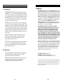
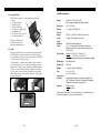
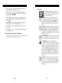
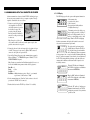
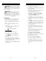
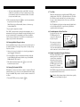
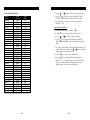
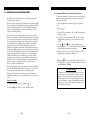
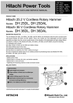
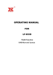
OI908L
NOTES
TABLE
OF
CONTENTS
1.0 Introduction . . . . . . . . . . . . . . . . . . . . . . . . . . . . . . . . . . . . . . . .
2
2.0 Precautions . . . . . . . . . . . . . . . . . . . . . . . . . . . . . . . . . . . . . . . .
2
3.0 Overview of Gauge. . . . . . . . . . . . . . . . . . . . . . . . . . . . . . . . . .
3
3.1 Gauge
3.6 Display Backlight
3.2 Contents of Kit
3.7 Probe Zero Plate
3.3 Probe
3.8 Connector Probe & Test Plate
3.4 Keypad
3.9 Battery Compartment (Battery Replacement)
3.5 LCD Display
4.0 Getting Started . . . . . . . . . . . . . . . . . . . . . . . . . . . . . . . . . . . . .
10
4.1 Connecting The Probe 4.4 Changing Units — inches to mm
4.2 Turn On The Power
4.5 Checking Calibration with the Test Plate
4.3 “Zeroing” The Probe 4.6 Preparation of the Surface
5.0 Quick Start Instructions — Steel Thickness . . . . . . . . . . . .
6.0 Calibration For Measuring Thckness
Of Materials Other Than Steel . . . . . . . . . . . . . . . . . . . . . . . .
6.1 Acoustic Velocity Table
6.2 Changing Calibration — Acoustic Velocity is Known
6.3 Changing Calibration — Acoustic Velocity is Not Known
6.4 Performing a 2-Point Calibration
– 36 –
13
15
7.0 Description of Measuring Modes . . . . . . . . . . . . . . . . . . . . .
20
8.0 Alarm & Beeper Modes . . . . . . . . . . . . . . . . . . . . . . . . . . . . . .
22
9.0 Measuring Procedure . . . . . . . . . . . . . . . . . . . . . . . . . . . . . . .
9.1 General Notes On Measurements
9.2 Measurements Of Pipes Or Cylindrical Parts
9.3 Measurements On Materials At High Temperatures
24
10.0 Using the Built-in Data Logger . . . . . . . . . . . . . . . . . . . . . . .
10.1 Storing Data
10.2 Clearing Individual Storage Locations
10.3 Clearing the Contents of a File
10.4 Clearing Data From All Files Simultaneously
27
11.0 Downloading Data To A Computer Or Printer. . . . . . . . . . .
11.1 Download Data to a Computer
11.2 Download Data to a Printer
11.3 Download Data to Check•Line P-25DL Printer
30
12.0 Specifications . . . . . . . . . . . . . . . . . . . . . . . . . . . . . . . . . . . . . .
33
13.0 Material Safety Data Sheet (MSDS). . . . . . . . . . . . . . . . . . . .
34
14.0 Warranty . . . . . . . . . . . . . . . . . . . . . . . . . . . . . . . . . . . . . . . . . .
35
–1–
14.0 WARRANTY
1.0 INTRODUCTION
The CHECK•LINE® TI-25DL Ultrasonic Thickness Gauge measures the
wall thickness of metals, glass, ceramics and many rigid plastics. This gauge
uses the “pulse-echo” principle of ultrasonic testing where a short ultrasonic
signal is transmitted from the probe. The signal travels through the measurement sample until it is reflected back towards the probe from the back side
of the material. The elapsed time for the complete cycle is measured and
converted to an accurate thickness reading.
The TI-25DL can be used to measure the extent of corrosion on the opposite, inaccessible side of the wall by using the “Subtractive Method.” When
the thickness of the original wall is known, subtracting the thickness reading
obtained from the gauge will determine the extent of corrosion at the point
of probe placement. If the original wall thickness is not known, test readings
should be made along a grid of equally-spaced points to obtain a profile of
the thickness readings. The smallest thickness reading will locate the area of
greatest concern.
The TI-25DL is factory-set to measure steel. The gauge can be easily
adjusted for accurate thickness readings on other materials. Refer to
Sections 6.0 through 6.3. To change the measuring units from inch
(factory setting) to mm refer to Section 4.4.
The TI-25DL incorporates a built-in data logging system which permits the
end user to store up to 1000 measurements in 10 separate batches. The
stored data can be printed or downloaded to a PC using the supplied Data
Transfer Program and serial cable.
2.0 PRECAUTIONS
Do not use the standard probe in applications where material temperatures
exceed 200 °F (100 °C) as the probe will be damaged. Special High
Temperature Probes should be used. Consult factory.
Keep the gauge free of dust (especially metal powders, carbon, etc.) as they
will damage the gauge. Use a damp cloth to clean the gauge after use.
DO NOT USE CHECMICAL SOLVENTS OF ANY KIND.
–2–
ELECTROMATIC Equipment Co., Inc. (ELECTROMATIC) warrants to the
original purchaser that this product is of merchantable quality and confirms
in kind and quality with the descriptions and specifications thereof. Product
failure or malfunction arising out of any defect in workmanship or material
in the product existing at the time of delivery thereof which manifests itself
within one year from the sale of such product, shall be remedied by repair
or replacement of such product, at ELECTROMATIC’s option, except where
unauthorized repair, disassembly, tampering, abuse or misapplication has
taken place, as determined by ELECTROMATIC. All returns for
warranty or non-warranty repairs and/or replacement must be authorized by
ELECTROMATIC, in advance, with all repacking and shipping expenses
to the address below to be borne by the purchaser.
THE FOREGOING WARRANTY IS IN LIEU OF ALL OTHER
WARRANTIES, EXPRESSED OR IMPLIED, INCLUDING BUT NOT
LIMITED TO, THE WARRANTY OF MERCHANTABILITY AND
FITNESS FOR ANY PARTICULAR PURPOSE OR APPLICATION.
ELECTROMATIC SHALL NOT BE RESPONSIBLE NOR LIABLE
FOR ANY CONSEQUENTIAL DAMAGE, OF ANY KIND OR NATURE,
RESULTING FROM THE USE OF SUPPLIED EQUIPMENT, WHETHER
SUCH DAMAGE OCCURS OR IS DISCOVERED BEFORE, UPON OR
AFTER REPLACEMENT OR REPAIR, AND WHETHER OR NOT SUCH
DAMAGE IS CAUSED BY MANUFACTURER’S OR SUPPLIER’S
NEGLIGENCE WITHIN ONE YEAR FROM INVOICE DATE.
Some State jurisdictions or States do not allow the exclusion or limitation of
incidental or consequential damages, so the above limitation may not apply
to you. The duration of any implied warranty, including, without limitation,
fitness for any particular purpose and merchantability with respect to this
product, is limited to the duration of the foregoing warranty. Some states
do not allow limitations on how long an implied warranty lasts but, not
withstanding, this warranty, in the absence of such limitations, shall
extend for one year from the date of invoice.
ELECTROMACTIC Equipment Co., Inc.
600 Oakland Ave. Cedarhurst, NY 11516—USA
Tel: 1-800-645-4330/ Tel: 516-295-4300/ Fax: 516-295-4399
Every precaution has been taken in the preparation of this manual. Electromatic Equipment Co.,
Inc., assumes no responsibility for errors or omissions. Neither is any liability assumed for damages resulting from the use of information contained herein. Any brand or product names mentioned herein are used for identification purposes only, and are trademarks or registered trademarks of their respective holders.
– 35 –
13.0 MATERIAL SAFETY DATA SHEET (MSDS)
3.0 OVERVIEW OF GAUGE
Section 1— Product Identification
Product Name: TI-25DL
Manufacturer: Electromatic Equpt. Co.
Generic Name: Ultrasonic Couplant
NFPA Hazardous Materials Identification System (est)
Health 0
Flammability 0 Reactivity 0
3.1 Gauge
Section 2— Hazardous Ingredients
This material does not contain any ingredients having known health hazards in concentrations
greater than 1%. This material does not contain any known or suspected carcinogens.
Section 3 — Physical Data (nominal)
Boiling Point: >220°F
Vapor Pressure: N/A
Specific Gravity: >1.0Z
pH: 7.35 – 7.9
Vapor Density: N/A
Freezing Point: <20°F
Evaporation Rate: N/A
Solubility in Water: complete
Acoustic Imp.: 1.726 x 10⁶
Appearance and Odor: water white, opaque gel; bland odor
Section 4 — Fire and Explosive Hazard Data
Flash Point: none Upper Exposure Limit: none
Special Fire Fighting Procedures: N/A
Unusual Fire and Explosion Hazards: none
Probe Zero Test Plate
(battery compartment cover)
Probe
Receptacles
Lower Exposure Limit: none
Extinguishing media: N/A
Section 5 — Reactive Data
Stability: Stable
Conditions to Avoid: none
Incompatibility (Materials to Avoid): none known
Hazardous Polymerization: will not occur
Hazardous Decomposition or Byproducts: none known
Section 6 —- Health Hazard and First Aid Data
Routes of Entry1:
Skin: not likely Ingestion: not normally
Effects of Overexposure:
Acute: May cause temporary eye irritation
Backlit LCD
Display
Red LED
Green LED
Eyes: not normally
Membrane
Keypad
Inhalation: no
Chronic: none expected
First Aid Procedures:
Skin: Remove with water if desired.
Eyes: Flush with water for 15 minutes.
Ingestion: For large quantities, induce vomiting and call a physician
Inhalation: N/A
Section 7 - Storage and Handling Information
Precautions to be taken in handling and storage: Store between 20 °F and 120 °F. Spills are
slippery and should be cleaned up immediately. Steps to be taken in case material is released or
spilled: Pick up excess for disposal. Clean with water. Waste disposal method: Dispose of in
accordance with federal, state, and local regulations.
Bottom of Gauge
Section 8 — Control Measures
Respiratory Protection: not required
Ventilation: not required
Protective Gloves: on individuals demonstrating sensitivity to TI-25
Eye Protection: as required by working conditions
Other Protective Equipment: not required
1. TI-25DL contains only food grade and cosmetic grade ingredients.
– 34 –
Serial Output
Port
Probe
–3–
3.2 Contents Of Kit
The TI-25DL is supplied as a complete kit with the following:
a. Gauge
a
g
b. Two (2) AA batteries
(installed in gauge)
c. Probe/cable assembly
d. 4 oz. Bottle of coupling fluid
e. Serial Output cable
f. Data Trasfer software program
g. Foam-filled carrying case
c
Not shown: NIST-traceable
calibration certificate and
Operating instruction manual
12.0 SPECIFICATIONS
d
f
e
3.3 Probe
The probe transmits and receives the ultrasonic sound waves which
the TI-25DL uses to calculate the thickness of the material being
measured. The probe must be used correctly in order for the TI-25DL
to produce accurate and reliable results.
A small amount of “coupling” fluid, commonly called “couplant” is
used to insure that there are no air gaps between the probe and the
material surface. Grasp the probe by the knurled aluminum housing
and place it on top of the material surface. Apply moderate pressure
to the top surface of the probe with your thumb (A) or index finger
(B) to stabilize the probe and to keep the wearface seated flat against
the measurement surface.
A
B
Range*
0.025–6.00" (0.60–150.0 mm)
Other ranges available with optional probes.
Resolution
.001" (0.01 mm)
Display
4 1⁄ 2 -Digit, 0.5" Backlit LCD
Velocity
Range
0.0787 – 0.3937 in./µs (2000–10,000 m/sec.)
Probe
7.5 MHz, 0.25" Diameter (6.35 mm)
Probe
Wearface
PEEK (Polyethylethylkeytone)
Cable
4 ft. (1.2 m) waterproof cable with non-polarized,
quick-disconnect connectors. Optional lengths up to
100 ft. (30 m).
Temp. Limits
Ambient: –20 to 120 °F (–30 to 50 °C)
Material:
0 to 200 °F (–20 to 100 °C)
Special high temperature probes are optionally available.
Battery Type
Two AA batteries
Battery Life
200 hours
Weight
10 ounces (280 g), with battery
Size
2.5 x 4.5 x 1.25"
(64 x 114 x 32 mm)
Accessories
Included
Warranty
Probe/cable assembly. 4oz. bottle of coupling fluid,
NIST Calibration Certificate, 2 AA batteries, operating
instructions, hard-plastic carrying case.
Gauge: 5 years
Probe: 90 days
*Measuring Range indicated is for steel. Actual range for other materials will vary
based upon the material’s sonic velocity and attenuation.
Probe
Wearface
–4–
– 33 –
3. Press the
key to enter the file setup. The currently selected file
number will be displayed (F-01, F-02 .... F-10).
3.4 Keypad
CAL
MODE
4. Press the
key to select the currently displayed File Number for
printing or press the
or
keys to index the File Number to the
desired File Number to be printed.
5. Press the
key to select the desired file for printing. The display
will alternately flash “FILE” and “F-XX” (where “XX” is the File
Number 01, 02 ..10).
MEM
SEND
PROBE
ZERO
MODE
6. Press the
key once. The display will alternately flash “Prnt” and
“F-XX” (where “XX” is the File Number 01, 02 ..10).
7. Press the
key to print a report using the data stored in the selected
File Number.
MEM
8. Press the
key at any time to exit the data logging mode and return
to measurement mode.
11.3 Download Data to Check•Line P-25DL Printer
Perform all of the steps detailed above (Sec. 11.2, steps 1–8), except in
step 6, instead of selecting “Prnt,” select “LISt.”
PROBE
ZERO
CLR
ON
OFF
The TI-25DL is supplied with a membrane keypad
mounted on the front of the instrument body. It consists of nine (9) keys, each performing one or more
functions as described below.
The MODE key is used to toggle through the various features and settings including alarm mode, beeper, back light,
units, scan mode and differential mode. The MODE key is
used in conjunction with the UP & DOWN ARROW and
SEND keys to enable and disable the various features and
settings.
The MEM key enables/disables the data logging features of
the TI-25DL. This key is used in conjunction with the UP &
DOWN ARROW keys as well as the SEND and CLR keys.
These keys in different combinations control all of the data
logging functions. For additional information, refer to Section
10.0, Using the Data Logger.
The PROBE ZERO key is used to “zero” the probe in a similar way as a micrometer is “zeroed” before use. If the tool is
not zeroed correctly, the measurements will not be accurate.
The UP ARROW key has three (3) functions. In the
Calibration mode, this key is to increase numeric values on
the display. An "auto-repeat" function is built in, so that when
the key is pressed and held down, the numeric values will
change at an increasing rate. When the Mode function is activated, the UP ARROW key scrolls through the various features and settings of the TI-25DL. When the Memory mode
is activated, the UP ARROW key scrolls through the various
batches, storage locations and functions of the data logger.
For additional information, refer to Section 10.0, Using the
Data Logger.
SEND
– 32 –
The SEND key is used to store measured values to internal
storage locations or downloading stored data to external
devices such as a serial printer or computer. The SEND key
is also used to select data logging functions in the TI-25DL.
For additional information, refer to Section 10.0, Using the
Data Logger.
–5–
CAL
CLR
ON
OFF
The DOWN ARROW key has three (3) functions. In the
Calibration mode, this key is to decrease numeric values on
the display. An "auto-repeat" function is built in, so that when
the key is pressed and held down, the numeric values will
change at an increasing rate. When the Mode function is activated, the DOWN ARROW key scrolls through the various
features and settings of the TI-25DL. When the Memory
mode is activated, the DOWN ARROW key scrolls through
the various batches, storage locations and functions of the
data logger. For additional information, refer to Section 10.0,
Using the Data Logger.
11.1 Download Data to a Computer
Once the TI-25DL is connected to the computer and the communications
program is running, the data can be downloaded by performing the following steps:
The CAL key is used to enter and exit the Tl-25DL’s two
Calibration modes. The Acoustic Velocity Calibration mode is
used to adjust the acoustic velocity for the material to be
measured. The Measurement Calibration mode is used to
increase or decrease the displayed thickness reading to calibrate to a known thickness value.
3. Press the
or
“Send” and “ALL”.
The CLR key is used exclusively with the data logging
feature to clear the contents of a batch or delete individual
measurement values. The CLR key is also used to store an
"obstruct" (ObSt) to an individual storage location. The
"ObSt" symbol would indicate that the user was unable to
take a reading at that specific location. For additional information, refer to Section 10.0, Using the Data Logger.
The ON/OFF key is used to turn the power on as well as
turning the power off. If the Tl-25DL is idle for five (5)
minutes the gauge will automatically power off.
1. Turn on the TI-25DL power by pressing the
2. Press the
key.
key to activate the data logger.
The display will alternately flash “FILE” and the “F-XX” (where XX is
the currently selected File Number). Please note that there are 10
separate files (F-01 through F-10)
key twice until the display alternately flashes
4. Press the
key to download (send) the stored data from all of the
Files to the computer.
5. Press the
key to exit the data logging mode and return to
measurement mode.
11.2 Downloading Data to a Printer
In addition to the possibility of downloading the stored data to a PC, the
TI-25DL can print a “pre-formatted” report on a serial printer. This report
can also be sent to a PC and then printed. The user first must select a
specific File Number (F-01 ... F10) for printing.
Set the communications parameters for the printer to:
Data Bits =
Parity
=
Stop Bits =
Baud Rate =
8
None
1
1200
To print the pre-formatted report to a serial printer or PC perform the
following steps.
1. Turn on the TI-25DL power by pressing the
2. Press the
key.
key to activate the data logger.
The display will alternately flash “FILE” and the “F-XX” (where XX
is the currently selected File Number). Please note that there are 10
separate files (F-01 through F-10)
–6–
– 31 –
11.0 DOWNLOADING DATA TO A COMPUTER OR PRINTER
After measurements have been stored in the TI-25DL’s built-in data logger,
the user may want to transfer the data to a computer or printer. The steps
required to download the data are as follows:
1. Connect one end of the serial output
cable (supplied) to the TI-25DL
serial output connector located on
the bottom of the gauge. The
protective plastic plug inserted
into this connector should first be
removed. Store this protective plug
for future use.
Note: Line up the red dot on the
cable connector with the red dot on the serial output receptacle, then
push the connector into the receptacle.
2. Connect the other end of the serial output cable to the 9-pin serial port
of the PC. If necessary, the user can use a DB9-to-DB25 converter to
connect it to the 25-pin serial port on the PC.
3. Start the Data Transfer Program or other communications program (i.e.
Microsoft Windows™ 3.1 TERMINAL Program or Windows™ 95 / 98
HYPER TERMINAL Program).
Note: If using a program other than DataComm (supplied), be sure to set
the Set the communications parameters in the software program to:
Data Bits =
Parity
=
Stop Bits =
Baud Rate =
8
None
1
9600 (when trying to print a “Report”— pre-formatted
report format, set the baud rate to 1200)
4. Set the communications port (“Com Port”) in the software to the serial
port where the TI-25DL cable is connected.
3.5 LCD Display
The LCD Display provides the operator with important information.
+ INMM/µs
1.8.8.8.8
• Measurement values
• Acoustic velocity values
• Units of measure
• Bar graph signal stability indicator
• Configuration messages
The numeric portion of the display consists of 4-digits preceded by a leading "1",
and is used to display numeric values, as
well as occasional simple words, to indicate the status of various settings. When the TI-25DL is displaying
thickness measurements, the display will retain the last measured
value, until a new measurement is performed.
+ INMM/µs
1.8.8.8.8
The eight vertical bars shown form the
Stability Indicator. When the TI-25DL is
idle, only the left-most bar and underline
will be illuminated. When a measurement
is being performed, six or seven bars should be illuminated indicating
that it is a stable measurement. If fewer than five bars are illuminated,
the TI-25DL is having difficulty obtaining a stable and reliable measurement and the thickness value shown should be ignored, as it is
most likely erroneous.
+ INMM/µs
1.8.8.8.8
+ INMM/µs
1.8.8.8.8
+ INMM/µs
1.8.8.8.8
When the “IN” indicator is illuminated,
the TI-25DL is displaying a wall thickness
measurement in INCH units.
When the “MM” indicator is illuminated,
the TI-25DL is displaying a wall thickness
measurement in MM units.
5. Download the data from the TI-25DL (see Section 11.1 for details).
+ INMM/µs
1.8.8.8.8
– 30 –
When the “IN” and the “µs” indicators are
illuminated simultaneously, the TI-25DL
is displaying an acoustic velocity in inches
per microsecond.
–7–
+ INMM/µs
1.8.8.8.8
+ INMM/µs
1.8.8.8.8
When the “M” and the “s” are illuminated
simultaneously, the TI-25DL is displaying
an acoustic velocity in meters per second.
When in Differential Measurement mode,
the measured values will be displayed as
“+” or “-” from a user-set “nominal” value.
The “+” and “-” indicator is located next to
the “IN” units indicator.
3.6 Display Backlight
The TI-25DL is supplied with a user-set Backlight mode. The back
light can be set to operate in any of the following three modes:
1. ON
The backlight is illuminated whenever the power is on.
2. OFF
The backlight is never illuminated (to save battery
power)
3. AUTO The backlight is automatically illuminated each time a
measurement is made.
Note: The factory default setting is “OFF.”
To Change Backlight Mode
1. Turn on the TI-25DL power by pressing the
key.
2. Press the
key to activate the features and settings menu.
3. Press the
display.
or
key until ... "LitE" is shown on the
2. Press the
key to activate the data logger.
The display will alternately flash “FILE” and the “F-XX” (where XX is the
currently selected File Number).
3. Press the
key to enter the file setup. The currently selected File
Number will be displayed (F-01, F-02 .... F-10).
4. Press the
key to select the currently displayed File Number
clearing or press the
or
keys to index the file number to the
desired File Number to be cleared of all stored data.
5. Press the
key to select the file for clearing. The display will
alternately flash “FILE” and “F-XX” (where “XX” is the File Number
01, 02 ..10).
6. Press the
key. The display will alternately flash “F-XX” and “CLr”.
7. Press the
key to clear the contents of this File Number. The display
will show “CLr?” checking to make sure the user wants to clear the
contents of the selected File.
8. Press the
or press the
function.
key to confirm the request to clear (erase) the data
key to abort this action and exit the data logging
Note: The user can press the
key at any point to exit the data
logging function and return to the measurement mode.
10.4 Clearing Data From All Files Simultaneously
If the user would like to clear (erase) the entire contents of the data loggers
memory (all Files) perform the following steps:
1. Turn on the TI-25DL power by pressing the
4. Press the
key to change the currently selected backlight
mode. Each time the SEND key is pressed the backlight mode will
change from "Aut0", to "On" to "OFF".
5. Press the
key to select the current backlight mode and return
to measurement mode.
–8–
2. Immediately press the
3. Press the
or press the
function.
key.
key. The display will show “CLr?
key to confirm the request to clear (erase) the data
key to abort this action and exit the data logging
– 29 –
• An obstruct condition indicated by the symbol “ObSt”. An obstruct
condition is recorded when a user has pre-assigned storage locations
to measurement locations and a measurement could not be obtained
(for any reason) in this location.
6. Take a measurement and press the
key to store the measurement in
the previously-selected storage location.
Note: The data logger will automatically advance to the next storage
location within the file.
7. Repeat step #6 as many times as desired.
If the “FuLL” symbol is shown on the display when attempting to store a
measurement, the data logger is advising the user that the currently-selected
storage location already has a measurement stored. The user should first
clear the storage location (refer to Section 10.2) or select another unused
(empty) storage location for the measurment.
10.2 Clearing Individual Storage Locations
Data in any individual storage location can be cleared (erased) and replaced
by another measurement or left empty. The procedure for clearing a storage
location is as follows:
1. Advance to the storage location that is to be cleared by performing the
steps #1 through #5 in Section 10.1
2. Press the
key to delete the measurement currently stored in this
location. The display will alternately flash the storage location (L001 ...
L100) and then the “CLr” symbol.
3. Take another measurement and press the
location that was just cleared.
key to store it in the
10.3 Clearing The Contents Of A File
When desired, a user may erase (clear) the content of an entire file. This will
permit the end user to store a new series of measurements in this file starting
storage location L001. The procedure to clear the contents of an entire file is
as follows:
1. Turn on the TI-25DL power by pressing the
– 28 –
key.
3.7 Test Plate
When first connecting the probe supplied with the TI-25DL, the user
should perform a “Probe Zero” as described in Section 4.3. The Probe
Zero Test Plate is used for this task. It is located on the top edge of
the gauge as shown in the photo below. It also serves as the battery
compartment cover
Note: The thickness of this plate is not imporatnt, and it should not be
used as a Calibration Test Plate. A precision 4-step Test Block is
optionally available for this purpose.
3.8 Probe Receptacles & Probe Zero Plate
Located on the top edge of the
TI-25DL housing are the
Probe Receptacles
receptacles for the probe and
the probe zero plate.
Probe Zero
Plate
The connectors for the probe
are non-polarized so the connector at the end of the probe
cable can be inserted into this receptacle in either orientation. Make
sure the connector is “well seated” in the receptacle.
3.9 Battery Compartment (Changing The Battery)
The battery compartment is located
Battery Cover
under the probe zero test plate. To
open the battery compartment,
unscrew the probe zero plate by
rotating it counterclockwise. The
TI-25DL operates on two (2) AA
Batteries (1.5 V). If desired,
rechargeable batteries may be used.
The TI-25DL is shipped with the batteries installed. Insert batteries in
the polarity indicated on the rear label.
Note: When the display elements begin to flash off and on repeatedly,
the batteries are low and should be replaced.
–9–
10.0 USING THE BUILT-IN DATA LOGGER
4.0 GETTING STARTED
4.1 Connecting The Probe
Grasp the connector located at the end of the probe cable and carefully
insert the connector plugs into the receptacle located at the top edge of
the gauge. Make sure the connector is fully inserted into the receptacle. The orientation of the plugs does not matter as they are nonpolarized. Refer to Section 3.8 for additional details
4.2 Turn On The Power
Press the
key. All of the LCD Display elements will momentarily
illuminate. The firmware revision will then be momentarily shown
(for factory troubleshooting purposes only). Eventually the display
will show “0.000” (or “0.00” if using metric units), indicating it is
ready for use.
Note: 1. The gauge is turned off by pressing the
key again.
2. The gauge will automatically power off after 5 minutes of
non-use.
3. All settings will be retained in non-volatile memory.
4.3 “Zeroing” The Probe
The Probe Zero Plate is used to “zero” the probe for calibration purposes. Normally, this procedure is required only when the probe is
connected to the instrument for the first time, but since this process
takes less than 10 seconds, we recommend performing the Probe Zero
function occasionally as described below.
1. Check that the probe face (wear surface) is clean and free of debris.
2. Place a small drop of the supplied coupling fluid on the built-in
Probe Zero Plate located on the top of the gauge.
3. Press the probe firmly against the Plate.
4. The Stability Indicator on the LCD display should have six or
seven bars illuminated and a value should be shown in the display.
5. While maintaining probe contact with the Test Plate, press the
key. The display will show “Prb0” while the TI-25DL
calculates its zero point.
Note: The value shown on the display can be recorded and used in the
future to confirm that the gauge is functioning properly.
– 10 –
The TI-25DL incorporates a built-in data logging system that permits the
user to store up to 1000 data points. The stored data is grouped into 10
separate files (“batches”) with each file containing a maximum of 100
values. Each measured value is assigned a unique storage location within
the file. The user may download the stored data to a computer or to a serial
printer.
The end user must first select one of the ten (10) available files to store
measured values. The user normally would perform the following steps:
1.
2.
3.
4.
Select a File Number
Select a Storage Location within the file
Make a measurement
“Send” displayed measured valued to the Storage Location in the File.
Detailed procedures are provided in the following sections.
10.1 Storing Data
1. Turn on the TI-25DL power by pressing the
key.
2. Press the
key to activate the data logger. The display will alternately
flash “FILE” and “F-XX” (where “XX” is the File Number 01, 0...10).
Please note that there are 10 separate files (F-01, F-02 ... F-10)
3. Press the
key to enter the file setup. The currently-selected File
Number will be displayed (F-01, F-02 .... F-10).
4. Press the
key to select the currently displayed File Number or press
the
or
keys to index the File Number. When the desired File
Number is displayed, press the
key to select it.
5. Press the
key to advance to the first Storage Location (L001)
in the selected File. Press the
or
keys to advance to other
Storage Locations within the selected File.
The display will alternately flash the storage location (L-XXX, where
XXX is the storage location 001, 002 ... 100) within the selected File
Number. Each Storage Location can contain one of the following three
things:
• A measurement value that was previously stored
• A clear (empty) location indicated by the symbol “CLr”
– 27 –
9.3 Measurements On Materials At High Temperatures
When it is necessary to measure wall thickness on surfaces that are in
excess of 200 °F (100 °C), special-purpose high temperature probes
should be used. These probes are built using special materials and
techniques that allow them to withstand high temperatures without
damage. Additionally, care must be taken when performing a “Probe
Zero” or “Calibration To Known Thickness” using a High Temperature
probe.
At such elevated temperatures, it is recommended that the user follow
these procedures:
1. Perform a calibration procedure on a sample of known thickness
(refer to Section 6.3) with the material temperature at or near the
temperature that will be encountered during measurement.
2. Remove the probe from the hot surface immediately after a “stable”
reading is displayed. Even though the High Temperature Probes are
constructed using materials which can withstand high temperatures,
the probe can begin to heat up, through thermal expansion and
other effects, adversely affecting the accuracy of the measurement.
Note: The probe can be cooled by submerging it in water.
4.4 Changing Units — inches to mm
The TI-25DL can be set to measure in units of “INCH” or “MM.”
The factory default setting is "INCH". To change the units of measure,
perform the following:
1. Turn on the TI-25DL power by pressing the
key.
2. Press the
key to activate the features and settings menu.
3. Press the
or
key until ... “unit.” is shown on the display.
4. Press the
key to change the currently selected units of
“INCH” to “MM.” Each time the SEND key is pressed the units
will change and the corresponding indicator “IN” or “MM” will
flash on and off.
5. Press the
key to store the selected units of measure and return
to measurement mode.
4.5 Checking Calibration With The Test Plate
The Probe Zero Plate can be used to confirm that the gauge is operating properly, however, there are several precautions necessary for
proper use.
1. Due to manufacturing tolerances, the thickness of the Probe Zero
Plate can vary with each gauge. Therefore, its exact thickness is not
reported, and the user must record this value when first
performing the Probe Zero Function (refer to Section 4.3).
2. The displayed thickness reading of the Probe Zero Plate will change
if the user manually changes the calibration.
4.6 Preparation Of The Surface
The TI-25DL can be used to measure thickness over existing paint or
coatings as long as the coating is in good condition, is well adhered to
– 26 –
– 11 –
the surface and does not exceed 0.020" (20 mils or 500 microns) in
thickness. Please note that the paint or coating thickness will be
included in the overall wall thickness measurement.
The surface to be measured should be relatively clean and smooth, free
of any small particulate, rust or scale. The presence of any of these
conditions will prevent stable and reliable readings. Often, a wire
brush, sandpaper or scraper will be helpful in cleaning the measurement surface. In situations where the surface is heavily corroded or
pitted, a rotary sander, or grinding wheel will be necessary to properly
prepare the surface for measurement. If the surface is still “rough”
after preparation, using a more viscous couplant fluid similar to petroleum jelly or K-Y jelly will help obtain a stable, reliable measurement.
This type of “thick” coupling fluid is a good choice when measuring
on vertical surfaces or on the underside as it will help adhere the probe
to the measurement surface while also acting as the coupling agent.
Extremely rough surfaces such as the “pebble-like” finish of some cast
irons, will prove most difficult to measure. These kinds of surfaces act
on the sound beam like frosted glass acts on light; the beam becomes
diffused and scattered in all directions.
Rough surfaces also contribute to excessive wear of the probe,
especially in applications where the probe is “scrubbed” along the
measurement surface for use in the Scan mode. The probe should
be inspected regularly for signs of uneven wear on the probe surface
(wearface). If this is detected, the probe should be returned to the
factory for repair or replacement.
6. If two materials are press-fitted or laminated together, the gauge
will only measure the thickness of the sample that contacts the
probe.
9.2 Measurements Of Pipes Or Cylindrical Parts
When using the TI-25DL to meaA Perpendicular
sure the wall thickness of a pipe,
the orientation of the probe is very
important to obtain accurate
readings.
Pipe diameter is greater than 4 inches (100 mm)
Position the probe so the centerline
of the probe wearface is perpendicular to the long axis of the pipe
as shown in illustration “A.”
B Parallel
Pipe diameter is less than 4 inches (100 mm)
Two measurements should be performed at the same location, one
with the centerline of the probe perpendicular to the long axis and one
parallel (Illustration “B”).
The smaller (thinner) of the two measurements should be used as
the actual wall thickness at the measurement location.
Additionally, on applications on pipe diameters less than 1.5
inches (38 mm), we recommend using the optional V-Block
fixture which helps maintain stable probe placement on the
rounded measuring surface.
– 12 –
– 25 –
9.0 MEASURING PROCEDURE
5.0 QUICK START INSTRUCTIONS — STEEL THICKNESS
After setting the TI-25DL for the correct acoustic velocity, or retaining the
factory-set acoustic velocity for Common Steel, the gauge is ready to take
wall thickness measurements.
1. Turn on the power by pressing the
key.
These Quick Start procedures are intended for those applications where the
thickness of steel is to be measured. If a material other than steel will be
measured, the gauge must be calibrated for use on this particular material.
Refer to Sections 6.0 through 8.0 for additional details.
2. Plug the probe cable into the receptacle at the top of the gauge.
Quick Start Instructions
3. Place a small amount of coupling fluid on the surface to be
measured.
1. Turn on the power by pressing the
4. Grasp the probe and place it on top of the material surface.
Apply moderate pressure to the top face of the probe with your
index finger or thumb to stabilize the probe and to keep the
wearface seated flat against the measurement surface.
5. The gauge will display the thickness of the steel wall along with the
Stability Indicator showing the relative stability of the reading.
6. Repeat steps #3 - #5 as required.
9.1 General Notes On Measurements
1. When the probe is removed from the sample after a
measurement, the last reading will be retained on the display.
2. If fewer than five (5) bars of the Stability Indicator are illuminated,
the thickness reading displayed is most likely inaccurate.
3. Occasionally, a small film of couplant will be drawn out between
the probe and the surface as the probe is removed. When this
happens, the TI-25DL may perform a measurement that is larger or
smaller than it should be. This phenomenon is obvious when one
thickness value is observed while the probe is in contact with the
material, and another value after the probe is removed.
4. The gauge will automatically power off after 5 minutes of non-use.
5. The following surface conditions can prevent accurate
measurements (refer to Section 4.6 Preparation Of The Surface):
• More than 0.020" (20 mils or 500 µm) of paint or other coating
• Flaking or loosely adhered coatings
• Rough or heavily pitted surface
– 24 –
key.
2. Plug the probe cable into the receptacle at the top of the gauge.
3. Place a drop of coupling fluid on the built-in Probe Zero Plate.
4. Grasp the probe and place it on top of the Probe Zero Plate.
Apply moderate pressure to the top surface of the probe with
your index finger or thumb to stabilize the probe and to keep
the wearface seated flat against the measurement surface.
5. The display will show some thickness value and the Stability Indicator
will have most of its bars illuminated.
6. While keeping the probe on the Probe Zero Plate, press the
key.
The display will show a value that can be recorded for future use.
7. Remove the probe from the Probe Zero Plate. The gauge is now ready to
perform thickness readings on steel samples.
8. Place a small amount of coupling fluid on the steel surface to be
measured and proceed as explained in step #4 above.
9. The gauge will display the thickness of the steel wall along with the
Stability Indicator showing the relative stability of the reading. If fewer
than five (5) bars are illuminated, the thickness reading displayed is most
likely inaccurate.
Notes
a. When the probe is removed from the sample after a measurement, the
last reading will be retained on the display.
b. Occasionally, a small film of couplant will be drawn out between the
probe and the surface as the probe is removed. When this happens, the
– 13 –
TI-25DL may perform a measurement that is larger or smaller than it
should be. This phenomenon is obvious when one thickness value is
observed while the probe is in contact with the material, and another
value after the probe is removed.
c. The gauge will automatically power off after 5 minutes of non-use.
– 14 –
3. Press the
or
key until “ALAr” is shown on the display.
4. Press the
key to change the alarm mode from “OFF” to “ON.”
Each time the SEND key is pressed the alarm mode will change.
The “nominal” value (alarm limit) will then be displayed with the units
indicator “IN” or “MM” flashing on and off. Press the
or
keys
to change the displayed value to the desired nominal (alarm) value.
5. Press the
key to store the selected nominal value.
6. Press the
key to return to the previous measurement mode.
– 23 –
6.0 CALIBRATION FOR MEASURING THICKNESS OF
MATERIALS OTHER THAN STEEL
8.0 ALARM & BEEPER MODE
The TI-25DL incorporates a powerful Alarm mode that provides the user
with audible and visual cues whether the measured value is above (GO) or
below (NO-GO) a user set nominal (alarm limit) value. The Beeper mode is
used in conjunction with the Alarm mode to provide an audible warning
(“beep”) when the measured value falls below the nominal value.
When the Alarm mode is set to “On” and a nominal value (alarm limit) is
entered, the “green” LED located above the MODE key will be illuminated.
If a measured value falls below the nominal value, the green LED will turn
off and the red LED will turn on. A series of “beeps” will also be heard
(assuming the Beeper mode is turned on).
The Alarm and Beeper modes can also be used together with the Scan
mode. While the probe is being scrubbed (dragged) along the measuring
surface, the audible and visual alarms will immediately activate if the gauge
encounters any readings during the scan that are below the user set nominal
value. Refer to Scan mode, Section 7.0 for additional details.
The following procedures outline the steps necessary to set the Alarm &
Beeper modes.
Setup For Beeper mode:
1. Turn on the TI-25DL power by pressing the
key.
2. Press the
key to activate the features and settings menu.
3. Press the
or
Ultrasonic Thickness Gauges use sound waves to measure wall thickness.
Different types of materials have different inherent acoustic velocities. For
instance, the acoustic velocity of steel is 0.2330 IN/µs (inches-per-microsecond), versus that of aluminum, which is about 0.2500 IN/µs. It is critical that
the TI-25DL be set for the correct acoustic velocity depending upon the
material to be measured.
The TI-25DL is shipped from the factory calibrated for Common Steel with
an acoustic velocity of 0.2330 IN/µs (5920 M/s). To measure the thickness
of any other material, the calibration will have to be changed by adjusting
the acoustic velocity to the appropriate value for the specific material being
measured.
To determine the proper acoustic velocity for the non-steel material, refer to
the Acoustic Velocity Table, Section 6.1. After determining the proper
acoustic velocity, the gauge must be re-calibrated for this new value as
described in Section 6.2 Changing Calibration — Acoustic Velocity Is
Known.
If you do not know the type of material to be measured or if the material
type is not listed in the Acoustic Velocity Table, refer to Section 6.3,
Changing Calibration — Acoustic Velocity Is Not Known.
Note: When possible, it is advised to calibrate the gauge using the 2-Point
Calibration Method described in Section 6.4.
key until “bEEP.” is shown on the display.
4. Press the
key to change the Beeper mode from “OFF” to “ON.”
Each time the SEND key is pressed the beeper mode will change.
5. Press the
key to select the new Beeper mode and return to the
previous measurement mode.
Setup For Alarm mode:
1. Turn on the TI-25DL power by pressing the
2. Press the
key.
key to activate the features and settings menu.
– 22 –
– 15 –
3. Press the
6.1 Acoustic Velocity Table
Material
Type
Aluminum
Bismuth
Brass
Cadmium
Cast Iron
Constantan
Copper
Epoxy resin
German silver
Glass, crown
Glass, flint
Gold
Ice
Iron
Lead
Magnesium
Nickel
Nylon
Paraffin
Platinum
Plexiglass
Polystyrene
Porcelain
PVC
Quartz glass
Rubber, vulcanized
Silver
✔ Steel, common
Steel, stainless
Stellite
Tin
Titanium
Tungsten
Zinc
Velocity
Inches/µs
Velocity
Meters/s
0.2500
0.0860
0.1730
0.1090
0.1800
0.2060
0.1840
0.1000
0.1870
0.2230
0.1680
0.1280
0.1570
0.2320
0.0850
0.2280
0.2220
0.1020
0.0870
0.1560
0.1060
0.0920
0.2300
0.0940
0.2220
0.0910
0.1420
0.2330
0.2230
0.2750
0.1310
0.2400
0.2100
0.1660
6350
2184
4394
2769
4572
5232
4674
2540
4750
5664
4267
3251
3988
5893
2159
5791
5639
2591
2210
3962
2692
2337
5842
2388
5639
2311
3607
5920
5664
6985
3327
6096
5334
4216
or
key until... “SCAn” is shown on the display.
4. Press the
key to toggle the scan mode from “OFF” to “ON”.
Each time the SEND key is pressed the scan mode will change.
5. Press the
key to store the selected scan mode and return to
Measurement mode.
Setup For Differential mode:
1. Turn on the TI-25DL power by pressing the
2. Press the
key to activate the features and settings menu.
3. Press the
or
key “diFF” is shown on the display.
4. Press the
key to change the differential mode from “OFF” to
“ON”. Each time the SEND key is pressed the differential mode will
change
The “nominal” value will then be displayed with the units indicator “IN”
or “MM” flashing on and off. Press the
or
keys to change the
displayed value to the desired nominal value.
5. Press the
key to store the selected nominal value.
6. Press the
key to enter the Differential Measurement mode.
Note: The “+” or “–” indicator will appear next to the “IN” indicator
at the top of the LCD display and all readings will be shown as a
difference compared to the user-entered nominal value.
“✔ ”denotes the factory default setting for acoustic velocity.
– 16 –
key.
– 21 –
7.0 DESCRIPTION OF MEASURING MODES
The TI-25DL can be used in either the Single Thickness Reading mode,
Scan mode or Differential mode.
The Single Thickness Reading mode is suitable for most applications. While
the probe remains in contact with the material being measured, the TI-25DL
performs four (4) measurements every second, updating the LCD display
after each reading. When the probe is removed from the surface, the last
reading is retained on the display.
The Scan mode is used to survey or examine larger sections of material.
When set for Scan mode, the TI-25DL performs sixteen (16) measurements
every second, but does not display each reading. This mode is designed for
those applications where the probe will be “dragged” or lightly “scrubbed”
over the measuring surface. While the probe maintains contact with the
material being measured, the TI-25DL is keeping track of the lowest
(thinnest) measurement it encounters. Any brief interruptions in the signal
will be ignored. When the probe is removed from the surface for more than
one second, the TI-25DL will display the thinnest reading encountered during the measurement survey. The Scan mode can be used in conjunction
with the Alarm and Beeper modes. While the probe is being scrubbed
(dragged) along the measuring surface, the audible and visual alarms will
immediately activate if the gauge encounters any readings during the scan
that are below the user set nominal value. Refer to Alarm and Beeper
Modes, Section 8.0 for addtional details.
When set for Differential mode, the end user enters a nominal (target) thickness value. The TI-25DL will then display the difference (+ or –) between
the actual measured value and the user-set nominal (target) value.
The Single Thickness Reading mode is the factory default setting. The
followings steps outline how to set the TI-25DL for the Scan or Differential
modes.
Setup For Scan mode:
1. Turn on the TI-25DL power by pressing the
2. Press the
key
6.2 Changing Calibration - Acoustic Velocity Is Known
To change the calibration for a material where the acoustic velocity is
known from either prior knowledge or from the Acoustic Velocity
table, proceed as follows:
1. After connecting the probe, turn on the gauge by pressing the
key.
2. Press the
key.
3. If the units of measure indicators “IN” or “MM” are flashing press
the
key again.
4. The acoustic velocity units indicator “IN/µs” or “M/s” should be
flashing showing that the Acoustic Velocity Calibration mode is
enabled.
5. Use the
and
keys to adjust the displayed value to
match the desired acoustic velocity setting. By pressing and holding
the key, the numbers will change more rapidly.
6. When the desired value is reached press the
key to exit the
calibration mode and return to measurement mode.
Note: If the
key is pressed while in the calibration mode, the
TI-25DL will be reset to the factory default calibration for common
steel (0.2330 IN/µs or 5920 M/s).
For Highest Accuracy
To achieve the most accurate measurements possible, it is generally advisable to calibrate the TI-25DL to a sample of “known
thickness” since material composition (and its sound velocity)
sometimes varies from lot to lot and from manufacturer to manufacturer. Calibrating to a sample of known thickness will ensure
that the gauge is set as closely as possible to the sound velocity
of the material to be measured.
key to activate the features and settings menu.
– 20 –
– 17 –
6.3 Changing Calibration - Acoustic Velocity Is Not Known
In applications where the type of material is not known or the material
is not listed in the Acoustic Velocity Table, the following procedure
can be used to calibrate the gauge for highest accuracy.
1. Obtain a sample of the material with a known thickness or use a
micrometer, caliper or similar device to accurately measure it.
2. Turn on the gauge by pressing the
key.
3. Place a small amount of coupling fluid on the sample of known
thickness and place the probe on the sample. The Stability Indicator
should have nearly all its bars illuminated. Having achieved a stable
reading remove the probe from the sample.
4. Press the
key.
5. The units of measure indicator “IN” or “MM” will be flashing
indicating that you are in the Measurement Calibration mode. (The
other calibration mode is the Acoustic Velocity Calibration mode, as
described in Section 6.2, which is used to adjust the acoustic
velocity to another known value.)
6. Use the
and
keys to adjust the displayed measurement
value to match the thickness of the known sample. By pressing and
holding the key, the numbers will change more rapidly.
7. Press the
key again and the acoustic velocity units indicator
“IN/µs” or “M/s” will be flashing showing the acoustic velocity
value that was calculated for this sample. If desired, record this
value so it can be re-entered easily in the future.
8. Press the
key again to exit the calibration mode and return to
the measurement mode.
Note: If the
key is pressed while in the calibration mode, the
TI-25DL will be reset to the factory default calibration for common
steel (0.2330 IN/µs or 5920 M/s).
– 18 –
6.4 Performing a 2-Point Calibration
When desired, a user can perform a 2-Point Calibration using two
known samples with varying thickness. The two samples should be
representative of the thickness readings that will be enountered and the
thickness values should be known. Perform the following steps:
1. Turn on the TI-25DL power by pressing the
2.
key.
Perform a Probe-Zero (refer to Section 4.3).
3. Apply coupling fluid to the first sample of known thickness.
4. Measure the first sample as described in Section 3.3, making sure
that the probe surface is flat against the surface of the sample. The
display will show a thickness value (possibly inaccurate) and most
(or all) of the bars of the Stability Indicator will be illuminated.
5. Having achieved a stable reading, remove the probe. If the
displayed thickness reading changes, from the one previously
shown when the probe was in contact with the sample, repeat
step 4.
6. Press the
key. The “IN” or “MM” indicator should begin
flashing on and off.
7. Press the
or
keys to change the currently displayed
thickness value until it matches the thickness value of the known
sample.
8. Press the
key. The display will flash “10F2”.
9. Repeat steps 3 through 7 for the second sample of known
thickness.
10. Press the Probe-Zero key again and the display will now show the
sound velocity value it has calculated based on the two known
thickness values that were entered.
Upon completion of steps 3 through 7 for the second sample, the
TI-25DL will calculate and display the best acoustic velocity based
on the two samples. The TI-25DL is now ready for use.
– 19 –
CHECK•LINE
BY ELECTROMATIC
Ultrasonic
THICKNESS GAUGE
Model TI-25DL
CHECK•LINE ®
ELECTROMATIC
E
INSTRUMENTS
Q
U
I
P
M
E
N
T
C
O .,
I
N
C .
600 Oakland Ave., Cedarhurst, NY 11516–U.S.A.
TEL: 516-295-4300 • FAX: 516-295-4399
O P E R A T I N G
M A N U A L
®