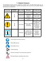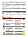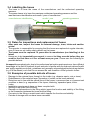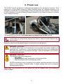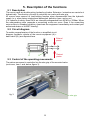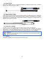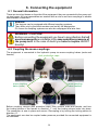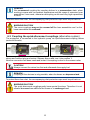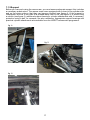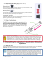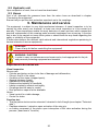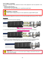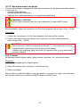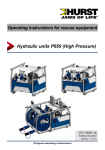
1
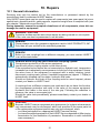
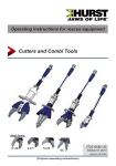
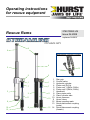
Operating instructions
for rescue equipment
274010085 US
Issue 06.2008
Rescue Rams
replaces 09.2007
6
8
alternative coupling system:
4
5
14
2
1
7
3
3
11
9
10
12
9
13
2
1
1 2
3
4
7 5
6
7
11 8
9
10 10
11
12
13
12 14
Star grip
Control valve
Hydraulic cylinder
Piston rod (R41x)
Piston rod 1 (R42x; R43x)
Piston rod 2 (R42x; R43x)
Handhold
Claw, piston side
Claw, cylinder side
Hose, pressure
Hose, return
Mono-coupling male
Quick-disconnect coupling
(male)
Quick-disconnect coupling
(female)
Content
Page
1. Hazard classes
4
2. Product safety
5
3. Safety regulations for hydraulic hoses
8
3.1 Advices for hoses
9
3.2 Safeguarding the environment in the event of failure of the hoses
9
3.3 Storage of hoses
9
3.4 Labelling the hoses
10
3.5 Dates for inspections and replacement of hoses
10
3.6 Examples of possible defects of hoses
10
4. Proper use
5. Description of the functions
11
12
5.1 Description
12
5.2 Circuit diagram
12
5.3 Control of the operating movements
12
5.4 Type R 41x
13
5.5 Type R 43x / R 42x
13
5.6 Hydraulic supply
13
5.7 Hoses
13
6. Connecting the equipment
14
6.1 General information
14
6.2 Coupling the mono-couplings
14
6.3 Coupling the quick-disconnect couplings (alternative system)
15
7. Operation
16
7.1 Preparatory measures
16
7.2 Danger notes
18
7.3 Operating the star grip (cover: item 1)
19
7.4 Use of extensions
19
8. Dismantling the equipment / deactivation following operation
19
8.1 Rescue ram
19
8.2 Hydraulic unit
20
8.3 Hoses
20
9. Maintenance and service 20
2
10. Repairs
21
10.1 General information
21
10.2 Preventative service
22
10.3 Repairs
23
11. Troubleshooting
26
12. Technical Data
29
33
12.1 Recommended hydraulic fluid
12.2 Hoses
33
12.3 Operating and storage temperature ranges
33
13. Notes
34
3
1. Hazard classes
We distinguish between various categories of safety notes. The table below gives you an
overview of the assignment of symbols (pictograms) and key words to the specific hazard
and possible consequences.
Damage /
injury to
device
human
Pictogram
Key word
Definition
Consequences
DANGER!
Immediate danger
Death or major
injury
WARNING!
Potentially
dangerous
situation
Potential death or
major injury
CAUTION!
Less dangerous
situation
Minor or slight
injury
CAUTION!
Danger of damage
to device /
environment
Damage to the
equipment,
damage to the
environment,
damage to
surrounding
materials
REMARK
Advice for
application and
other important /
useful information
and advice
No injury /
damage to
persons /
environment /
equipment
-
Wear helmet with face protection
Wear safety gloves
Wear safety shoes
Proper recycling
Observe principles of environmental protection
Read and observe operating instructions
4
2. Product safety
HURST products are developed and manufactured in order to guarantee the best performance
and quality when used properly.
Operator safety is the most important aspect of the product design.
Moreover, the operating instructions are intended to help the safe use of HURST products.
The generally applicable, legal and other binding regulations pertaining to the prevention of
accidents and protection of the environment apply and are to be implemented in addition to
the operating instructions.
The equipment may only be operated by persons with appropriate training in the safety
aspects of such equipment – otherwise, there is a danger of injury occurring.
We would like to point out to all users that they should read carefully the operating instructions
and the instructions contained therein before they use the equipment, and that they should
carefully follow such.
We further recommend that a qualified trainer train you in the use of the product.
WARNING / CAUTION!
The operating instructions for the hoses, the accessories and the connected
hydraulic equipment must also be observed!
Even if you have already received instructions on how to use the equipment, you should still
read the following safety notes through again.
WARNING / CAUTION!
Ensure that the accessories and connected equipment used are suitable for
the max. operating pressure!
Please ensure that no body
parts or clothing get stuck
between the visibly moving
parts (e.g. piston claw and
cylinder).
It is prohibited to work under
load if this load is lifted
exclusively by hydraulic
equipment. If this work
is absolutely imperative,
additional mechanical
supports must be used.
Wear protective clothing,
safety helmet with visor,
protective gloves
Inspect the equipment before
and after use for visible
defects or damage
The responsible department
is to be informed immediately
of any changes (including to
the operating behaviour)! If
necessary, the equipment is
to be deactivated immediately
and secured!
Inspect all cables, hoses
and screwed connections for
leaks and externally visible
damage! If necessary, repair
immediately! Squirting oil can
result in injuries and fires.
In the event of malfunctions,
immediately deactivate the
equipment and secure it. The
malfunction is to be repaired
immediately.
Do not carry out any changes
(additions or conversions)
to the equipment without
obtaining the prior approval of
HURST.
5
Observe all safety and danger
notes on the equipment and
in the operating instructions.
All safety and danger notes
on the equipment are to be
kept complete in a legible
condition.
Any mode of operation which
impairs safety and/or stability
of the equipment is forbidden!
Comply with all specified
dates or dates specified in
the operating instructions
pertaining to regular controls /
inspections on the equipment.
Safety devices may never be
deactivated!
The maximum permitted
operating pressure noted on
the equipment must not be
exceeded.
Before the equipment is
switched on/started up, and
during its operation, it must
be ensured that nobody is
endangered by the operation
of the equipment.
Only original HURST
accessories and spare parts
may be used for repairs.
When working close to live
components and cables,
suitable measures must
be taken to avoid current
transfers or high-voltage
transfers to the equipment.
Please note that, when
applying pressure, tearing
or breaking can cause
falling material, or sudden
removal of such can cause
it to suddenly catapult off:
necessary precautions need
to be taken.
Only touch any broken-off
parts wearing protective
gloves, since the torn edges
can be very sharp.
Please ensure that, when
working with this equipment
or during transportation of
such, you don’t get stuck in
the looped hoses and trip.
The build-up of static
charge with the potential
consequence of spark
formation is to be avoided
when handling the equipment.
The equipment is filled
with a hydraulic fluid.
These hydraulic fluids can
be dangerous to health if
swallowed or their vapours
inhaled. Direct contact with
the skin is to be avoided for
the same reason. Please also
note that hydraulic liquids can
also have a negative effect on
biological systems.
6
When working with or storing
the equipment, ensure that
the function and the safety
of the equipment are not
impaired by the effects of
stark external temperatures
or that the equipment is
damaged in any way. Please
note that the equipment can
also heat up over a long
period of use.
Ensure adequate lighting
when you are working.
Before transporting the
equipment, always ensure
that the accessories are
positioned such that they
cannot cause an accident.
Always keep these operating
instructions within reach
where the equipment is used.
Ensure the proper disposal
of all removed parts, left-over
hydraulic fluid, left-over oil
and packaging materials!
The generally applicable, legal and other binding national and international regulations
pertaining to the prevention of accidents and protection of the environment apply and are to
be implemented in addition to the operating instructions.
W A R N I N G
/
C A U T I O N !
The equipment is to be used exclusively for the purpose stated in the operating
instructions (see chapter “Proper Use”). Any other or further use is not considered
proper use. The manufacturer / supplier is not liable for any damages resulting from improper
use. The user bears sole responsibility for such.
Observance of the operating instructions and compliance with the inspection and maintenance
conditions are part of the proper use.
Never work when you are overtired or intoxicated!
7
3. Safety regulations for hydraulic hoses
C A U T I O N !
- Never bring the hoses into contact with brake fluid.
- The hoses are to be cleaned immediately should they come into contact with the following fluids:
• acids, lyes, solvents
• alcohol, fuel and ATF (Automatic Transmission Fluid)
• battery acid
• phosphate ester
It is also imperative that the hoses be inspected for damage following cleaning! If necessary,
the hose assemblies are to be replaced!
1
2
3
4
6
5
Fig. 2
8
3.1 Advices for hoses
-
-
-
-
-
-
The determined operating pressure may not be exceeded.
Tensile load and torsion to the hoses must be avoided (see figure 2, item 1). 1).
Do not kink the hoses (see figure 2, item 2). 2).
Do not drag or lay hoses across sharp edges (see figure 2, item 3). 3).
Do not connect twisted hoses (see figure 2, item 4). 4).
Never drive over the hoses with a motorised vehicle. Hoses laid loosely across roads or
paths are to be protected from damage e.g. by hose protection ramps (see figure 2, item 5).
- In the event of high external temperatures, the hoses are to be installed either at an
adequate distance from the heat-radiating components or are to be protected by suitable
measures (see figure 2, item 6).
- Do not hang any weights on the hoses.
3.2 Safeguarding the environment in the event of failure of the hoses
Hoses must be laid or secured such that, in the event of a failure of the hose, danger is
avoided as far as possible.
Danger can be caused by:
- The hose thrashing about following a tear caused by external influences, for example.
- The pressure media leaking under pressure,
- The lighting of leaking pressure media within the vicinity of an ignition source.
The danger can be avoided by means of protective coverings or screening, for example.
WARNING / CAUTION for hairline cracks!
- Leaking hydraulic fluid under high-pressure can cause serious injuries to the
skin.
- In the event of injuries, immediately consult a doctor!
Hydraulic fluid must immediately be removed from wounds!
- Do not use your fingers to detect leaks!
- Relieve the hydraulic system before you loosen connections!
3.3 Storage of hoses
- Even when stored correctly and used properly, hoses are subject to a natural ageing process. This means that their period of storage and period of use are restricted.
The following is to be observed when storing the hoses:
- Store in a cool, dry and low-dust condition (possibly wrap in plastic film). Avoid direct sunlight and UV rays. Screen from heat sources in the vicinity.
- Do not use any ozone-forming lighting fixtures such as fluorescent light sources, mercury vapour lamps) or electrical equipment close to the equipment.
- Store hoses such that they are stress-free in a flat position. If storing in rings, the smallest bending radius stated by the manufacturer may not be exceeded.
9
3.4 Labelling the hoses
- The hose is to bear the name of the manufacturer and the authorised operating
pressure.
- The press sleeve is to bear the maximum authorised operating pressure and the manufacturers identification and month / year of manufacture.
month / year
operating pressure
manufacturers identification
3.5 Dates for inspections and replacement of hoses
- After each use, inspect the hoses for external damage, tears, kinks and swollen
points!
- The operator is responsible for ensuring that the hoses are replaced at regular intervals,
even if there are no visible safety defects on the hoses.
- The hoses must be replaced 10 years after its manufacture (see labelling) at the
latest!
- Hoses are to be inspected by an expert to ensure that they are safe before they are
used for the first time and then at least once per year. Please see the following for
possible defects.
An expert is somebody who, due to his professional education and experience, has sufficient
knowledge in the field of hydraulic hoses and who is familiar with the relevant national health
and safety regulations at work, guidelines and generally acknowledged technical regulations
(e.g. EN standards) such that he can assess the safe condition of the hydraulic hoses..
3.6 Examples of possible defects of hoses
- Damage to the external layer through to the inside (e.g. abrasive spots, cuts or tears).
- Embrittlement of the external layer (formation of cracks on the hose material).
- Distortions not in line with the natural form of the hoses, in pressure-free or in pressurised
condition or bend, e.g. separation of the layers, blistering, squashed parts, kinks.
- Leaks.
- Installation requirements have not been complied with.
- Shifting of the hose from its fitting.
- Damage or deformations to the fitting which impair the function and stability of the fitting
or the connection between the hose and the fitting.
- Corrosion to the fitting or metal insert which impairs the function and stability.
- Periods of storage and use have been exceeded.
10
4. Proper use
The HURST rescue equipment is designed specifically for the emergency services. Their
objective is to free people trapped in traffic accidents when the clearance distance of a
spreader is insufficient e.g. by spreading or lifting car parts (see figure below). Their objective
in other disasters is to rescue buried or trapped persons (e.g. to remove pieces of concrete
from collapsed houses).
The equipment can also be used under water at a depth of up to 40m (131 ft).
CAUTION!
In this case, you must strictly observe any leaks in order to avoid threats to the
environment.
Basically, objects can be pushed away or their position can be altered.
WARNING / CAUTION!
All objects which have to be moved are to be secured using stable supports or
substructures. Furthermore, it must be ensured that the rescue ram cannot slip.
We recommend that you use support bearings. These are available in the HURST
accessories programme.
WARNING / CAUTION!
The following may not be squeezed:
- live cables
- hardened parts such as steering columns and rollers
- explosive bodies such as airbag cartouches
NEVER operate the rescue equipment at a higher operating pressure than that
stated in the chapter “Technical data”. A higher setting can result in material
damage and/or injuries.
Spare parts and accessories for the rescue tool can be ordered from your authorisied
HURST-dealer!
11
5. Description of the functions
5.1 Description
The rescue rams are double-acting hydraulic cylinders. Extension / retraction are carried out
hydraulically. The direction of travel is controlled via a valve with star grip.
All rescue rams ensure full load-holding function when disconnected from the hydraulic
supply (e. g. when being unintentional decoupled; defective hose, and so on).
(For reasons of safety, rams R414 are internally safeguarded from 63 MPa = 630bar. When
the safeguarding valve responds a screeching noise can occur. Even if the screeching
noise occurs in unloaded condition, deactivate the equipment immediately and contact your
authorized dealer or HURST directly!)
5.2 Circuit diagram
To enable comprehension of the function, a simplified circuit
diagram (hydraulic cylinder of the rescue equipment (A) +
hand valve (B) ) are depicted here.
Extend
piston
A
Retract
piston
B
5.3 Control of the operating movements
The piston movement is controlled via the star grip of the mounted valve.
(see cover, item 1 and, below, figure 3).
fig. 3
star grip
12
5.4 Type R 41x
Type R 41x rescue rams are one-stage cylinders for applying pressure with a constant
pressure force along the entire stroke.
5.5 Type R 43x / R 42x
Type R 43x / R 42x rescue rams are multi-stage cylinders for applying pressure. Depending
on the piston stage, they have varying pressure forces. However, the pressure force remains
constant within one piston stage. An advantage offered by this range is the large stroke at a
relatively low construction height.
5.6 Hydraulic supply
A HURST motor pump or hand pump only may be used to drive the equipment.
If the pump unit is a different make, you must make sure that it complies with HURST
specifications, otherwise potential dangers may occur which are not the responsibility of
HURST. Ensure in particular that the authorised operating pressure is not exceeded.
REMARK:
Before you use pumps from a different manufacturer, you must contact HURST
or an authorised dealer.
5.7 Hoses
The pump unit and the rescue ram are connected by hoses.
13
6. Connecting the equipment
6.1 General information
There are two short hoses on the side of the equipment: they are connected to the pump unit
via two hoses. All hose assemblies are marked with a colour and have couplings to enable
unmistakable connection.
REMARK:
The devices can be equipped with different coupling systems.
They differ only by the article number and not by the designation.
Of course the coupling systems can also be reequipped at a later time.
WARNING / CAUTION!
Before connecting the equipment you have to pay attention that all
used components are suitable to the max operation pressure of
the pump unit! In the case of doubt you have to inquire HURST
directly!
6.2 Coupling the mono-couplings
The equipment is connected to the hydraulic pump via mono-coupling halves (male and
female).
dust protection caps
mono-coupling
halve (male)
mono-coupling
halve (female)
Before coupling, remove dust protection caps, then connect male and female, and turn
the locking sleeve of the female to direction „1“ until the locking sleeve locks into place.
The connection is now in place and secure. Decoupling is by turning the locking sleeve to
direction „0“.
The equipment can also be coupled under pressure provided the connected equipment is
not activated.
14
REMARK:
We recommend coupling the coupling halves in a pressureless state, when
working in areas with low ambient temperature and the usage of extension hose
assemblies / hose reels, otherwise decoupling could need very high expenditure
of force.
To protect them from dust, the accompanying dust protection caps must be put back on.
WARNING/CAUTION!
The mono-couplings may not be screwed off the hose assemblies and / or the
hose assemblies be confused!
6.3 Coupling the quick-disconnect couplings (alternative system)
The equipment is connected to the hydraulic pump via quick-disconnect-coupling halves
(male and female).
X
Y
Before coupling unlock the connect socket by turning the sleeve into position X. Retract
sleeve and connect plug and socket. Release sleeve and turn it into position Y.
Now the connection has been made and locked. Uncoupling is done in the reverse order.
CAUTION!
Always connect the return line first and afterwards the supply line!
REMARK:
Coupling of the devices is only possible, when the hoses are depressurized.
To protect them from dust, the accompanying dust protection caps must be put back on.
WARNING/CAUTION!
The quick-disconnect-couplings partly have special functions. Therefore it is not
allowed to screw them off from the hoses or to exchange them!
15
7. Operation
7.1 Preparatory measures
7.1.1Commissioning
Before commissioning and following repairs, the equipment must be deaerated.
- Connect the equipment to the hydraulic pump (see chapter “Connecting the
equipment”).
- Extend / retract the equipment without any load at least twice (see chapter “Operation
of the star grip”).
REMARK:
We recommend that during the deaeration, the attached aggregate for the
hydraulic supply should stand on a higher level than the body of the rescue
tool.
Recommended procedure for the deaeration of the rescue tool:
1.) open and close fully with the piston rod facing upwards.
2.) open and close fully with the piston rod facing downwards.
3.) open and close fully with the piston rod facing upwards.
4.) open and close fully with the piston rod facing downwards.
7.1.2Inspection of the pump unit
See separate operating instructions for the relevant pump unit (or for the hand pump).
REMARK:
Before each start-up of the hydraulic unit you have to make sure that the actuating
valves are set to depressurized circulation.
REMARK:
Before coupling the quick-disconnect couplings, the actuating valves of the
hydraulic unit are set to depressurized circulation.
If you use mono-couplings, you can also couple when the hoses are pressurized!
16
7.1.2Support
Before you can work using the rescue ram, you must ensure adequate support: this includes
a necessary substructure. The rescue rams come equipped with a claw on the cylinder side
and on the piston side so that they can become hooked (see figure 4). If this support is
inadequate, such as in the case of a pushed-away front of car (see figure 5) or when lifting
a vehicle (see figure 6), additional support bearings, cylinder attachments and, if necessary,
protection using a belt, for example, are also necessary. Appropriate support bearings and
practical cylinder attachments are available from the HURST accessories programme.
fig. 4:
fig. 5:
fig. 6:
17
WARNING / CAUTION!
Never use a rescue ram without claw or adequate accessories! The cylinder could
slip away while moving and this could result ininjuries of the user. Furthermore
the piston rod or the adapter of the claw could be damage thereby.
WARNING / CAUTION!
When positioning the rescue ram (without HURST support bearings), it is
imperative that all four ends of both the piston claw and the cylinder claw are
flush.
When positioning the rescue ram (to a HURST support bearing), it is imperative
that the area between the four ends of the claw are flush with the round bar of
the bearing.
This avoids a one-sided application of force into the cylinder. Lifted objects must
then be secured by means of stable supports or substructures!
7.2 Danger notes
Before activating the rescue ram, always ensure that there is no danger to persons either
involved / uninvolved in the action by the movement of the piston rod or by flying fragments.
Further avoid unnecessary damage to property belonging to others, objects not involved by
the cylinder pistons / flying fragments.
Holding the piston rod during operation of the equipment is
strictly forbidden!
18
7.3 Operating the star grip (cover: item 1)
Extend piston (
):
Turn the star grip in a clockwise direction (in the direction of the
relevant symbol) and keep in this position.
Retract piston (
):
Turn the star grip in an counterclockwise direction (in the direction of
the relevant symbol) and keep in this position.
“Dead-man” function:
Following release, the star grip automatically returns to the central
position, guaranteeing the full load-holding.
7.4 Use of extensions
The R410 rescue ram may only be operated with the
HURST extension (length = 250mm). No other rescue
ram may be operated with an extension: furthermore,
operation is only permitted using the original HURST
extension. The extension is assembled from the righthand side as depicted.
Extension
Rescue Ram
WARNING / CAUTION!
Rescue rams with extensions are to be carefully monitored during their use. If
there are signs of a serious change to its behaviour, work is to be interrupted
immediately and, if necessary, even stopped altogether. After every use /
interruption to use, carefully control the cylinder and the extension for damage!
8. Dismantling the equipment / deactivation following
operation
8.1 Rescue ram
Once work has been completed, the rescue rams are to be retracted so that just a few mm*)
protrude. This relieves the hydraulic and mechanical strain on the equipment.
REMARK:
Due to fluctuations to the ambient temperature, the storage of rescue rams can
cause small lifting motions in the equipment. This effect is a physical reaction to
the expansion of the hydraulic fluid enclosed in the piston and rod side. For this
reason, the storage room for rescue rams is to be designed such that there is up
to 30mm (1.18 in.) space to allow for a potential extension to the length.
*) 1 mm = 0.04 in.
19
8.2 Hydraulic unit
Upon completion of work, the unit must be deactivated.
8.3 Hoses
First of all, decouple the pressure hose then the return hose as described in chapter
“Connecting the equipment”.
Ensure that you put the dust protection caps back on to the couplings.
9. Maintenance and service
The equipment is subject to very high mechanical stresses. A visual inspection is to be
carried out after every use: however, at least one visual inspection is to be carried out
annually. These inspections enable the early detection of wear and tear, which means that
punctual replacement of this wearing parts prevents breakages from occurring. A function
test is also to be carried out every three years or should there be any doubt regarding the
safety or reliability of the equipment.
(Please also observe the relevant valid national and international regulations pertaining to
service intervals of rescue equipment).
CAUTION!
Clean off any dirt before controlling the equipment!
WARNING / CAUTION!
In order to carry out maintenance and repair works, tools appropriate for the job
and personal protecting equipment are essential.
Inspections to be carried out:
Visual inspection
Rescue ram
• Cylinder and piston rod are to be free of damage and deformation,
• Correct, firm fit of the claws,
• Condition of the claws (chipped spots),
• General tightness (leaks),
• Operability of the star grip,
• Existence and stability of handhold,
• Labels completely existent and legibly,
• Couplings must be easy to couple,
• Dust protection caps must be available.
Hoses
• Visual control for visible damage,
• Control for leaks.
Function test
• That the piston stroke can be extracted / retracted to its full length (see chapter “Technical
data”)
• Flawless extension / retraction upon activation of the star grip.
• no further movement of the piston upon interruption of the valve activation during the
process (“dead-man’s” function)
20
10.1 General information
10. Repairs
Servicing may only be carried out by the manufacturer or personnel trained by the
manufacturer and by authorised HURST dealers.
Only HURST spare parts may be used to replace all components (see spare parts list) since
special tools, assembly advice, safety aspects, inspections might have to complied with (see
also chapter “Maintenance and Service”).
During assembly, ensure the complete cleanliness of all components, since dirt can
damage the rescue equipment!
WARNING / CAUTION!
Protective clothes must be worn when repairs are being carried out, since parts
of the units can also be pressurised in an idle state.
REMARK:
Please always return the guarantee registration card to HALE PRODUCTS, INC.
Only then are you entitled to the extended guarantee.
REMARK:
Before you use couplings from a different company, you must contact HURST
or an authorised dealer.
REMARK when using the quick-disconnect-coupling system:
Overpressure protection of the rescue equipment
(model with yellow coupling nipple on the return hose)
If the equipment’s short hoses are not connected to a hydraulic unit, temperature
increases can inadvertently cause pressure to build up in the equipment. Hence,
the return hose of the equipment is equipped with a safety coupling (quickdisconnect coupling male, yellow). Unwanted overpressure (approx. 1.5 Mpa) is
automatically released via this nipple: hydraulic fluid leaks.
Should an hydraulic fluid leak on the coupling male be more frequent, please
contact your dealer or HURST itself.
If couplings from a different company are used which do not have this function,
the overpressure protection can react in the valve of the rescue equipment.
Hydraulic fluid leaks in the area of the star grip. Following the reduction in
pressure, the valve is once again tight.
Should the valve leak permanently, please immediately contact your dealer or
HURST itself.
CAUTION!
Because HURST rescue equipments are appropriate for highest achievements,
only components may be exchanged, which are specified in the spare parts list
of the appropriate equipment.ipment may only be exchanged, when:
- you have participated on a appropriate HURST service training.
- you have the explicit permission of the HURST Service department (After inquiry,
examination for the distribution of permission. Examination in each individual
case necessary!)
21
10.2 Preventative service
10.2.1 Care regulations
The exterior of the equipment is to be cleaned from time to time in order to protect it from
external corrosion. Oil is to be applied to the metallic surfaces.
10.2.2 Function and load test
If there is any doubt regarding the safety or reliability of the equipment, a function and load
test must also be performed.
HURST offers appropriate test equipment to this end.
10.2.3 Changing the hydraulic fluid
- The hydraulic fluid must be changed after the equipment has been used approx. 200
times / after three years at the latest.
- It must always be changed whenever the hydraulic fluid for the accompanying pump
(motor / hand pump) is changed. This is to prevent the fresh hydraulic fluid from becoming
contaminated by the used fluid from the rescue equipment.
Procedure:
1. Completely retract rescue ram.
2. Change the hydraulic fluid of the pump. Please observe the separate operating instructions
for the pump being used!
3. Screw off the return hose on the pump:
- when the hose connection is directly into the pump:
completely unscrew the connection nut of the connection piece of the blue return hose.
- when the hose connection is via mono-coupling to the pump:
remove the cover from the mono-coupling (male).
completely unscrew the connection nut of the blue returnhose on the mono-coupling (male).
- when the hose connection is via quick-connect-coupling to the pump:
completely unscrew the connection nut on the quick-disconnect-coupling of the blue
return hose.
4. Put the return hose into a separate collecting basin for the hydraulic fluid still in the equipment.
5.Slowly extend the rescue ram (the pump must be working during this time). The old
hydraulic fluid from the ring space side runs via the return hose into the separate collecting
basin, and is to be disposed of in the same manner as the old hydraulic fluid of the
pump.
6.Switch the pump off (motor pump) / no longer activate it (e.g. hand pump).
7.Reconnect the return hose to the pump:
- when the hose connection is directly into the pump:
screw the connection nut of the connection piece of the blue return hose back on.
(Please observe the necessary torque of MA = 40 Nm!)
- when the hose connection is via mono-coupling to the pump:
screw the connection nut of the blue return hose back onto the mono-coupling (male).
(Please observe the necessary torque of MA = 40 Nm!)
Pull back the cover on the couplings as far as the limit stop.
- when the hose connection is via quick-connect-coupling to the pump:
screw the connection nut back onto the quick-disconnect-coupling of the blue return hose.
(Please observe the necessary torque of MA = 35 Nm!)
8.Deaerate the rescue ram as described in the chapter “Preparatory measures”.
22
10.3 Repairs
10.3.1 Changing or tightening hoses
Hoses of the pressure and/or return pipe leaks or hoses are defective. Tighten the hoses on
the safety valve.
(Please note! Observe torque of MA = 40 Nm!)
REMARK when using mono-couplings:
If you want to change the hoses, you have to dismantle the mono-couplings.
CAUTION (by usage of mono-coupling-system)!
Take care that the port ‘T’ of the rescue cylinder is always connected to the port
‘T’ of the mono-coupling.
CAUTION (by usage of quick-disconnect-coupling-system)!
The return hose, which is screwed onto the port “T” of the rescue cylinder, must
be equipped with a quick-disconnect-coupling (male) always.
However the supplying hose line must be equipped with a quick-disconnectcoupling (female).
Procedure:
C
B
1. Loosen the 2 “B” screws in the handle sleeve
with quick-disconnect protective sleeves “C”
(hexagon socket)
A
2. Remove handle sleeve A and tighten screwed
connection. If necessary, renew seals.
F
E
D
3. Dismantle hose D and sealing ring E. (There
is no need to carry out this point if the hoses
are just being tightened).
4. Screw the hose with sealing ring back on.
Please ensure that the insulating washer F is
on and correctly assembled.
dismantle
assemble
5. Tighten the hose connection on the safety valve. (Please note! Observe the necessary
torque of MA = 40 Nm!)
6. Then replace handle sleeve, protective sleeves and screws, tighten (Torque: 5Nm) and
secure it with threadlocking fluid (e. g. LOCTITE 243).
23
10.3.2 Mono-couplings
The mono-couplings on the connection hoses of the equipment must be replaced in the
event of:
- external visible damage,
- the locking device not working,
- hydraulic fluid continually leaking in a coupled/uncoupled state.
WARNING / CAUTION!
Never repair couplings: they are to be replaced by original HURST parts!
During assembly, tighten the connection nut of the hose assembly with a torque of MA = 40 Nm.
Procedure:
1. Remove the cover from the couplings.
2. Loosen the connection nuts of the hose assembly and remove the coupling.
3. Position the new coupling and tighten the connection nuts of the hose assemblies with a torque of MA = 40 Nm and push the cover of the couplings back on.
CAUTION!
Take care that the port ‘T’ of the rescue ram is always connected to the port ‘T’
of the mono-coupling.
24
10.3.3 Quick-disconnect-couplings
The quick-disconnect-couplings on the connection hoses on the equipment must be replaced
in the event of:
- external visible damage,
- the locking device not working,
- hydraulic fluid continually leaking in a coupled/uncoupled state.
WARNING / CAUTION!
Never repair couplings: they are to be replaced by original HURST parts!
During assembly, tighten the connection nut of the hose assembly with a torque of MA = 35 Nm.
Procedure:
1. Loosen the connection nut of the hose assembly and remove the coupling.
2. Position the new coupling and tighten the connection nut of the hose assemblies with a torque of MA = 35 Nm.
CAUTION!
The return hose, which is screwed onto the port “T” of the rescue ram, must be
equipped with a quick-disconnect-coupling (male) always.
However the supplying hose line must be equipped with a quick-disconnectcoupling (female).
10.3.4 Labels
All damaged and/or illegible labels (safety notices, type plate, etc.) must be renewed.
Procedure:
1. Remove damaged and/or illegible labels.
2. Clean the surfaces using acetone or industrial alcohol.
3. Attach new labels.
Ensure that you attach the labels in the right position. If you are no longer sure about this,
then please contact your authorised HURST dealer or HURST itself.
25
11. Troubleshooting
Trouble
Control
Cylinder piston
Are the hoses
moves slowly or
connected
jerkily when activated properly?
Does the pump
unit work?
Equipment doesn’t
Have you checked
come up with the full the hydraulic fluid
power.
level in the supply
pump?
Following release,
Is it hard to move
the star grip doesn’t
the star grip?
return to the central
position
with mono-couplingsystem: Hoses
cannot be coupled
Cause
Solution
Air in the hydraulic Deaerate pump
system
system
Insufficient
hydraulic fluid in
the pump
Top up hydraulic fluid,
deaerate
Damage to the
torsion spring for
reset
Soiled valve or
star grip
Defective valve
Other mechanical
damage (e. g. star
grip)
Pressure too high
(e.g. caused by
too-high ambient
temperature)
Coupling defective
Repair by an
authorised dealer, by
personnel specially
trained by HURST, or
by HURST itself
Set hydraulic pump
to pressureless
circulation
Coupling needs to be
replaced immediately
with monocoupling-system:
It is frequently not
possible to couple
hose assemblies
Control the
degree of viscosity
and application
temperature of
the used hydraulic
fluid
Hydraulic fluid
not adapted to
the application
situation
Hydraulic fluid
must be replaced
(see chapter
“Recommended
Hydraulic fluids”)
Coupling defective Coupling needs to be
replaced immediately
with quickdisconnect-couplingsystem: Hoses
cannot be coupled
Is the pump
working?
Pressurized
Relieve pump
Coupling defective Coupling needs to be
replaced immediately
Hydraulic fluid leak
on the hoses or the
fixing-ins
Damages on the
surface of the
hydraulic hoses
Are the hoses
defective?
Leak, possible
damage
Replace hoses
Mechanical
Replace hoses
damages or
contact with
aggressive agents
26
Trouble
Hydraulic fluid leak
on the piston rod
Control
Cause
Leak on the handhold Increase load?
Is the set pressure
on the pump
adapted to comply
with the maximum
permissible
pressure for
the rescue
equipment?
Hoses in handhold
loose?
Check the
connections of the
mono-coupling
(female)
Is the return
hose connected
correctly?
Solution
Defective rod seal Repair by an
authorised dealer, by
Damage to the
personnel specially
piston
trained by HURST, or
by HURST itself
Secure the loads and
Load increase
move them by using
(e.g. something
has fallen onto the other tools
part to be lifted,
Position ram on a
thereby suddenly different place, where
increasing the
the load to be moved
load)
is lower
Use supporting
equipment to move
the load.
Pressure release Following the
in the Rescue tool. reduction in pressure,
no further leak is
present.
Should, however,
there be a further
leak on the handhold,
immediately
deactivate the rescue
equipment, and
contact an authorised
dealer or HURST
itself.
Hoses in handhold Tighten hoses.
not tightened
Supply and return Reconnect the
connection of the hoses of the monocooupling (female) in
mono-coupling
(female) inverted the right way
Return hose is not Re-connect the return
coupled correctly hose and secure it.
or not connected.
Especially by usage
of quick-disconnectcouplings: Leak on
the handhold
Especially by usage check the
hose connection
of mono-couplings:
connections of the to the couplings
Leak on the handhold hoses
interchanged
Returnline
disabled
27
reconnect the hoses
to the coupling in the
right way
disconnect the
returnline from the
coupling, clean it and
reconnect it.
Trouble
with mono-couplingsystem: Leak in the
couplings
with quickdisconnect-couplingsystem: Leak in the
couplings
Control
Cause
Solution
Is the coupling
damaged?
coupling damaged Coupling must be
replaced immediately
Is the coupling
damaged?
coupling damaged Coupling must be
replaced immediately
Is the leak only
Safety valve
on the coupling
reacted
male (in uncoupled
status)?
After pressure
release there is no
more leakage.
If it isn’t possible to rectify the malfunctions, inform an authorised HURST dealer or the
HURST customer service department immediately!
The address for the HURST customer service department is:
HURST
JAWS OF LIFE
HALE PRODUCTS, INC.
A Unit of IDEX Corporation
711 N. Post Road
Shelby, NC 28150 USA
Phone: (704) 487-6961
Fax:
(704) 487-7271
e-mail: [email protected]
28
12. Technical Data
Since all values are subject to tolerances, minor differences may occur between the data on
your equipment and the data in the following schedules!
Type
Ref. No.
Pressure force
(piston 1)
Pressure force
(piston 2)
Pressure force
(piston 3)
R 430
274070000
266
266
59,802
59,802
[kN]
133
133
[lbf.]
29,901
29,901
[kN]
-
39
[lbf.]
max. stroke
(piston 2)
[mm]
max. stroke
(piston 3)
[mm]
Piston stroke
overall
[mm]
Dimensions
wxh
R 424
274060000
[kN]
max. stroke
(piston 1)
Length (extended)
R 422
274050000
[lbf.]
[mm]
Length (retracted)
R 420
274040000
[in.]
[in.]
365
445
295
11.61
14.37
17.52
11.61
280
340
430
280
11.02
13.39
16.93
11.02
-
[in.]
[in.]
[mm]
[in.]
8,768
295
245
-
9.65
575
705
875
820
22.64
27.76
34.45
32.28
480
550
625
475
18.90
21,65
24.61
18.70
[mm]
1055
1255
1500
1295
[in.]
41.54
49.41
59.06
50.98
[mm]
[in.]
112 x 211
112 x 210
4.41 x 8.31
4.41 x 8.27
Weight including
hydraulic fluid
filling
[kg]
16,9
18,9
21,1
17,8
[lbs.]
37.3
41.7
46.5
39.2
max. operating
pressure
[MPa]*
min. needed
volume of
hydraulic fluid
[l]**
1,5
1,8
2,2
1,6
[gal.-US]
0.40
0.48
0.58
0.42
coupling system
*
**
70
[psi.]
10,153
mono-coupling
1 MPa = 10 bar
Necessary volume of hydraulic fluid in the hydraulic unit to operate the unit (differential volume on piston / rod side)
29
Type
Ref. No.
R 410
R 412
R 414
274010000
274020000
274030000
[kN]
Pressure force (in
all operating ranges) [lbf.]
Piston stroke
Length (retracted)
Length (extended)
[mm]
[in.]
[mm]
[in.]
[mm]
[in.]
122
27,428
300
500
700
11.81
19.69
27.56
450
680
900
17.72
26.77
35.43
750
1180
1600
46.46
62.99
29.53
Dimensions
wxh
[mm]
Weight including
hydraulic fluid
filling
86 x 174
[kg]
13,1
17,8
24,3
[lbs.]
28.9
39.2
53.6
max. operating
pressure
[Mpa] *
[in.]
3.39 x 6.85
70
[psi.]
min. needed
[l] **
volume of hydraulic
[gal.-US]
fluid
10,153
0,5
0,8
1,2
0.13
0.21
0.32
coupling system
*
**
135
30,351
mono-coupling
1 MPa = 10 bar
Necessary volume of hydraulic fluid in the hydraulic unit to operate the unit (differential volume on piston / rod side)
30
Type
Ref. No.
R 420
R 422
R 424
R 430
214070000
214040000
214060000
214050000
Pressure force
(piston 1)
[kN]
266
266
[lbf.]
59,802
59,802
Pressure force
(piston 2)
[kN]
133
133
[lbf.]
29,901
29,901
Pressure force
(piston 3)
[kN]
-
39
[lbf.]
-
8,768
max. stroke
(piston 1)
[mm]
max. stroke
(piston 2)
[mm]
max. stroke
(piston 3)
[mm]
Piston stroke
overall
[mm]
Length (retracted)
Length (extended)
Dimensions
wxh
[in.]
[in.]
295
365
445
295
11.61
14.37
17.52
11.61
280
340
430
280
11.02
13.39
16.93
11.02
-
[in.]
245
-
9.65
575
705
875
820
22.64
27.76
34.45
32.28
480
550
625
475
[in.]
18.90
21,65
24.61
18.70
[mm]
1055
1255
1500
1295
[in.]
41.54
49.41
59.06
50.98
[in.]
[mm]
[mm]
[in.]
112 x 211
112 x 210
4.41 x 8.31
4.41 x 8.27
Weight including
hydraulic fluid
filling
[kg]
16,9
18,9
21,1
17,8
[lbs.]
37.3
41.7
46.5
39.2
max. operating
pressure
[MPa]*
min. needed
volume of
hydraulic fluid
[l]**
1,5
1,8
2,2
1,6
[gal.-US]
0.40
0.48
0.58
0.42
70
[psi.]
10,153
coupling system
*
**
quick-disconnect-coupling
1 MPa = 10 bar
Necessary volume of hydraulic fluid in the hydraulic unit to operate the unit (differential volume on piston / rod side)
31
Type
Ref. No.
R 410
R 412
R 414
214010000
214020000
214030000
[kN]
Pressure force (in
all operating ranges) [lbf.]
Piston stroke
Length (retracted)
Length (extended)
[mm]
[in.]
[mm]
[in.]
[mm]
[in.]
122
27,428
300
500
700
11.81
19.69
27.56
450
680
900
17.72
26.77
35.43
750
1180
1600
46.46
62.99
29.53
Dimensions
wxh
[mm]
Weight including
hydraulic fluid
filling
86 x 174
[kg]
13,1
17,8
24,3
[lbs.]
28.9
39.2
53.6
max. operating
pressure
[Mpa] *
[in.]
3.39 x 6.85
70
[psi.]
min. needed
[l] **
volume of hydraulic
[gal.-US]
fluid
10,153
0,5
0,8
1,2
0.13
0.21
0.32
coupling system
*
**
135
30,351
quick-disconnect-coupling
1 MPa = 10 bar
Necessary volume of hydraulic fluid in the hydraulic unit to operate the unit (differential volume on piston / rod side)
32
12.1 Recommended hydraulic fluid
Mineral oil ISO 6743-4 for HURST hydraulic equipment and others
Oil temperature range
-20 .... +55°C
Oil code
HM 10
Viscosity rating
VG 10
Remarks
A
Oil temperature range
-4.0 .... +131°F
Oil code
HM 10
Viscosity rating
VG 10
Remarks
A
recommended viscosity range: 10...200 mm²/s
Supplied with HM 10 ISO 6743-4.
(10…200 cSt.)
CAUTION!
Before using hydraulic fluids, which do not correspond to the above-mentioned
specifications and/or are not purchased from HURST, you have to contact
HURST itself!
12.2 Hoses
Bending radius
Rmin = 38 mm (Rmin = 1.5 in.)
Pressure resistance
Safety factor: Burst pressure / max. Operating pressure,
min. 4 : 1
Temperature resistance - 40°C ... + 100°C (- 40°F … + 212°F)
Operating fluid
Mineral oil according to ISO 6743-4
12.3 Operating and storage temperature ranges
Operating temperature
[°C]
-20
…
+55
Ambient temperature
(device in operation)
[°C]
-25
…
+45
Storage temperature
(device not in operation)
[°C]
-30
…
+60
[°F]
-4
…
+131
Operating temperature
Ambient temperature
(device in operation)
[°F]
-13
…
+113
Storage temperature
(device not in operation)
[°F]
-22
…
+140
33
13. Notes
34
35
Please dispose all packaging materials and
dismantled parts properly
HURST
JAWS OF LIFE
HALE PRODUCTS, INC.
A Unit of IDEX Corporation
subject to revision
711 N. Post Road
Shelby, NC 28150 USA
Phone: (704) 487-6961
Fax:
(704) 487-7271
e-mail: [email protected]
Rescue_Ram_BA_DRUCK_US_274010085_0608.indd
© Copyright 2008 Hale Products, Inc.