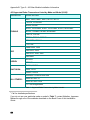
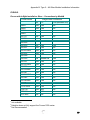
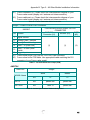
1
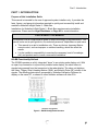
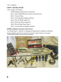
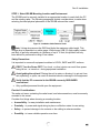
®
Nobeltec Installation Guide for the
InSight™ Radar 2 – Black Box
Higher Resolution…Greater Confidence
Safety & First Aid warnings
SAFETY & FIRST AID WARNINGS
ATTENTION – READ CAREFULLY
PRIOR TO INSTALLATION
Your Ship’s Radar System has a power supply that can easily injure or kill.
NEVER ASSUME POWER TO THE RADAR SYSTEM IS OFF – Always consult your
ship’s wiring schematics.
•
•
•
Secure power to your Ship’s Radar System by placing the power breaker in
the OFF or OPEN position.
Remove all fuses (even spares) from circuits where a switch might
unintentionally be closed.
Verify power is secured by testing the circuit with a multimeter.
All personnel engaged in the installation, operation, and maintenance of electronic
equipment, or those who are engaged in training personnel on electronic equipment,
have a duty to know the following safety precautions:
1. High Voltage:
DO NOT RELY on safety devices
USE GROUNDING STICKS AND CABLES when working with high
voltage circuits
USE RUBBER GLOVES that have been tested within the last six months
when applicable
KEEP YOUR FEET CLEAR of objects on the floor
STAND ON A RUBBER MAT or non-conductive flooring
Whenever possible, HAVE ANOTHER PERSON PRESENT, who is
qualified in FIRST AID for ELECTRICAL SHOCK
2. Low Voltage:
Use a ground mat to prevent static electricity discharges
Do not touch any electronic card components when the power is ON
Always disconnect the power when a system is not in use
Power down before you change any hardware devices - a power surge
could damage the electronic components or the whole system
Piezo ignited soldering irons could damage integrated circuit boards
(ICBs)! Only use a piezo-ignited soldering iron only at a safe distance
from ICB electronics!
3. Rescuing Shock Victims:
PROTECT YOURSELF with DRY insulating material
BREAK THE CIRCUIT by opening the power switch or, using insulating
material, pulling the victim free of the live conductor
DO NOT TOUCH THE VICTIM WITH YOUR BARE HANDS UNTIL THE
CIRCUIT IS BROKEN
2
Table of Contents
SAFETY & FIRST AID WARNINGS........................................................................................................... 2
INSIGHT RADAR 2 – BLACK BOX PRODUCT DESCRIPTION .............................................................. 5
PRODUCT BOX PHYSICAL CONTENTS ......................................................................................................... 5
PRODUCT SPECIFICATIONS AND SYSTEM REQUIREMENTS ........................................................................... 6
PART 1: INTRODUCTION ......................................................................................................................... 7
PURPOSE OF THIS INSTALLATION GUIDE ..................................................................................................... 7
PART 2: INSTALLATION........................................................................................................................... 8
IR2-BB INSTALLATION PREPARATION AND OVERVIEW................................................................................. 8
STEP 1: SELECT IR2-BB MOUNTING LOCATION AND ENVIRONMENT ........................................................ 11
STEP 2: CONNECT WIRING .................................................................................................................... 13
STEP 3: INSTALL NOBELTEC NAVIGATION SOFTWARE .............................................................................. 17
STEP 4: RUN THE IR2-BB INSTALLER CD............................................................................................... 18
STEP 5: SELECT THE RADAR ANTENNA FILE ........................................................................................... 20
STEP 6: RUN THE RADAR SETUP WIZARD ............................................................................................... 21
STEP 7: LAUNCH NOBELTEC NAVIGATION SOFTWARE ............................................................................. 22
PART 3: USING RADARSAMPLE TO SET UP THE IR2-BB ................................................................. 24
RADARSAMPLE OVERVIEW ...................................................................................................................... 24
STEPS TO CONFIGURE A NON-NOBELTEC RADAR USING THE RADARSAMPLE PROGRAM: ........................... 25
SETTING ANTENNA-SPECIFIC PARAMETERS.............................................................................................. 25
APPENDIX A: GENERAL MAINTENANCE AND TROUBLESHOOTING.............................................. 27
HARDWARE DIAGNOSTICS ....................................................................................................................... 27
TROUBLESHOOTING RADAR DATA USING RADARSAMPLE .......................................................................... 30
APPENDIX B: TYPE 2 – ALL OTHER MODELS INSTALLATION INFORMATION .............................. 37
RADAR COMPATIBILITY ............................................................................................................................ 37
ACRONYMS ............................................................................................................................................. 37
RADAR WIRING TABLES ........................................................................................................................... 37
NOBELTEC LEGAL DISCLAIMER AND LIMITED WARRANTY ........................................................... 43
3
4
InSight Radar 2 – Black Box Product Description
INSIGHT RADAR 2 – BLACK BOX PRODUCT DESCRIPTION
Jeppesen Marine’s Nobeltec® InSight™
Radar 2 - Black Box (IR2-BB) radar
solution provides high-resolution radar
data and functionality in conjunction with
Nobeltec Navigation Software.
The IR2-BB receives radar data from
the Radar Head Unit, conditions and
digitizes raw radar signals, and converts
radar echo data into digital radials. Data
is transmitted over a high-quality USB
cable to a USB 2.0 port on any new or
existing navigation PC or laptop similarly
equipped.
The IR2-BB matches connection
specifications for many of the industry’s
leading X- or C-band radar models.
Contact your Nobeltec product
distributor to verify if your system
interfaces with the IR2-BB.
The IR2-BB is designed for intuitive
usage and command execution. With a
familiar appearance similar to a
common radar screen, users will quickly
become adept at operating the IR2-BB
system.
This Installation Guide covers the key
installation information for the IR2-BB. It
is written for an audience assumed to
have a mid-level, pre-existing
knowledge of PC operation and the
principles of marine navigation, as well
as previous marine installation
experience.
This document should in no way be
used to replace actual navigation
training and experience.
Product Box Physical Contents
Your IR2-BB product box should contain the following items:
•
•
•
•
•
•
One (1) IR2-BB conversion device (black box that processes radar signals)
Three cables:
o One (1) 12V Power cable
o One (1) USB 2.0 data cable
o One (1) radar interface cable (with Furuno® slave output connector)
One (1) Nobeltec Visual Navigation Suite Software CD
o One (1) Radar Unlock Code Voucher
One (1) IR2-BB Installation CD
Serial Number Sticker
Three (3) manuals including:
o This Installation Guide
o One (1) Nobeltec Visual Navigation Suite Software User’s Guide
o One (1) InSight Radar Operator's Manual
5
InSight Radar 2 – Black Box Product Description
Typical Installation
Figure 1 - Typical IR2-BB Installation
Product Specifications and System Requirements
Specification
Basic Box
Weight
405 g (14.3 oz)
Dimensions
18.5 cm x 10.9 cm x 3.5 cm (7.3" x 4.3 in x 1.4")
Power
10-36 VDC
Radar source data
Digitization and processing
Samples/radial
512
Radials/image
1024 (360°)
Display
Real-time radar data
Interface
USB 2.0 that connects to a Type-A or Type-B
male connector (using high-quality USB cable)
Networking
Ethernet with TCP/IP (through client PC)
Multi-client support
Yes (through client PC)
Control Configuration
Slave
Computer Operating System
Windows® XP or Windows® 2000
Table 1 - IR2-BB Specifications
6
Part 1: Introduction
PART 1: INTRODUCTION
Purpose of this Installation Guide
This manual is intended for the use of approved system installers only. It provides the
facts, figures, and general information required to quickly and successfully install and
maintain a Nobeltec InSight Radar 2 - Black Box.
Installation of a Nobeltec InSight Radar 2 - Black Box requires marine installation
experience. Please see the Legal Disclaimer on Page 43 for more information.
A NOTE ABOUT THIS MANUAL
This manual is not a comprehensive guide to radar technology or ship electronics. This
manual is also not a quick guide for non-technical personnel, shipbuilders or end users.
•
•
This manual is an aid to installation only. There are factors Jeppesen Marine
cannot control, such as improper or careless handling, which can affect the
results.
It is the installer’s responsibility to exercise the necessary level of knowledge,
skill, and prudent care to insure a successful installation.
IR2-BB Functionality Defined
The IR2-BB operates as a fully integrated “slave” to an existing radar display unit. With
an open loop connection to a previously installed radar display, the slave listens to
signals being passed from the transceiver to the radar display. The slave unit digitizes
the Video, Trigger, Ship’s Heading Marker (SHM), and Bearing Pulse (BP) subset of the
signals. The resulting radar data is processed by Nobeltec Navigation Software for
display on the same PC, or shared to other Nobeltec software on other PCs.
Figure 2 – IR2-BB Configuration Structure
7
Part 2: Installation
PART 2: INSTALLATION
Part 2 contains the following:
IR2-BB Installation Preparation and Overview
Step 1: Select IR2-BB Mounting Location and Environment
Step 2: Connect Wiring
Step 3: Install Nobeltec Navigation Software
Step 4: Run the IR2-BB Installer CD
Step 5: Select the Radar Antenna File
Step 6: Run the Radar Setup Wizard
Step 7: Launch Nobeltec Navigation Software
IR2-BB Installation Preparation and Overview
The InSight Radar 2 - Black Box is designed and developed for reliability and flexibility.
Proper installation will insure long life of the product in harsh marine environments.
The following installation tools are recommended:
Sandpaper
Voltmeter
Mini Propane
Heater
4“ Ties
3/8“ Drill
6“ Ties
Hand
Riveter
Files
Clamps
Wire
Cutters
Solder
Shrink
Tubing
Metal Saw
Needlenose
Pliers
Short-nosed
pliers
Robertson
Phillips Screw Drivers
Socket
Screw Drivers
Cutting
Slot Head
Drivers
Knife
Screw Drivers
Figure 3 - Installation Tools
8
Keyhole
Saw
Electrician’
Tape
Part 2: Installation
Tool
Comment
Tool
Comment
Chisels
Clamps
Crescent wrench
Wood
Various size
8”
Pliers
Pliers
Propane Torch
Drill bits
Full set
Sandpaper
Electric drill
3/8” or ½”
Screwdrivers:
Phillips
Robertson
Slot
Small & medium
sizes
Solder
Soldering iron
Flux core
Fine tip
Voltmeter
Basic
Wire ties
Various sizes
Electrician’s tape
Files
Hand Riveter
Heat shrink tubing
Jig saw
Keyhole saw
Wood
¼” O.D.
Scrolling
blades
Wood &
metal blades
Needle nose
Short nose
Small
Coarse and
medium
Table 2 - Installation Tools
Installation Types
The IR2-BB is compatible with most Radar models using one of two interface methods:
•
Type 1 – Furuno w/ Slave Output Installation: Connection of the IR2-BB to
Furuno Radar with Slave Output.
•
Type 2 – All Other Models Installation: All other Radar models, brands, and types,
(including Furuno without Slave Output)
If you should encounter any undocumented problems while connecting Nobeltec
equipment to your Radar model, please contact Nobeltec using one of the methods
described on the Back Cover of this Installation Guide.
Preparing the Workplace
Confirm the install location is ready (See Step 1 on Page 11):
•
•
•
•
•
Bulkheads and cabinets are accessible, dry, well-ventilated, and protected from the
elements;
The IR2-BB must be mounted within 1.8 meters (6 feet) of the radar plotter.
Work area is available, nearby, and protected from elements
Work area is free of other construction or installation work
Radar is functional and ready to connect
9
Part 2: Installation
Planning the Work
•
Assemble the tools and material required for the installation (see Table 2 Installation Tools on Page 9).
•
Type 1 – Furuno w/ Slave Output Installation: Insure that Furuno Slave Output
connector is accessible.
•
Type 2 – All Other Models Installation: Insure radar signal cables are installed and
ready to connect, or identify where the existing radar signal will be accessed (refer to
the radar and transceiver installation manuals for precise specifications).
•
Confirm the power installed is adequate and routed through a circuit breaker, and
the wiring is accessible.
IMPORTANT: In advance of installation, be sure to redeem the radar unlock
voucher that shipped with your IR2-BB at www.nobeltec.com. In order to obtain the
radar unlock code, you will need to provide your Nobeltec software Serial Number along
with the voucher number (see Page 17).
Installing the System
•
Follow the step-by-step instructions in Step 1 on Page 11 to complete the physical
mounting and electrical/wiring of the InSight Radar 2 – Black Box system.
•
Refer to the settings in Step 5 on Page 20 for the correct settings for your particular
radar transceiver.
Completing the Installation
•
Verify that all connections are secure.
•
After completing Steps 1-7, turn on the power. The radar should still be functional
with the original display.
•
Install and configure your Nobeltec Navigation Software on the client computer(s).
Tip: Refer to your Nobeltec Navigation Software User’s Manual, Set-up section, for
detailed instructions regarding how to implement that software.
10
Part 2: Installation
STEP 1: Select IR2-BB Mounting Location and Environment
The IR2-BB must be securely installed in an appropriate location to reach both the PC
and the existing radar. The following paragraphs include considerations to make when
selecting the ideal physical placement of the IR2-BB onboard the vessel.
Figure 4 – Installation Cable Distance Limits
Note: Voltage drop across the GND lead limits the maximum cable length. This
voltage drop is dependent on cable gauge. While longer USB 2.0 (high-quality) cables
are likely to perform adequately at a distance of up to 15 feet, this product has only
been tested for performance using 6-foot cables.
Safety Precautions:
It is important to secure all equipment modules to LEVEL, SAFE and DRY surfaces.
FIRST: Turn the Power OFF! Fire, shock, or other injuries can result from power
being left on - or turned on - during equipment installation.
Avoid getting the unit wet! Placing the unit in water or allowing it to get wet from
rain, splashing, or spills, can result in electrical shock or damage to the equipment.
Verify that the PC connected to the IR2-BB uses only GROUNDED
connections!
•
Only qualified personnel should open the equipment.
Practical Considerations:
The radar unit case, containing the radar board, and interconnections, must be securely
mounted to the vessel.
Consider four things when choosing a mounting location:
•
Accessibility - for easy installation and maintenance
•
Proximity - to power and signal wiring in place or effective routes for new wiring
•
Safety - to prevent damage to its contents or the cabling in adverse weather
•
Durability - to insure reliable operation over time.
11
Part 2: Installation
Mounting Locations
•
Shipboard installations require that every mounting location effectively protect radar
components from:
o
o
o
o
Water and excessive humidity (rust and corrosion);
Hot environments (overheating);
Sunlight (visibility and overheating); and
Physical damage.
•
Unit must be supported securely in a position where it is easy to access the unit
components (power switch and wiring) as required.
•
Closed spaces must allow and provide a flow of air sufficient to cool the IR2-BB to
normal operating temperatures without causing condensation on or inside the unit.
•
Keep clearance dimensions of at least 100 mm (4 inches) around the fan intake and
exhaust louvers to prevent possible overheating.
•
Add an appropriate allowance for strain relief to the measured length of cables
before installation.
Environment
Humidity and temperature are the two key environmental factors.
Arctic winters and tropical summers are significantly different from each other, and
impose different operating requirements to minimize the impact of each.
Proper installation takes into consideration the widest range of conditions to which the
vessel may be exposed in the course of its operating life.
Table 3 contains the basic specifications for a dry, non-condensing environment.
Nobeltec
Operating Conditions Range
Model Name
Temperature
Humidity
IR2-BB
0° - 45° C
85%
Table 3 - IR2-BB Operating Conditions Ranges
12
Part 2: Installation
STEP 2: Connect Wiring
Figure 5 - IR2-BB Back Panel
STEP 2A: Connect the Radar Interface Cable
Connection to the existing radar antenna varies by model and vendor type.
Figure 6 - Radar Interface Cable
For a Type 1 – Furuno w/ Slave Output Installation:
1. Attach the DB15-pin Radar Interface Cable connector to the IR2-BB DB15-pin
port (Note that the IR2-BB port is labeled Radar Interface).
2. Attach Flat 11-pin Radar Interface Cable connector to the Furuno slave output
port. (Note that the Radar Interface Cable ships with a Flat-11pin connector for
connecting to a Furuno slave output connector).
For a Type 2 – All Other Models Installation:
1. Attach the DB15-pin Radar Interface Cable connector to the IR2-BB DB15-pin
port (Note the IR2-BB port is labeled Radar Interface).
2. Remove (or cut) Furuno slave output connector from the other end of the cable.
3. There are 4 ways to access radar signal:
a.
b.
c.
d.
An existing transceiver-to-display unit cable
A Slave output option connector (for non-Furuno radars)
A radar display Buffer Board connector, or
A Slave Connector Block (SCB) within the radar transceiver
In all cases, specific data feeds from the radar must be connected to the IR2-BB
data cable. This requires soldering and/or splicing the connections together.
Refer to Addendum B for more information.
Tip: For both types of installation, ground wires also must be connected.
13
Part 2: Installation
Soldering/Splicing the Data Cable
Figure 7 – Data Cable Connector Pin Diagram
14
Part 2: Installation
STEP 2B: Connect the USB 2.0 data cable
The provided USB 2.0 data cable can now be connected to the IR2-BB and any
available USB 2.0 port on the onboard PC.
Figure 8 - USB 2.0 data cable
Tip: It is crucial that the USB 2.0 data cable is securely attached to the IR2-BB
device, especially if the IR2-BB is mounted on a wall or upside down. It is
recommended that the USB 2.0 data cable be fastened in such as way that it will not
come loose from the IR2-BB at any time.
Figure 9 - Power Cable
15
Part 2: Installation
STEP 2C: Connect the Power Cable
Route 12 VDC power to the unit via a breaker on the ship’s main or distribution panel,
connecting to the main radar switch/breaker whenever possible.
Connect +ve to +ve, -ve to –ve.
WARNING: Insure the power connection runs through a circuit breaker
equipped with an on/off switch!
External Power Supply Pin Connections
The InSight radar system is configured for 12 VDC. It draws on average 1.5 ampere @
12 VDC. Power is wired through a two-pin connector. The external power connector
wiring is pictured in Figure 10.
Figure 10 - Power Connection Cable
Power Requirements (w/o transceiver)
Radar
Model
IR2-BB
12 VDC
Operating
Range
VDC
Max. Power Consumption
10 - 36
5.5W
Table 4 - System Power Requirements
16
Part 2: Installation
STEP 3: Install Nobeltec Navigation Software
Both Nobeltec Admiral™ and Visual Navigation Suite (VNS)™ are capable of
displaying radar feeds from the IR2-BB and are designed to support this product.
If you have not yet installed one of these navigation software packages on your PC,
please do so at this time.
Assistance with installation of the Nobeltec Navigation Software is included in the
Nobeltec Navigation Software User’s Guide.
STEP 3A: Unlock Radar Functionality within the Navigation Software
Once the software is installed, the radar functionality must be unlocked with an Unlock
Code. Use the voucher included with the product box (see Page 5) to redeem the
voucher and obtain the Radar Unlock Code (see Figure 11).
Note: For users of Nobeltec Navigation Software versions 7.x, refer to your User’s
Guide for unlock instructions.
Figure 11 - Example of Voucher Redemption Webpage
The Radar Unlock Code can then be entered into the Nobeltec Navigation Software
application.
1.
From the Chart Table, select Permits and Unlock Codes.
2.
Click the Install button, and then enter the unlock code in the provided field.
Figure 12 - Example of Radar Unlock Code Window
3. Once the code is accepted, the program can be closed.
17
Part 2: Installation
STEP 4: Run the IR2-BB Installer CD
The IR2-BB Installation CD, which shipped with the IR2-BB, can now be inserted into
your computer. This CD installs the drivers required for the Nobeltec Navigation
Software to communicate with the IR2-BB.
Follow the installation wizard, restarting the computer when prompted, as shown in
Figures 13-16.
Figure 13 – Nobeltec IR2-BB Installer Welcome Screen – Click Next
Figure 14 – Installing Progress Bar(s)
18
Part 2: Installation
Figure 15 – Installation Complete – Click Finish
Figure 16 – Restart Your Computer – Click OK
19
Part 2: Installation
STEP 5: Select the Radar Antenna File
Once the installation of the IR2-BB is complete and your computer has rebooted, the
Settings program window will appear. Use this window to select a Radar Antenna file.
IR2-BB uses the information contained in the selected Radar Antenna File to interpret
the radar signals. If the Settings program does not appear after install, or if you need to
select a different antenna file, run this program manually. The Settings Program for this
file is located in C:\\Program Files\Nobeltec\horizonserver.exe.
This list contains all known radar types at the time of the IR2-BB’s release (10/05).
Select your radar from the list, click SAVE, and then click START.
Figure 17 - Example of Settings Program List of Supported Radars
If your radar type does not appear in this list, check with Nobeltec Technical Support - a
new radar antenna file may be available for you. Otherwise, select the closest match,
click SAVE, click START, and then go to Part 3 on Page 24 to fine-tune your radar
antenna file.
20
Part 2: Installation
STEP 6: Run the Radar Setup Wizard
The radar can now be powered on - use the existing radar display to operate the radar
so that it is broadcasting and displaying returns.
Next, run the Radar Setup Wizard:
From the Start menu, select Start→Programs→Nobeltec→Radar Setup Wizard.
The Radar Setup Wizard will detect the IR2-BB and save the settings needed for the
Nobeltec Navigation Software to see the device when it is started.
Follow the steps in the Setup Wizard (see Figures 18-23) to configure, calibrate and
adjust your radar.
Figure 18 – Radar Setup Wizard Welcome Screen – Click Next
Figure 19 – Radar Setup Wizard - Port Configuration – Click Next
21
Part 2: Installation
Figure 20 – Radar Setup Wizard - Search for
Radar – Click Next
Figure 22 – Radar Setup Window - Adjust
Radar Image – Click Adjust to modify settings
Figure 21 – Radar Setup Window - Radar
Status – Click Next
Figure 23 – Radar Setup Window Completed –
Click Finish
STEP 7: Launch Nobeltec Navigation Software
Now that the hardware has been configured, you are ready to view the radar data inside
of Nobeltec Navigation Software.
1. Double-click on the Nobeltec Software Icon, or
2. Click START→Programs→Nobeltec→Nobeltec Navigation
3. The Radar Window will open in Standby Mode (see Figure 24).
22
Part 2: Installation
Figure 24 – Insight Radar Display window
4. Click Transmit
in the left-hand toolbar
5. A radar image will then display in the display window – see your InSight Radar
Operator’s Manual for information on how to use this display
Figure 25 – Insight Radar Display – Transmitted Radar Image
23
Part 3: Using RadarSample to set up the IR2-BB
PART 3: USING RADARSAMPLE TO SET UP THE IR2-BB
Note: You may not need to perform Part 3 – this section is only used to configure
radar without a correct Radar Antenna File to select from in Part 2 – Step 5, or to
perform fine-tuning of your radar signal.
The IR2-BB ships with an installation CD containing the RadarSample program. This
utility is used to verify correct installation and setup of your IR2-BB product. You can
also use this program to configure a radar antenna when a Radar Antenna File has not
yet been created.
As noted in Part 2 – Step 5 (see Page 20), the software running on the onboard PC
needs to know which radar antenna it is connected to. Step 5 describes how to select a
Radar Antenna File from a list of known antenna types (see Figure 17 on Page 20).
If your particular radar does not appear in that list, the RadarSample program is used to
configure a new Radar Antenna File.
RadarSample Overview
The main RadarSample window shows
the radar image (see Figure 26).
You can adjust this image for range,
orientation, and centering, as well as the
standard radar adjustments (gain, rain
and sea clutter suppression, etc.), using
the settings in the RadarSample Main
USB Settings window (see Figure 27).
Figure 27 - RadarSample Main Window
Figure 26 - RadarSample Main USB Settings
Window
24
Part 3: Using RadarSample to set up the IR2-BB
Steps to Configure a Non-Nobeltec Radar Using the RadarSample Program:
1. Power on the IR2-BB and the radar. Verify that the radar is working properly
2. Launch the RadarSample.exe program from:
Start→Programs→Nobeltec→Visual Series→Radar→RadarSample.exe
3. Select USB from the Action drop-down menu;
4. Select the radar antenna that the IR2-BB is interfaced to – this should match the
antenna selected when setting up the Server software in Step 5 on Page 20;
Note: The RadarSample window will now be titled RadarSample - USB.
5. Remove the checkmark next to Standby in the Action menu (taking the IR2-BB
out of standby mode).
6. The USB Settings window will display
a. At this point, you should see radar imagery in the RadarSample image
window, similar to that shown in Figure 27. You may off-center this image
using the left mouse button when the mouse is anywhere in the Radar Image
Display window.
7. Adjust the values in the RadarSample USB Settings window until the radar
returns shown in the display window meet your required specifications and have
been optimized.
8. SAVE all changes and exit the RadarSample program.
Setting Antenna-Specific Parameters
The IR2-BB requires the antenna-specific parameters to be correctly set in order to
process each of the incoming analog signals [Trigger, Video, Bearing Pulse (BP), and
Ship Heading Marker (SHM)].
TRIGGER
This signal is used to tell the transceiver when to transmit. The IR2-BB uses this
signal to determine when to start digitizing the video signal (see below).
WARNING: If the Trigger signal parameters are not correctly set, the IR2-BB
will not be able to locate the Trigger signal; no data will be available for rendering.
The Trigger signal is the most important - until Trigger is properly set up, the other
two data signals (SHM and BP) will not be properly detected.
This is a relatively high-frequency, short-duration signal.
SHIP’S HEADING MARKER (SHM)
This signal occurs once for every 360° sweep of the radar antenna, and tells the
IR2-BB that the radar antenna is currently aligned with the ship's heading.
This is a relatively low-frequency, long-duration signal.
25
Part 3: Using RadarSample to set up the IR2-BB
BEARING PULSE (BP)
This signal occurs at regular intervals as the antenna rotates. The number of bearing
pulses per 360° sweep varies with radar type. By counting these bearing pulses, the
IR2-BB can calculate which direction (relative to ship's heading) the radar antenna is
pointing;
This is a relatively high-frequency, medium-duration signal.
VIDEO
This signal contains the actual radar data that, when digitized by the IR2-BB, makes
up the radar scan line data used to generate the radar image.
26
Appendix A: General Maintenance and Troubleshooting
APPENDIX A: GENERAL MAINTENANCE AND TROUBLESHOOTING
Hardware Diagnostics
Note: Before the Nobeltec software connects to the Radar Server, your radar and
the IR2-BB should be powered on. At that time, the Nobeltec Navigation Software can
receive radar data.
The normal sequence of operating procedures is:
1. Power on
2. Start Up
3. Fine-tune
4. Observe
5. Adjust Video
6. Perform Data Acquisition and Measurement
7. End Operations
8. Shut Down System
Warning Signs
Action
No power to LED?
Check power cord:
• Do you get DC power input?
Range: 10 - 36 VDC
• Is the polarity correct?
Red: positive, Black: GND
• Is the power connector securely attached?
Do LEDs (A, B, or C) turn on?
Check USB 2.0 data cable connection:
• Does host PC turn on?
• Is USB 2.0 data cable properly connected to
both IR2-BB and PC?
No radar rotation
Service the radar transceiver
No radar heading
•
•
No sensor data
•
•
Does Windows show "USB Device
Not Recognized" message?
Check the transceiver signal cable for a loose
connection or cable damage
Check for radar rotation
Check the sensor signal cable for a loose
connection or cable damage
Check serial port assignments
If yes, check USB:
• Make sure you have a USB 2.0 host
controller;
27
Appendix A: General Maintenance and Troubleshooting
•
Can you see "Xenex Video
Processor" in your Windows Device
Manager?
Mouse not working or Keyboard not
working:
If not:
• Uninstall and Reinstall driver files:
o XVPUSB.inf
o XVPUSB.sys
•
•
None of the above
Make sure you plug the USB 2.0 data cable
into the USB 2.0 host controller port.
Check the cord for a loose connection or
damage
Check P/S2 port assignments
For Technical Support, contact Nobeltec using
one of the methods shown on the Back Cover of
this Installation Guide.
Table 5 - Hardware Troubleshooting
28
Appendix A: General Maintenance and Troubleshooting
Troubleshooting Flowchart
Figure 28 –System Startup Troubleshooting
29
Appendix A: General Maintenance and Troubleshooting
Troubleshooting Radar Data Using RadarSample
Verify Data Reception
If you do not see any radar data in the main window, or if the data looks very poor,
verify that the signals are being correctly received.
From the USB Settings window, examine the Status box, on the right-hand side of the
screen. The status of the three main signals (Trigger, Bearing Pulse and Ship’s Heading
Marker) will be displayed as either OK or Missing.
Note: Occasionally, the status display will be Error. If this occurs, verify that the
IR2-BB is still turned on and interfaced via USB 2.0 port to the PC.
Acquiring Trigger, Ship Heading Marker, and Bearing Pulse Signals
If the Trigger, Ship’s Heading Marker or Bearing Pulse signals are missing, adjust the
Settings as shown in Table 6:
Sample Depth
8 bits
Rain
0
Gain
255
Video Threshold
0
Video Reference
255
IR
0
EXP
0
Threshold
0
Clipping
1
Table 6 – Signal Settings Adjustments
In the Tools menu, click on USB VP Extended Control, - this will open the USB VP
Extended Control Settings window (see Figure 29).
30
Appendix A: General Maintenance and Troubleshooting
Figure 29 - RadarSample USB VP Antenna Signal Setup Window
Using Oscilloscope Mode to Improve Signal Reception
An Oscilloscope Mode is available to improve the signal setup process. The
Oscilloscope Mode settings are on the lower right side in the USB VP Extended Control
window (see Figure 29).
Figure 30 – Oscilloscope Mode Settings
Oscilloscope Mode and the Radar Raw Scan Line Profile window (see Figure 31) will
allow you to graphically display each of the analog radar signals one at a time, based on
the selection made in the Oscilloscope Mode section of the USB VP Extended Control
window.
Open the Radar Raw Scan Line Profile window from the Tools drop-down menu.
The Radar Raw Scan Line Profile window also has a histogram of scan line sample
values, displayed in the right portion of the window (see Figure 31).
31
Appendix A: General Maintenance and Troubleshooting
Figure 31 – Radar Raw Scan Line Profile example
To aid the Oscilloscope Mode, the following capabilities are available:
Control of Scale
This capability controls the scale of the Radar Raw Scan Line Profile. Adjust this setting
by clicking either the left or right mouse button while the mouse pointer is in the main
area of the window.
•
Left Mouse Click = -1: Left mouse clicks decrement the scale by 1 (down to 1)
•
Right Mouse Click = +1: Right mouse clicks increment the scale by 1
•
<CTRL> + Left Mouse Button = -25: holding down the <CTRL> key while
clicking the left mouse button decrements the scale by 25 (again, down to 1).
•
<CTRL> + Right Mouse Button = +25: holding down the <CTRL> key while
clicking the right mouse button increments the scale by 25.
Multiple scan lines are displayed in the window, based on scale.
Figure 32 - RadarSample Trigger signal, video divider: 0, scale: 5
Note: scale can also be effectively controlled with the VIDEO DIV adjustment slider.
32
Appendix A: General Maintenance and Troubleshooting
Buffered Data
Data for the Radar Raw Scan Line Profile window is 1024 buffered scan lines at any
given time.
Input into this buffer can be paused and/or resumed by clicking on the middle mouse
button while the mouse cursor is in the main area of the window. Clicking on the middle
mouse button enables you to locate low frequency signals, such as the SHM Signal,
which usually occurs once every antenna rotation (every 2-3 seconds). Pausing the
input and changing the scan line number helps you examine the buffer for a signal.
Representation of LO/HI Values
The two black lines that are graphically drawn on the Radar Raw Scan Line Profile
window usually indicate the video threshold and video reference position. However, in
Oscilloscope Mode, these lines instead indicate the LO and HI values for the signal
being displayed.
Figure 33 - RadarSample BP signal, video divider: 30, scale: 10
The LO and HI settings should be adjusted so that they define the lowest and highest
consistent points of the signal (see Figures 34-36).
To properly set up the signal, the gain should be set such that the signal fits inside the
signal window.
The “LO” and “HI” settings tell the IR2-BB where the boundaries of each radar signal
are located. When the selected signal first crosses the “HI” value, that point is marked
as the “HI” point in the signal. The IR2-BB then looks for where the signal crosses the
“LO” value, which is subsequently marked as the “LO” point in the signal. This process
is repeated constantly throughout operation to maintain accuracy (see Figures 32-36).
33
Appendix A: General Maintenance and Troubleshooting
Figure 34 - RadarSample SHM signal, video divider: 40, scale: 50
With the Oscilloscope Mode enabled, a missing signal selected, and default values set,
the signal can be isolated and its values can be captured. The goal of this process is to
provide the IR2-BB with the boundaries of the signals.
To properly set up the IR2-BB for each signal, the gain (for the specific signal) should
be set such that the signal just fits in the window.
Adjusting the Trigger, Bearing Pulse and Ship’s Heading Marker Signals
If the Trigger signal is missing, adjust the HIGH, LOW, and GAIN values on the USB VP
Extended Control Window until the signal resumes.
It is possible you will need to change the Edge setting from DN to UP, or vice versa.
Figure 35 - RadarSample SHM signal, video divider: 40, scale: 15
If the EDGE setting is incorrect, you will see drop in the center of the radar image, or
much of the area around the antenna will be missing data, as if the data has been
pulled in toward the antenna.
If, after this process, you still have no signal, check the cabling.
Repeat this process for any of the three signals that are missing [Trigger, Ship’s
Heading Marker (SHM), or Bearing Pulse (BP)], in that order.
34
Appendix A: General Maintenance and Troubleshooting
Figure 36 RadarSample SHM signal, video divider: 0, scale: 50
Tip: Click the SAVE button on the USB VP Extended Control Window regularly
as you make progress in acquiring each signal.
After you have performed these adjustments and all three signals are properly acquired,
settings can then be adjusted for the Video signal.
Adjusting the Video Signal:
Note: Adjust the Trigger, Bearing Pulse and Ship’s Heading Marker signals before
adjusting the Video Signal.
To insure that the video signal parameters are correctly set, you will need to define the
boundaries of the signal, and determine whether the video signal is positive or negative.
1. Turn the Oscilloscope Mode off.
2. Display the Radar Scan Line Profile (see Figure 36) and Radar Raw Scan
Line Profile (see Figure 30) windows. This will provide a profile view of a radar
scan line. The line number is displayed in the title bar of the two Profile windows.
3. Adjust the scan line displayed using the scroll bars on the bottom of these two
profile windows. Two white lines in the main RadarSample radar image window
will highlight the scan line being profiled.
Figure 37 - RadarSample – Scan Line Profile Window – Displayed Data
35
Appendix A: General Maintenance and Troubleshooting
Figure 38 - RadarSample Scan Line Profile Window – Raw Data
4. Click on the Video POS radio button on the USB VP Extended Control window.
5. The high intensity returns on the radar image should be red - if they are blue,
change the setting from POS to NEG (or vice-versa).
6. Verify that the signal direction is correct using the Radar Scan Line Profile
window.
7. Set the boundaries of the Video signal. The Video Threshold setting determines
the lower edge of the video data, and the Video Reference setting determines
the upper edge. The current setting of these two controls is graphically displayed
on the Radar Raw Scan Line Profile window.
8. Once you have adjusted the Video Threshold and Video Reference settings, you
should not need to repeat this for any other given model of radar.
9. Before closing or exiting these windows, please insure that all settings have been
SAVED.
36
Appendix B: Type 2 – All Other Models Installation Information
APPENDIX B: TYPE 2 – ALL OTHER MODELS INSTALLATION
INFORMATION
Radar Compatibility
Nobeltec’s PC-based radar systems and technology bring a new level of flexibility and
capability to the field of radar-assisted navigation. Developed to allow you to seamlessly
add the latest radar features to your existing radar equipment, Nobeltec solutions
provide you with device interface compatibility unparalleled by any other marine
navigation product line.
Please Note: a wide variety of radar systems are available with different capacities,
functions, and operating features, and with an equally wide array of mechanical and
electrical parameters and installation requirements. Before proceeding, approved
installers must understand the interconnection requirements of the radar model to be
connected to the IR2-BB.
Acronyms
In Tables 7-14, a number of acronyms are used to shorten headings:
SO
Slave Output connection (option provided by some manufacturers on some
models)
Many newer radar models have a slave output connector. For slave
systems, it is recommended to use this connector rather than directly
connect to the antenna cable.
PCB
Printed Circuit Board connection (Furuno upgrade option on some models)
The Furuno PCB Connector is an option from Furuno for customers who do
not want to cut their radar cable to insert a slave connection. The PCB must
be retrofitted to the Furuno radar display unit during the IR2-BB slave
installation.
TC
Transceiver Cable (direct connection)
RTIB
Radar Transceiver Interface Board
Radar Wiring Tables
The tables on Pages 38-42, organized by radar make and model, list some of the most
common radar systems that are IR2-BB-compatible. These tables provide detailed
specifications for installing and interfacing to InSight system products. If you do not see
your radar model listed, call, fax or email your distributor or Nobeltec, Jeppesen Marine
directly (as detailed on the back cover) for more information.
37
Appendix B: Type 2 – All Other Models Installation Information
All Supported Radar Transceivers Listed by Make and Model (10/05)
Manufacturer
Models as Slave
M821, M841, M851, M861, M1721, M1731
FR1510, FR1510DS
M1800, M1830
M1831, M1831Mk2, M1931, M1931Mk2, M1941, M1941Mk2
FURUNO
M1932, 1932Mk2, M1942, M1942Mk2
FR2110, FR2120
FR7041, FR7111, FR7112
FR8100DS, FR8111
FCR1100
Radar 2000, 3000
JRC
JMA 2253, 2254
JMA 3610, 3620, 3625
JMA 9800
KODEN
MD3604
MD3640
R10XX, R11XX
RAYTHEON
R40X, R41X
R40XX, R41XX
GENERIC CONFIGURATION
ALL OTHERS 1
ANRITSU RA713
ANRITSU RA770UA
LITTON Bridgemaster
Table 7 - Supported Radar Transceivers by Make & model
1
Call for detailed specifications
If you do not see your particular make or model in Table 7, contact Nobeltec, Jeppesen
Marine through one of the methods described on the Back Cover of this Installation
Guide.
38
Appendix B: Type 2 – All Other Models Installation Information
FURUNO
Furuno with InSight Installed as Slave – Connections by Model#
Furuno Model
SO
InSight Slave Connection
TC
PCB (Buffered SO)
Yes
Yes
Yes
Yes
n/a1
n/a
n/a
n/a
Yes
Yes
n/a
n/a
M-1800
M-1830
M-1831
M-1831MK2
M-1832
M-1900
n/a
Yes
Yes
Yes
Yes
Yes
Yes
Yes
Yes
n/a
n/a
n/a
M-1930
n/a
please call
Yes
M-1931
M-1931MK2
M-1932
M-1932Mk2
M-1941
M-1941MK2
M-1942
Yes
Yes
Yes
Yes
Yes
Yes
Yes
Yes
Yes
Yes
Yes
Yes
Yes
Yes
n/a
n/a
n/a
n/a
n/a
n/a
n/a
M-1942Mk2
Yes
Yes
n/a
15102
FR1510DS
FR2110
FR2120
EG-3000
Yes
Yes
Yes
Yes
n/a
Yes
Yes
N/R3
N/R
n/a
n/a
n/a
n/a
n/a
M821
M841
M851
M861
M1721
M1731
1
not available
Nobeltec does not fully support the Furuno 1500 series.
3
Not Recommended
2
39
Appendix B: Type 2 – All Other Models Installation Information
FR7041
FR7111
FR7112
FR8100-DS
FR8111
Yes
Yes
Yes
Yes
Yes
Yes
Yes
Yes
Yes
Yes
n/a
n/a
n/a
n/a
n/a
FCR1100
No
Yes
Yes
Table 8 - Furuno Slave Specifications Tables - Index by Model
Other Furuno Connections
InSight – Furuno SO Connector
INSIGHT
FURUNO SLAVE OUTPUT CONNECTOR
8 PIN Connector
(#1)
PIN SIGNAL
SIGNAL
(#1)
7
Signal Ground
1
GND
10
Bearing Pulse / Azimuth
4
OP-BP
11
Bearing Zero / Heading
2
TRU-HD
12
Video – In (coax core)
8
OP-VIDEO
13
Video – In GND (coax shield)
7
GND
15
Trigger Input
6
OP-TRIG
WIRE
(#2)
# 1) Furuno connector no.: Please check the interconnection diagram of your
Furuno radar model (slave display interconnection).
# 2) Furuno cable part no.: Please check the interconnection diagram of your
Furuno radar model (slave display interconnection).
Table 9 - Furuno Slave display Output (SO) connector
InSight – Furuno TC Connection
INSIGHT
PIN SIGNAL
7
10
11
12
13
15
40
Signal Ground
Bearing Pulse / Azimuth
Bearing Zero / Heading
Video – In (coax core)
Video – In GND (coax
shield)
Trigger Input
FURUNO TRANSCEIVER CABLE
Furuno Connector
SIGNAL
DJ1 (#1)
(#1)
GND
Bearing Pulse (BP)
HEADING (HD)
(1)
VIDEO (coax core)
GND (coax shield)
TRIGGER
WIRE
(#2)
(2)
Appendix B: Type 2 – All Other Models Installation Information
# 1) Furuno connector no.: Please check the interconnection diagram of your
Furuno radar model (display unit / antenna unit interconnection).
# 2) Furuno cable part no.: Please check the interconnection diagram of your
Furuno radar model (display unit / antenna unit interconnection).
Table 10 - Furuno Transceiver Cable Connection
InSight – Furuno PCB BUFFER Connector
FURUNO BUFFERED SLAVE OUTPUT
INSIGHT
CONNECTOR
FURUNO
WIRE
PIN SIGNAL
SIGNAL (#1)
Connector (#1)
(#2)
7 Signal Ground
10 Bearing Pulse / Azimuth
11 Bearing Zero / Heading
(1)
(1)
(2)
12 Video – In (coax core)
13
15
#1)
#2)
Video – In GND (coax
shield)
Trigger Input
Furuno slave buffer PCB, part no.: 03P9199, 8-pin connector.
Furuno slave buffer PCB cable. Use appropriate cable matching the DJ1
connector of your Furuno radar model.
Table 11 - Furuno Buffered Slave Output (PCB)
ANRITSU
ANRITSU
InSight
Slave
Master
MODEL Name
SO
TC
TC
RA713
n/a
please call
please call
RA770UA
n/a
Table 13
please call
Table 12 - Anritsu Specifications Tables Index by Model
41
Appendix B: Type 2 – All Other Models Installation Information
All Other Radars with InSight Installed as Slave
The IR2-BB connects to the transceiver cable. Use these settings for all radar brands
listed in this section, which includes the following:
o JRC TC Connection (All Models), JRC RADAR 2000, 3000 and JMA 2253, 2254,
9800 (with Simulator) Systems
o Koden MD3604 and MD3640
o All non-commercial, non-military Raytheon
o Anritsu RA770UA
o Litton Bridgemaster (see Note*)
o All Other Radars (as of 10/05)
A Note About Litton Bridgemaster: Install as SLAVE with Radar Data Buffer
Isolator Box (Type LMSC 101-140)
Software settings may need to be changed for proper operation.
InSight - Slave Installation
INSIGHT
PIN
SIGNAL
All Other Radars Listed
ANTENNA
SIGNAL
CONNECTOR (1)
(1)
WIRE
(1)
7
Signal Ground
10 Bearing Pulse / Azimuth
11 Bearing Zero / Heading
(1)
12 Video – In (coax core)
13 Video – In GND (coax shield)
15 Trigger Input
(1)
See interconnection diagram of your radar model (display unit / antenna unit
interconnection cable or slave display option interconnection).
Table 13 –Cable Connection Wiring for Slave Connection
Raytheon Models Listed for InSight Slave Installation
RAYTHEON Models – InSight Slave Installation
INSIGHT RTIB MODEL COVERAGE
R10XX
R11XX
Series
R40
R40X
R40XX
R41
R41X
Table 14 - Raytheon – Models Listed for InSight Slave Installation
42
R41XX
Legal Disclaimer and Limited Warranty
LEGAL DISCLAIMER AND LIMITED WARRANTY
Jeppesen Marine® does not warrant that the Nobeltec® InSight™ Radar 2 – Black Box
is error free nor that it is compatible with products manufactured by any other company
than Jeppesen Marine.
The Nobeltec InSight Radar 2 – Black Box works in conjunction with Nobeltec
Navigation Software, as well as other digitized chart data and electronic information
from the Global Positioning System (GPS), which may contain errors. Jeppesen Marine
does not warrant the accuracy of such information, and you are advised that errors in
such information may cause the Nobeltec InSight Radar 2 – Black Box to malfunction or
give incorrect readings.
Jeppesen Marine is not responsible for damages or injuries caused by your use of or
inability to use the Nobeltec InSight Radar 2 – Black Box correctly; by the interaction of
the Nobeltec InSight Radar 2 – Black Box with products manufactured by any other
agency; or by errors in any chart data or other information utilized by the Nobeltec
InSight Radar 2 – Black Box provided by third parties.
Warning: Nautical navigation is an inherently dangerous undertaking and should be
engaged in only by persons trained and experienced in navigation. The Nobeltec InSight
Radar 2 – Black Box is intended for use only by persons trained in navigation and only
as a navigational aid, not as the sole method of navigation.
Please Note: The information in this manual and the specifications included herein
are subject to change without notice. Jeppesen Marine shall not be liable for technical
or editorial statements, errors or omissions contained herein, nor for incidental or
consequential damages resulting from furnishing, performance or use of this material or
any version of any Nobeltec software program.
LIMITED WARRANTY
1. WARRANTY LIMITATION:
Jeppesen Marine warrants the Nobeltec InSight Radar 2 – Black Box to be free
from defects in materials and workmanship for a period of Six (6) Months, except in
jurisdictions where such limitation is proscribed by law. This warranty applies to the
original purchaser and any subsequent owner during the warranty period,
commencing on the date of sale of the unit to the initial purchaser.
Jeppesen Marine may choose, at its option, to repair or to replace a defective
product or any part of the product Jeppesen Marine finds to be defective due to
faulty material(s) or workmanship. Jeppesen Marine will perform all such repairs
and/or replacements at no charge or at a pro-rated charge, excluding freight costs
incurred in shipping to the factory. Return shipments from Jeppesen Marine to points
within the United States are made via ground transportation, freight prepaid. Special
shipping charges (overnight, etc.) are the responsibility of the owner.
If Jeppesen Marine repairs or replaces a product, the warranty is not extended.
Jeppesen Marine owns all replaced parts and products.
43
Legal Disclaimer and Limited Warranty
To be covered by this warranty, the Nobeltec InSight Radar 2 – Black Box must
have been in normal use. The warranty does not apply to units with defects caused
by improper installation, physical damage, abuse, tampering, lightning or other
abnormal electrical discharge, or to units with defaced or altered serial numbers, or
to units repaired by unauthorized persons or repaired in a manner that violates
Jeppesen Marine’s recommended service procedures.
Jeppesen Marine shall not be liable for direct, incidental, special or consequential
damages or economic loss, even if caused by the negligence or fault of Jeppesen
Marine, except in jurisdictions where such limitation is proscribed by law.
All repairs and replacements made under this warranty must be performed as
directed by Jeppesen Marine (see the GETTING SERVICE section of this warranty).
Performance of unauthorized warranty work elsewhere is not sanctioned, nor will
Jeppesen Marine pay for such repairs. Jeppesen Marine will not be responsible for
payment of any charges imposed by a Nobeltec dealer or any other party for
services requested by and/or performed for a Nobeltec InSight Radar 2 – Black
Box owner in connection with this warranty. Such services might include removal of
the unit from a vessel, inspection, packaging, handling, reinstallation and the like.
Jeppesen Marine assumes no responsibility for any consequential loses of any
nature with respect to any of its products or services sold, rendered or delivered.
The foregoing is the only warranty expressed or implied. No other warranty exists.
2. GETTING SERVICE:
a) Obtain a Return Material Authorization Number (RMA) from Nobeltec
Customer Service (see Back Cover for contact information).
Prior to calling for an RMA, ready the following information:
•
•
•
The product Serial Number
Date and place of purchase (you will need proof of purchase for service)
Installation and use history
It is prudent to record the above information at the time of installation and to
update your records any time the product is serviced. Note: Jeppesen Marine will
not repair any product unaccompanied by an RMA.
b) Return the product (along with a copy of your proof of purchase and the RMA
number issued to you by Customer Service) to the place where it was
purchased. If your supplier cannot be contacted or cannot supply service for any
reason, contact Jeppesen Marine (see Back Cover for contact information).
3. RETURNING MATERIAL TO JEPPESEN MARINE:
Return your product to Jeppesen Marine ONLY if you cannot receive service from
your original dealer as described in Step 2 – GETTING SERVICE on this page.
From North America only:
a) Contact Jeppesen Marine to obtain an RMA number (see Step 2a above)
44
Legal Disclaimer and Limited Warranty
b) Pack the unit securely, in the original box if possible
Include on the package label:
The Return Mailing Address where the repaired unit can be sent
The RMA number
Jeppesen Marine’s address (unless instructed to send elsewhere by
a Jeppesen Marine Customer Service employee):
Nobeltec, Jeppesen Marine – ATT: Service
15160 NW Laidlaw Road, Suite 100
Portland, Oregon 97229
USA
c) Include inside the package a Cover Letter including:
The RMA number
Your contact telephone number
A copy of your dated proof of purchase
A complete description of the problem, including when it happens,
what precedes it, and any steps you have already taken to correct it
d) Ship the unit prepaid:
•
COD shipments will be refused
•
Shipments without an RMA number will be refused
Note: Return shipments from Jeppesen Marine (within 3-6 weeks) to points
within the United States are made via ground transportation, freight prepaid.
Special shipping charges (overnight, etc.) are the responsibility of the owner.
4. DOCUMENTATION LIMITATION: The information in this document is subject to
change without notice and does not represent a commitment on the part of
Jeppesen Marine, who shall not be liable for technical or editorial errors or omissions
contained herein; nor for incidental or consequential damages resulting from
furnishing this material; or the performance or use of this product.
Jeppesen Marine reserves the right to change product specification without notice.
Information in this document may change without notice. No part of this document
may be reproduced or transmitted by any means, for any purpose, without prior
written permission from Jeppesen Marine.
The words InSight™ Radar 2 – Black Box, IR2-BB™, Nobeltec®, and Jeppesen
Marine® are trademarks of Jeppesen Marine. Other trademarks mentioned but not
specifically referenced here are the property of their respective companies.
Printed in USA
First Printing: September 2005
© 2005 Nobeltec®, Jeppesen Marine®. All rights reserved.
45
Nobeltec®, by Jeppesen®
15160 NW Laidlaw Road – Suite 100
Portland, Oregon 97229 USA
North America:
Europe:
All Other Locations:
All Locations:
Customer Support Phone Numbers
800 732 2800
+49 6102 50 8171
+1 303 328 6983
Sales Phone Numbers
800 598 4976 / +1 503 579 1414
6am-7pm MT
8am-5pm CET
6am-7pm MT
9am-4:30pm PT
Fax: 503 579 1304
Email: [email protected] (Sales) / [email protected] (Support)
www.nobeltec.com
Part #: NTMMA080