1
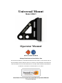
Universal Mount Model UM-01 Operator Manual NOTE TO INSTALLERS Always Read Instructions Before Use THE OPERATOR MANUAL CONTAINS INFORMATION RELATING TO THE PROPER USE OF THE UNIVERSAL MOUNT AND INCLUDES ALL PRODUCT AND WARRANTY INFORMATION. THIS DOCUMENT MAY ONLY BE REMOVED BY THE END USER. ENSURE USER MANUAL IS READILY AVAILABLE TO OPERATORS AT ALL TIMES. Head Rush Technologies Universal Mount Operator Manual P/N 00070045001 IMPORTANT SAFETY NOTICE CLIMBING IS A DANGEROUS ACTIVITY Failure by the installer or operator to heed any and all instructions, warnings, and cautions for the correct installation, operation, care, and maintenance of the Universal Mount may result in serious injury and/or death. The Universal Mount and associated equipment is designed and specified for use in the recreational climbing industry as a climbing anchor. Use of the Universal Mount for any purposes other than that intended by the manufacturer is not permitted. Owners and operators of the Universal Mount are responsible for the safety and supervision of any person using the Universal Mount and are required to undergo training in the correct installation and operation of the device and associated equipment prior to use. These instructions must be made readily available to the operator at all times. Prior to installation and use, all owners and operators must have read and shown to have understood all instructions, labels, markings, and safety information pertaining to the installation, operation, care, and maintenance of the Universal Mount, its component parts, and all associated hardware. Failure to do so may result in equipment damage, serious injury, and death. This manual does not cover the TRUBLUE Auto Belay system. Refer to the TRUBLUE Auto Belay Operator Manual. www.headrushtech.com – P/N 00070045001 1 TABLE OF CONTENTS WARRANTY CONDITIONS .............................................. 3 Customer Responsibility 4 DESCRIPTION ................................................................. 5 Specifications Universal Mount Parts 5 6 SAFETY INFORMATION .................................................. 7 Symbols Used in this Manual Read Before Installation and Operation Health and Safety Site Rescue Plan 7 8 8 8 UNPACKING.................................................................... 9 Precautions Receipt of the Universal Mount 9 9 INSTALLATION ............................................................. 10 Precautions Standards Mounting 10 10 12 OPERATION .................................................................. 14 Operator Training 14 INSPECTION AND MAINTENANCE ............................... 15 Service Life Weekly Inspection 15 15 MANUFACTURER DETAILS .......................................... 17 www.headrushtech.com – P/N 00070045001 2 WARRANTY CONDITIONS The Universal Mount is warranted against factory defects in materials and workmanship, excluding specific field replaceable wear parts, for a period of two (2) years from date of purchase. This warranty applies only to the original purchaser, and is contingent upon the owner/operator using and maintaining the device in accordance with the instructions, including the requirement to maintain regular inspection as described in all applicable manuals. THIS WARRANTY IS IN LIEU OF OTHER WARRANTIES, EXPRESS OR IMPLIED, AND ANY IMPLIED WARRANTY OF MERCHANTABILITY OR FITNESS FOR A PARTICULAR PURPOSE IS HEREBY EXPRESSLY EXCLUDED. The sole remedy for breach of this warranty, or for any claim in negligence or strict liability in tort, is the repair or replacement of defective parts at the discretion of the manufacturer. Parts claimed to be defective shall be returned to the factory, transportation prepaid, for inspection to determine to its satisfaction that said part(s) are defective. This warranty is null and void if parts other than genuine parts are used, or if any modifications or services have been performed on the device by anyone other than an authorized Head Rush Technologies servicing agent. This warranty does not cover damages resulting from normal wear and tear, abuse to the device, damage in transit, or any other damage beyond the control of Head Rush Technologies. Head Rush Technologies makes no warranties in respect to trade accessories or component parts which are not made by Head Rush Technologies. This warranty expressly excludes the replacement of specific field-replaceable wear parts. No person, agent, or distributor is authorized to give any warranty, other than the one herein expressed, on behalf of Head Rush Technologies, or to assume for it any liability pertaining to such products. Head Rush Technologies expressly disclaims any implied guarantee of merchantability, or claim as to whether the device is suited for a particular purpose. Purchaser agrees that Head Rush Technologies shall not be held liable to purchaser/operator for damages of any kind, including but not limited to, lost or projected profits, equipment down-time, or any losses considered to be caused by non-operation or servicing/recertification downtime of the equipment. www.headrushtech.com – P/N 00070045001 3 Customer Responsibility The following items are considered to be the responsibility of the customer and are therefore non-reimbursable under the warranty terms: Routine maintenance and inspection Normal replacement of service and wear items Replacements required because of abuse, misuse, or improper operation of equipment by the installer or operator Wearing or additional parts such as fasteners, straps, etc. Normal deterioration due to use and exposure This warranty is subject to the following requirements of this Operator Manual, manufacturer instructions, and advice given by authorized Head Rush Technologies service technicians. www.headrushtech.com – P/N 00070045001 4 DESCRIPTION The Universal Mount is a mounting device designed specifically for use as a climbing anchor. It is meant to be used on trees, poles, and climbing walls to provide an anchor point to mount a TRUBLUE® Auto Belay or other climbing anchor. The Universal Mount is suitable for climber weights up to 150 kg (330 lbs). To protect the longevity of the Universal Mount, installation, care, and use of the Universal Mount must be carried out in accordance with the instructions in this manual. Specifications Model: UM-01 Dimensions: 300 x 175 x 257 mm (11.8 x 6.9 x 10.1 in) Net Weight: 2.95 kg (6.5 lbs) Materials: Powder Coated Aluminium 6061-T6 Maximum Climber Weight: 150 kg (330 lbs) www.headrushtech.com – P/N 00070045001 5 Universal Mount Parts www.headrushtech.com – P/N 00070045001 6 SAFETY INFORMATION Symbols Used in this Manual The following safety symbols are used throughout this manual to highlight potential dangers. One or more precautions may be associated with practices and procedures described within this manual. Failure to adhere to the precautions highlighted can result in death, serious injury, and equipment damage. Ensure that you read and understand all operating procedures related to the working environment and task you are undertaking. DANGER Indicates a hazardous situation exists that, if not avoided, will result in death or serious injury. WARNING Indicates a potentially hazardous situation that, if not avoided, could result in death or serious injury. CAUTION Indicates a potentially hazardous situation that, if not avoided, may result in injury or equipment damage. NOTE Indicates an action that must be taken to ensure personal safety and prevent damage to property or equipment. CARE FOR THE ENVIRONMENT Take care to minimize impact on the environment when carrying out this procedure. www.headrushtech.com – P/N 00070045001 7 Read Before Installation and Operation WARNING Failure by the operator to heed all instructions, warnings, and cautions for installation and use of the Universal Mount and associated equipment can result in serious injury and/or death. Owners and operators of the Universal Mount are responsible for the safety and supervision of any person using this equipment. Owners and operators are required by the manufacturer to read, understand, and follow all instructions in this Operator Manual regarding the correct installation and operation of the Universal Mount prior to use. These instructions must be made readily available to the operators and users at all times. Prior to installation and use, all owners and operators must have read and shown to have understood all instructions, labels, markings, and safety information pertaining to the installation, operation, care, and maintenance of the Universal Mount, its component parts, and all associated hardware. Health and Safety Owners and operators must abide by all standards, international, federal, state and provincial laws, and any specific health and safety regulations pertaining to the installation and use of this product. Site Rescue Plan Owners and operators must have devised an emergency rescue plan for any climber in distress at all sites operating Universal Mounts. Operators must inform users of the Universal Mount of the procedures for rescuing a climber in distress prior to climbing. www.headrushtech.com – P/N 00070045001 8 UNPACKING Precautions LEAVE THIS OPERATOR MANUAL ATTACHED TO THE UNIVERSAL MOUNT UNTIL INSTALLATION IS COMPLETE The Operator Manual contains information relating to the proper use of the Universal Mount and warranty information. The Operator Manual may only be removed by the end user. Ensure this manual is readily available to Universal Mount users at all times. Receipt of the Universal Mount The Universal Mount is packaged in a recycled cardboard box containing: 1 x Universal Mount 1 x Operator Manual www.headrushtech.com – P/N 00070045001 9 INSTALLATION Precautions ALWAYS USE DESIGNATED MOUNTING POINTS AND METHODS Never install the Universal Mount using any part of the device apart from the designated mounting points. Incorrect mounting can result in death or serious injury. HARD IMPACTS MAY RESULT IN STRUCTURAL DAMAGE Dropping of, or hard impacts to, the Universal Mount can result in serious damage to mounting points and the structure and may compromise safety of operation. If the Universal Mount is subject to a hard impact, remove it from duty and return the mount to an authorized service agent for inspection. ALWAYS APPLY LOAD IN THE DIRECTION INDICATED The Universal Mount can be mounted in any orientation to accommodate a multitude of applications, but loads must only be applied in the direction indicated. The Universal Mount should not be subjected to off-axis loading. When used as a climbing anchor, the mount should be installed with the spine vertical and the mounting holes closest to the ground. Standards Prior to installation, all operators must be familiar with the requirements of all relevant standards for anchor points, hardware, and equipment used with the TRUBLUE Auto Belay and the Universal Mount. Anchor Points All anchor points and connectors used with the Universal Mount must conform to any federal and state requirements for such devices. Minimum requirements for anchor points must conform to the following safety standards: EN 12572 - Climbing wall anchor points EN 795 - Anchor Devices The location and anchor points for the Universal Mount should comply with the following: www.headrushtech.com – P/N 00070045001 10 Minimum load capacity of the anchor point(s)—10kN (2248 lbf) in expected directions of application. Anchor points should be of a suitable size to correctly install any mounting hardware. Secondary Connectors All secondary connectors and hardware used in the installation of the Universal Mount must be of compatible size, shape, and strength for the mounting point to which they are attached and conform to the following safety standards: EN 362 - Types of connectors for personal protection EN 12275 - Types of connectors for mountaineering Selecting a Location The Universal Mount is to be mounted at the top of the climbing route, tree, pole, or similar structure. Users tethered to the Universal Mount should not climb or operate above the mount. When selecting a location to install the Universal Mount, always ensure: The structure and/or anchor points have a minimum load capacity of 10kN (2248 lbf) and conform to all federal and state requirements for such devices. If straps are being used to anchor the Universal Mount, ensure any surfaces that are in contact or in close proximity to the straps are free of sharp edges or protrusions that may damage the strap. Note: Prolonged exposure to the elements will increase the risk of internal corrosion and degradation of any straps used to mount the Universal Mount. Always follow the manufacturers’ recommendations and instructions for associated equipment. www.headrushtech.com – P/N 00070045001 11 Mounting The Universal Mount can only be mounted using the methods and hardware described in this manual. When installing the Universal Mount, be aware of the following precautions: Anchor points must be capable of withstanding a minimum load of 10kN (2248 lbf) in the expected direction of load application. All connectors, hooks, D-rings, and shackles used to mount the Universal Mount and associated equipment must comply with all relevant standards. All secondary connectors must be of compatible size, shape, and strength to the mounting point to which they are attached. Mounting Points USE ONLY THE MOUNTING METHODS AND POINTS DESIGNATED IN THIS MANUAL Use only the correct mounting points designated for use with straps or bolts. Use of incorrect points can result in equipment damage. Strap Mounting The Universal Mount may be mounted using straps to avoid permanent installation, damage to trees, poles, or mounting surface. To install the Universal Mount with straps, use both slots located above the intersection between the spine and base. When using straps to mount the Universal Mount, be aware of the following precautions: Two (2) straps must be used for each Universal Mount. Each strap must be rated to a minimum working load limit of 14kN (3147 lbf) and comply with all relevant standards. Tighten the straps to the point where the mount cannot be pulled or deflected with the full force and weight of the heaviest user. The Universal Mount should not move under load and should be tested with non-human weights prior to use. The pole MUST have a minimum diameter of 10 inches to be used with this method. www.headrushtech.com – P/N 00070045001 12 WARNING Installation on smooth poles or poles without significant friction on their surface cannot use this method as the risk of slipping down the pole is too great. Only poles with surfaces that engage high friction between the strap and the mount can be mounted with this method. Bolt-Hole Point Mounting The Universal Mount may also be mounted using the designated bolt holes. When mounting with bolts, be aware of the following precautions: All bolts, nuts, washers, and hardware used for mounting are to be ½” (ASTM A307 Grade A or B) or M12 (Grade 4.6). Use of locking nuts (stover, nylock, etc.) or thread-locking compound is strongly recommended. Use no less than 4 fasteners to structural points, minimum 2 per side. Fasteners must be connected to a structural component per the anchor requirements listed above. www.headrushtech.com – P/N 00070045001 13 OPERATION Owners and purchasers of the Universal Mount are responsible for the safety and supervision of any person using this equipment and are required by the manufacturer to read, understand, and follow all instructions in this Operator Manual regarding the correct installation and operation of the Universal Mount prior to use. UNSAFE OPERATION Remove the Universal Mount from service immediately if there is any concern over its correct operation or user safety. Do not return the Universal Mount to service until it has been inspected and completed a recertification inspection and test by an authorized Head Rush Technologies service agent. Operator Training All personnel involved in the operation of the Universal Mount and supervision of the user must be trained and deemed competent in the following aspects of Universal Mount operation: Installation, use of attachment points, and attachment methods and hardware. Inspection, cleaning, and scheduled servicing of the Universal Mount and associated equipment. www.headrushtech.com – P/N 00070045001 14 INSPECTION AND MAINTENANCE Service Life The expected service life of the Universal Mount is equal to that of the structure in which it mounts to. The Universal Mount has been designed for use outside and in harsh environments with a wide range of temperature and weather conditions. If the mount is found to be damaged or worn during inspection, replacements are available from Head Rush Technologies and Authorized Service Centers. Weekly Inspection Safety Precautions The Universal Mount must be inspected weekly for overall condition to verify against acceptable wear. The weekly inspection may be completed with the Universal Mount in place or removed to a sturdy work table. Check fasteners monthly. Remove, inspect, clean, and reinstall fasteners at least annually, ensuring thread compound and/or locking nuts are replaced appropriately. Installations subject to saline or other harsh environments should perform inspections more frequently. Inspection Procedure Ensure adequate lighting and unrestricted access is available to permit a thorough inspection of all areas of the Universal Mount and associated equipment. 1. Clean any dust, dirt, or contamination of the Universal Mount and any fasteners with a clean cloth. DO NOT USE SOLVENTS OR ABRASIVES Clean with a cloth only. Do not use any cleaners, solvents, or abrasives on any part of the Universal Mount or associated equipment. 2. Visually inspect the mounting holes, welds, straps or fasteners, and general features for wear, impact damage, cracking, deformation or corrosion. Replace any damaged components or remove the Universal Mount from service. 3. If all components pass inspection, return the Universal Mount to service. www.headrushtech.com – P/N 00070045001 15 Wear Limits The Universal Mount may be subjected to wear on the mounting holes, bolt holes, strap slots, fasteners, or along the weld joint. If a component is found to be damaged or worn, immediately remove from service. Replacement parts are available from Head Rush Technologies and Authorized Service Centers. www.headrushtech.com – P/N 00070045001 16 MANUFACTURER DETAILS Return the Universal Mount to the manufacturer at the address shown below for any replacement or unscheduled service or repairs. Address: Head Rush Technologies 1835 38th Street Suite C Boulder, CO 80301 USA Contact Details: Phone: 877-565-6885 Phone: 720-565-6885 (international customers) www.headrushtech.com [email protected] www.headrushtech.com – P/N 00070045001 17 [email protected] 720-565-6886 | 877-565-6885