1
STANFORD ARTIFICIAL INTELLIGENCELABORATORY
MEMO AIM - 199
STAN-CS-73-398
IMAGECONTOURINGANDCOMPARING
BY
BRUCEG. BAUMGART
SUPPORTED BY
ADVANCED RESEARCH PROJECTS AGENCY
ARPA ORDER NO. 2494
PROJECT CODE3030
.
OCTOBER 1973
COMPUTER SCIENCE DEPARTMENT
School of Humanities and Sciences
STANFORD UNIVERSITY
STANFORD ARTIFICIAL INTELLIGENCE LABORATORY
MEMO AIM-1 99
OCTOBER 1973.
COMPUTER SCIENCE DEPARTMENT REPORT NO. CS-398
.-.
.
IMAGE CONTQURING AND COMPARING
Bruce G. Baumgart
ABSTRACT:
A contour image representation is stated and an algorithm for converting a set of
digital television irnages into this representation is explained. The algorithm consists of
five steps: digital image thresholding, binary image contouring, polygon nesting, polygon
smoothing, and polygon comparing. An implementation of the algorithm is the main routine
of a program called CRE; auxiliary routines provide cart and turn table control, TV
camera input, image display, and Xerox printer output. A serendip application of CRE to
type font construction is explained. Details about the intended application of CRE to the
perception of physical objects wili appear in sequels to this paper.
lc
c
CONTENTS:
c
Introduction.
I. The CRE data structure.
6
II. The CRE algorithm.
Ill. Using CRE.
IV. Using TVFONT.
Post scripts.
This research was supported in part by the Advanced Research Projects Agency
of the Office of the Secretary of Defense under Contract .No. DAHC 15-73-C-0435.
I
‘L
i
The views and conclusions contained in this document are those of the author and
should not be interpreted as necessarily representing the official policies, either
expressed or implied, of the Advanced Research Project Agency or the United States
Government.
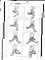
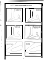
FI
GURE
1-
BABY oO!Jm O N A T U R N T A B L E .
INTRODUCTIOI\I.
The. (c\ct-onym CRE stands both for “Contour, Region, Edge”. CRE is a solution to
the p~01~l~n of finding c o n t o u r edges in a set of television pictures and of linking
corr~~:,por~tiiy cdgc~s from one picture to the next. The process is automatic and is
inf r:nCjecj to run wit bout human intervention. Furthermore, the process is bottom up;
there sire no <+ificant inputs other t1~a.n the given television images. The output of CRE
is a 2D contour map data structure which is suitable input to a 3D geometric modeling
progr*;ir-n.
b
The! overall design :o;rl for CRE was to build a region-edge finding program that
could t-)e applied to a sequence of television pictures and that would output a sequence
of line &swings Gt!lout having to know anything about the content of the images.
Furthermore it WC?G dcsircd that the line drawings be structured. The six design choices
that &tt-rrnined the character of CRE are:
c
I . Dumb vision I ather than model drivel) vision.
2. Multi itn;lge analysis rather t h;:in single image analysis.
3. Tot al imazc: struct urc imposed on t !cJ:c! finding; rather
than separate edge finder dnd irnabc analyzer.
4. /2LJt Okjt iC rat her t ban intcr,-,ctivc.
5. Fixed image window size rather than variable window size.
6. Machine language rather than higher level language.
L
I
The de!;i:;n ct-loices are ordered from ihe more strategic to the more tactical; the
firr;t i hrei; ctAccs being research strategies, the latter three choices being programming
Adol:\in: t hcsc cJc:;ipn choices lid to image contouring and contour map
t aclics.
st ruct ut 0:; ;irnilar to that of Krakauer[3] and Zahn[4].
L
e
L
The! first design choice does not refer to the issue of how model dependent a
finis;)& ;er~r;:l vision system will be (it will be quite model dependent), but rather to
t h r if,s I I:? Of how one should begin building such a system. I believe that the best
starting point c; are at the two apparent extremes of nearly total knowledge of a
par t icul:lr visur;ll world or nearly tot al ignorance. The first extreme involves synthesis
t by cornput c?t* s;-;raphics) of a predict cd 2D imngo, followed by comparing the predicted and
a per ceivc-Ed ic-,Ia$e for slight differences which arc expected but not yet measured. The
sc(:otd 1?Xt I’i‘illi!
involves onnlysinz pr.rcc,ivcd images into structures which can be readily
c o , iipat-f-4 for ncai’ cyu:Jity and measured for slight differences; followed by the
. conc.;it uctirm af a Z;D geomrtric 111ocM bf the perceived world. The point is that in both
. cast:; iirl;;:,;.:; ;1re c:ompclr~d, and in both cam: the 3D model initially {or finally} contains
*.
;pC~Cl fiC IIili’il;brical data on the geor;lL;try and physics of the particular world being looked
at.
3
-L-
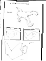
fl CURE 2 - B L O C K S C E N E O N A T U R N TAB1
-
,/------.
I--- --
-e
,*_----+--+
-- h
I-
J
The ::~ond design choice, of multi image anaylsis rather than single image analysis,
pro\: icjles (1 tl;isis for solving for c:)mera /positions and feature depths. The third design
choice SQIW:: ior rc7thcr avoidsj the problem of integrating an edge finder’s results into
an i ma:;c. Ey usin:: a very simple edge finder, and by accepting all the edges found, the
i rn;lzc: r;trcI!;ture ir; never l o s t . This design postpones the problem of interpreting
phot omct ric t adzes as physical edges.
i
That fourth choice is a resolution to write an image processor that does not
recjuires Gpc2t,l:it Or assist ancc or param& er tuning. The fifth choice of the 216 by 288
fixd window t;ize i; a sin that proved surprit:ingly expedient, it is explained later. A
variabl p window ver<iclii of CRE Gt ii;ri bcs, third:; and other simple fractions of its present
LvIt7dGw size ivt,/ill ]je cl-lade at ~of~le future date.
I
v-
i
The final desi;r;Tn choice! of usin: machit-ic ~XQKJ~~ was for the sake of implementing
node link kit a structures that are procc sc;ed 100 faster than LEAP, 10 times faster t ban
cornpi1i.d 1 19’ and thcit require significantly ICSS memory than similar structures in either
LISP or LEAP. Furthf~rmore machine code assembles and loads faster than higher level
lancua.o,es; ;ind n%ichine code can be extensively fixed and altered without recompiling.
It is my impression that CRE does not- raise any new scientific problems; nor does
it have tiny really new solutions to the old problems; rather CRE is another competent
video t*eQion i:dgr. finding program with its own set of tricks. However, it is further my
impression that the particular tricks for smoothitlg, nesting and comparing polygons in CRE
arc ot+:in;;l :IS prost-nrnming t cchniques.
The intended use of CRE is illuc;ir;rted by the sequences of turn table pictures on
p;~f:cs 1 a n d 3. The figures on page 5 illustrate the quality of contoured images over a
range of subject matter. Finally the application of CRE to typography is illustrated
below;
TOWS i/lock assisted me with the dcvclopment of the type font making program,
TVFGNT.
-4-
L
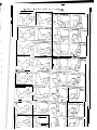
FI G U R E 3 - I NTENSI T Y C O P iTOUR N G O N A VARI E T Y v, ~uOJCL 1
nc Cl113 I I - h -
-
.
I
IL- /* J /-
’ i
I
L
-
-
*
II
s.
DA-T-A !.GTNJCTUCIE; L!ASICS.
The? two s*nc~ric data structures of CKE are arrays and nodes; there are five kinds
of 4rr4yr; i.,nd *eight k i n d s o f nods!::..
The node structures to be discussed are
impic:rnr?r~t~-cl (-6 scvcn word fixed sized blocks in a fashion usual to graphics and
si rnt-ll at i cm ;:I? into ocfuction to this technology can be found in Knuth [4]. The language of
implr.:tn:,nt;iliotl is PDI”- 1 0 rn;Icl;in!: code via the FAIL asscmblcr.
k-
i
I
A:.; ih! pm-y;.;t cxtlmpics of contoured images on page 5 illustrate, a notion that is
err-nph;-;t i~lly not in CRE, is that of a schematic line drawing. Although the CRE output can
be viewe{-! ;I; a collection of lines on ;11 display screen, people expecting a line drawing
rctldition c,f the civcn tclcvision pictur!: will be disappointed. A CRE picture is a simple
tr~insfor-t-n;,tion of the photometry, omeometry and topology of the original video image;
whet ?ilS the typicdl line drawing from a human illustrator is a representation of the
scc:nc without photometric inforrnation. On the other hand, the work of an artist such as
Peter Max; or a paint-by-the-numbers grid does resemble CRE output. This is not an
idIt coincidence but rat her a consequence of whether or not the artist is trying to
rcprcscnt photometric data by quantum lines.
The: ~!xpli?nation of CRE no&-3 I;tru&jrCC,J will be presented in three parts: first, the
SW~-YC~I I$~+ of I-IOC~I~~ will be t:)riefly expl~~in~d; second, the sub structures such as rings,
tret>i, ;!tvi Iik>ts \,+/ill t,e &scrib&; ,:ltld thirci, the node formats and their contents will be
c::<I )I ;ri r-\1-~rJ i II- I <J?tGil. Follcwin~ that \.vill 1~ an c:xlTl?nztion of the five at-rays in CRE. The
rec&t* is ~~~~arn~zd th3t this whole r;ub section (on data structure) is an elaborate shaggy
do:: st orq’ o f t~arnitl~ tlsmc’s and c-ielir~in~ things; all the action is to be found in the
following 9 lb section (on the algoti t hm).
DA l”A STRUCTUHE; KINDS OF NODES.
TIw ;NP ci$t kinds of CRE nodes: Vector, Arc, Polygon, Shape, Image, Level, Film
and Empty:
J. At the top of the structure is the film node, the film node is unique and serves
as an OGLIST from which all other node‘s may be reached. The film node embodies the
idea of ;I ;!iccc of celluloid film or a Icn$h of magnetic video tape. A film is a sequence
of i t-nages t akcn by the sarne camera of the same scene with only a small amount of
action bet ween images.
i
c
2. An image node represents the familiar two dimensional idea of a photograph or
an oi] n-3;b>tiq~r
,2urc 1\1f ‘a or to be exact a digital video image of 216 rows by 288 columns of
nurnbcrl; rl:;nE;in g from 0 for dark to 53 for bright. The image is formed by a thin lens and
is project& on a flat image plane. The idea of an image is so common that it is easy to
OVC-YIOO~C the wonder of sun light scattcrinz off of surfaces, refracting thru a lens, and
forr,lin;; a comp1e>: p;lt tern called a real image.
L
3. MCN the! image no& are the intensity contour levels, A contour level is a
b i n a r y ima:;e +hat r e s u l t s from thresholdine; a gray scaled image. So an image is
c o m p o s e d o f lev+3 and, in turn, G level is composed of polygons.
.
r
b
4. A Polygon node represents the idea of a contour loop which always closes
upon it sc!I f and HOERS not cross it self or any other contour, Contour loops are
approG-nated by a ring of vectors; hence, the term “polygon”. The contour polygons
always have at Ieast three sides and are simply connected.
5. Shape nodes contain data about one or two polygons. The data in a shape
node is not a positive rcprescntation of the notion of shape; but is rather the
pararnc.:tcrs of alignment that must be normalized out before shapes can be compared.
t
6. Vector nodc:s contain the locus of an image vertex; however since vectors
alway!; h~long to a polygon and always have two neighbors; their counterclockwise
ncigtitsot ic, considered to determine their vector direction,
7. ,4rc nodes are vectors that are made by the polygon smoothing routine; one arc
tyy;ic:jlly t~cpli~c t;e\-ler:;l v e c t o r s . When both arcs and vectors arc being discussed;
vcctot~ ‘ZINC rltrictly horizontal and vertical, whereas arcs may point in any direction,
2:. Ilmpty nodes arc ;~n ;hifact of tile fixed node size dynamic storage allocation
mcchani~in I.l:;cxd in CRE. Entities are made by taking empty nodes from an AVAIL list and
entities are killed by returnin 2 their node to the AVAIL list; there is no garbage collector,
but there is a space compactor.
-7-
DATA STRUCTURE; LINK AND DA-I-UM NAMES.
Nodes cont,rin eitlxr rxmerical data or pointers to other nodes; such node pointers
we ;tc t cI;J t i.t,i4i n t’- ;:dclt C-SLY and are called links. The positions within a node where a
linlc ir, r.~tor~-~~~ ,rrc? n;:lts~c-!d 2nd ;VC t.csr!rved for particular uses, In the table below the 1 1
link name) ;!nd 1 3 datum names are -introduced. The link names will always appear
capii J&d.
1 1 LINK NAMES:
CW clockwise
CCW coutlt er clockwise
l7AD parent of nod? up r7 free structure.
‘ON
4
desccndi~r~t of a node down a tree structure.
k.M Xl Greclk for inside, polygon wit hit\.
FXG Grc4< for out side, surrounding polygon.
/‘i L I-- aiternaie.
r”‘4~~~3J tq;.itive polygon.
PGGN
positive polygon.
-=.
NTIME negative in real time, into the past.
PTIME positive in real time, into Ihe future,
c
“’
t
t
t
13 LIA-I-Ubl NAMES:
Eool ean dat ums.
t ypc
reloc
type of node bits.
rellocation of no& bits.
L
Fixed point datums.
row
col
cnt rr;t
ncnt
row of image IOCLI:;.
column of imsge 10~~~~.
contr:lst of an ( ‘::;(:I, v(:ctor and arc,
number count, \q-i ocr:; uses.
z depth fro~rl c,imora lens center.
lq$h of pcrim&~r.
area in pixel unit :3.
motnent of inertia &oiIt X axis.
moment of inertia &c(ut ‘/ axis.
moment of inertia about Z axis.
product of inertia with respect
to the X and Y axes.
-8-
DA-T-A STRiJ(:T~JFIE; THE RINGS, TREES, LISTS AND ARRAYS,
CRE inputs
some of which <Ire
a film of im;i,;5
but only the final
structures arc:
::n irnrizc into an array called TVBUF; it makes the node structures,
temporary; and it out puts a final version of the structure representing
The tcmporsry structures are relevant to understanding the process;
structure i s relevant. to using CRE output. In summary, the important
FOUR RINGS.
I . Irn;t;;i? t ing of the film.
2, I .cvcl ring of an im,gc.
3. Poly:,on ring of i-1 level.
4. Vector ring of a polygon.
c
TWi) 1’1axS.
I . The tree of tktzs.
2. The tree of nested polygons.
i
TWO LISTS.
1 .=Time line lists.
2. The cimpty node list.
TEMU:PC>RAR‘i STRUCTURES.
1. Arc rings of polygons.
2. Fusion shape rings of levels.
FIVE ARRAYS.
1. ‘T-VWUF - 216 rows,
258 columns of 6 bit bytes,
2. PAC - 2 1 6rows,
28S columns of 1 bit bytes.
3. \/SEC; - 2lf 1 rows,
289 columns of 1 bit bytes.
4. KEG - 21 7 row5 28Z columns of 1 bit bytes.
5 SK) - 2 I 6 row!;, 289 coltmw o f 1 8 bit bytes.
The-+ i:; on? film node. ‘The film is composed of a ring of images. Each image is
9f I~~vr.l’;. Each lcvcl is composed of a ring of polygons. Each
poij~ :;r)n
i5 r.omp~~~ed of a ring of \/ector.s. The ring structures are implemented with the
fotv- links t>,im 1:J DA13, SiiN, CW Lnc” CCW. The rings are headless only in the sense that
;;I! i tic F I ( ‘I’il;? r-it :3 of r3 riri r: are brothers; a pointer to the head of a ring is stored in the
&Ai3 irrk of t Ld?ctl elctilent. The DAD of the film node is NIL; and NIL is an 18-bit zero.
T/W iin;)l Wd of ;,I1 vector nodes is ijtso NIL. The DAD and SON links form a tree of
rir-qs.
c:r17p(; 3syl rlf r:~ I-iry
DA 17, STRlJCTUKE: THE RINGS, TREES, LISTS AND ARRAYS.
Besides the tree of rings, there is the tree of nested polygons. The nested
polygon tree i-d implemented with the four links named ENDO, EXO, NGON and &ON. The
E%O of a polygon points at its surroundin polygon. The END0 of a polygon points at one
of the polygons that may be enclaved within the given polygon; and the NGON and PGON
links form ;I ring of polygons that have the same EXO polygon,
The time line lists run thru arc and polygon nodes. In the simple case, the time
linr! links rjf (1 polygon point to a cowe.pm-jing polygon in the image previous (NTIME) or
subc~quent i PT1Ml-S) of the current polp;on; the correspondence being that the time
polyson is i93ctly the smx~ it~tm~ity at nc~rly the same location, orientation, and size as
the +Jc:n l~Q~,on. In the! cze of t’olyzon fusion, the time line link of a polygon points to
a time polygon of which the given polygon becomes a part. In the case of polygon
fis:;ion, i II<! time line link of a polygon point-3 to only one the pieces into which the given
poly;;on splits.
The time line links of an arc vector point to a corresponding arc vector in the
image previous --.or subsequent of the current arc vector. The polygons of arc vectors
mated in time are t hemsetvos mated in time; because after polygon time tine links have
been made, one polygon is temporarily t ransl&zd, rotated and dilated so as to have the
same Iarnina inertia tensor as its mate; that is the locus of the arc vectors of one polygon
arc t emporarity qtt ered; then the correspondin: arc vectors are found and their time line
linka:c3s at-f made.
The empty node list is maintained in the CCW link positions; the last empty node
contarns a zero link. All nodes are explicitly made from and killed to the empty node Ii&
by the subroutines MKNODE and KLNODE.
1
The arc ring of a polygon is just like a vector ring except that the pointer to it is
:t orc:d in the ALT link of the polygon, white the polygon has both a ring of vectors and a
ring of c’irc:,.
L
.
The fusion shc;pc: ring of a intensity lev4 runs thru the CW and CCW links of
shape nodes cind is pointed at by the ALT link of the level. Fusion shape nodes are the
sh:ipes gencrclted to represent pairs of polygons unmated in time.
-lO-
DATA STHUCTUHE: TYPE BITS.
Each node has a word reserved for a boolean vector of 36 values, or bits. The
first eighteen bits are called the type b its and are individually named as follows:
LVE:SI EIT
1
only 2
3
L
4
5
for
6
poly~onr-;
only 7
8
9
b
10
L
modify 1 1
.
r
L
SOUEIT
westw-:jrd vector.
southward vector.
eastward vector.
northward vector.
KSE
NFISS
NEXCT
N-TIME polygon fusion.
NTIME polygon fission.
NTIME polygon exact match.
PFUSE
PFISS
PEXCT
PTIME polygon fusion.
PTIME polygon fission.
PTIME polygon exact match.
HOLBIT
ARCBIT
Hole polygon bit.
Arc vector bit.
12
13
14
SBIT
VBIT
PBIT
Shape node bit.
Vertex node bit.
Polygon node bit.
15
16
LBIT
ICIT
17
FBI-I
Le\/cl node bit,
Image node bit.
Film node bit.
kind
.
-
e
The first four bits WESUIT, SOUBIT, EASC>IT and NORBIT apply only to vectors and
indic ;tt c the! dkction o f t h e v e c t o r . The next s i x b i t s NFUSE, NFISS, NEXCT, PFUSE,
PFII;:;, F’EXCT dt
i ’ e set by the polygon comp;rt*e routine to indicate the kind of time mating
folIr)ij; whc.t c) N and f mt??lln rq&c! time or ljostivc time linkage; fusion means that the
e;ivc:n polygon and ;jnother polygon fuse to form the time polygon, two into one; fission
. means the g&n polygon splits, one into two; and exact means that the given polygon
matchr, once for one with its time polygon.
The rlext two bits HOLOIT and ARClIT indicate distinguished polygons and vectors
respclctivt2ly. Only one of the last six bits: SBIT, WIT, PBIT, LBIT, BIT and FBiT may be
on it) 21 node. These bits indicate the node’s type.
- 11 -
DATA STRUCTURE: RELOCATION BITS.
The next ei,nhteen bits are called the rel,oc bits and indicatk whether or not a link
is stored in a particular position of the node. The relocation bits are used to compact
the CRE node space for output.
..
L
1
L
L
18
19
20
unuxd
CAR(WORDOj
CDR( WORDO)
21
22
23
unused
CAR(WORD1)
CDRi WORD 1)
24
25
26
unused
CAR(WORD3j
CDR( WORD3)
27
28
29
unused
CAR(WORD4)
CDR( WORD4j
30
31
32
unused
CARiWORDSj
CDR! WORD5)
33
34
35
lJnur,cd
CAR{ WORD6)
CDRiWORDG)
The CAR of a word is the left half. The CDR of a word is the right half. in the
node diqr-lms the relocation of each word is indicated directly to its right as 0, 1, 2 or 3
meaning no relocation, left only, right only, and relocate both halves, respectively,
- 129
t-
1. VECTOR K 2. ARC NODE FORMAT.
cw
IJnr-cI
il
--l-lot- cl
1
--. 1.ic1r cl
71
L_
L
I.IC~f‘ r-l
3
-----I JOI rl
.
ccw
I h
d
DAD
------7n7
-. a r c or vector
----____ -__-- ^-__ - _ -~-I_
reloc
tYPe
33 0003
po I ggon
r PI-I
0000.00
---__-_l____l_
cntrst
4
--- .- .I.lOf‘Ci
5
---- -.-Ilord
G
L
1
vecto r rrng
ccl
0000.00
--.--._ _ .._
0
rlcrl!
I eng t h
0
0
zdepth
NT I t1E
3
time I ine
PJIME
3
I
The format of vectors and arcs is identical. Inside CRE the term “vector” has the
connotation of being strictly a horizontal or vertical generated by the cant ouring step;
whereas an arc is a vector generated by the smoothing step. Vectors contain the
fundamental geometric datum of an image locus. The image locus is stored in the
halfword datums named row and cot, which contain the row and column of a point in units
l/64 of a pixel. (A “pixel” is a “picture element”). Vectors and arcs also contain the
photometric datum of edge contrast.
i
c
Vectors always belong to a polygon node, a pointer to the polygon of each vector
is stored in the link named DAD; as members of a polygon the vectors form a loop which
is always connected so that each vertex has a neighboring vertex in the clockwise and in
the counter clockwise directions about the polygon’s perimeter; these perimeter pointers
are stored in the link positions named CW and CCW. Vectors never cross, arcs cross on
occassions but can be fixed.
c
e
The ncnt datum of arcs and vectors contains their length. The time line links,
NTIME and PTIME, may point to a corresponding arc or vector in the image previous or
subsequent to the current image. (The zdepth datum contains a positive number
indicating dislance from the camera’s image plane; the tdepth computation is not properly
- implemented as of May 1973L
- 13-
\/
3. POLYGON NODE FORMAT.
r I ng
SON
*. 1st vector
-reloc
33 3233
.-----Em
00 I vgon surround me
ncn t
nmber of s i cles
rc
------TGON
nest s i t; po I ygon
I ine
FT I flE
tvery polygon belongs to a level pointed at by the DAD link; the ring of polygons
of a level is formed in the CW and CCW links; the son of a polygon is its first vector (or
arc after the polygon has been smoothed) and that first vector has the upper left most
locus of any vector of the polygon.
The ENDO, EXO, NGON, PGON are used to form the nested polygon tree. Every
polygon IIS non-NIL NGON and PGON links; the trivial case being that the polygon points
at it self twice. Every polygon except one, the outer border polygon, has a non-NIL EXO
link. Every polygon that surrounds one or more other polygons has a non-NIL EN00 link.
The ALT link position of a polygon temporarily points to the first arc of a polygon
during smoothing when a polygon has both vectors and arcs. The final contents of the
ALT link is a pointer to the shape node of the polygon. The ncnt datum indicates the
number of sides of the polygon.
The time line of polygons runs thru the NTIME and PTIME links which point either
to c’i nearly exact match of a polygon; or to a fusion polygon of a two for one match; or
to one of the two fission parts of a one for two match; {to find the other fission part, the
tjme links of the vectors must be scanned).
- 14-
4. SHAPE NODE FORMAT.
..-.- _-
-.
L Ior cl
f us i on sh
~.- --perni
area
0
--l~lor cl
1
t Y li;’
---r OLI
0000.00
L
-I-lot- cl
PXY
4
produr, t 0 f i net- t i a
---_11or d -NC;ONY
fusion polygon
5
-.----- mxx
Ilord
G
X - a x i s monien t
___--
i
reloc
30 0030
---co I
0000.00
nizz
Z-ax i 5 moment
lT.37
main polygon
Y-ax i “:‘k!onien t
--.
L
The shape node contains the data necessary for normalizing two polygons so that
only their shapes remain. In particular, the row and col of a shape node is the center of
mass of the polygon; area is the area; perm is the length of perimeter; and mxx, myy,
mzz, pxy is the polygons inertia tensor (frorn which the principle angle of orientation can
be computed). When given two shapes, the centers of mass may be aligned; the
principle angles may be align; and the areas (or perimeter) of the two may be normalized.
i
.
There are two kinds of shapes: polygon shapes and fusion shapes. Polygon shapes
correspond to a sing-le polygon pointed at by the PGON link. The CW, CCW and NGON
links of a polygon shape ;,re NIL. Fusion shapes are temporary nodes belonging to a
level as a ring thru CW and CCW. Fusion shapes correspond to the summation of two
unmated polygons which are pointed to by the NGON and PGON links. The expressions
relating to the inertia tensor and to fusion summation are given in the section on polygon
comparing.
T h e datums named perm, area, pxy, mxx, myy, mzz contain the left half of a
POP-i 0 floating number. (Technical note: haif of a floating number has 9 bits of
. prttcision ;lnd should be expanded to full word by using the (mirabile dictu !) HLLE
: instruction in order to avoid an illegal floating zero caused by truncating numbers Jjke
-1023.0; in CRE, only the product of inertia will ever be negative).
- 15-
5. LEVEL NODE FORMAT.
---cw
CCW
level ring
---- - -__... __.I -___ -- _
-. . - - - - - WEJ
LtALJ
i fuage
I
-
1st polygon
.
3
3
relOC
33 0200
---
-T--
ALT
(1st fusion shape)
L
L
b-
.
ncn t
threshold cut level
0
2
Be-
0
--a
0
--
t
i1
Every level belongs to an image pointed to by the DAD link; the ring of levels of
an image is formed in the CW and CCW links; the son of a level is its first polygon and
that first polygon is the upper left most polygon of the level.
The ncnt
between -1 and
with four sides.
that every point
which is blacker
datum of a level contains its threshold cut value, which is an integer
63. The -1 level is always generated, and it contains a single polygon
The -1 level’s polygon is called the border polygon; the fiction being
beyond the edges of the television picture has an intensity value of -2,
than black.
L
The ALT link of a level contains a temporary pointer to that level’s ring of fusion
shapes during polygon compare time mating.
L
- 160
6. IMAGE NODE FORMAT.
I4ord
0
mr d
1
cw
ccw
I
image ring
DAD
film
twe
3
-
-----TOY
1st level
..
--reloc
33 0000
--a
-___I_
-mm
c
I
3
0
0
---
0
-mm
0
Every image belongs to the film pointed to by the DAD link; the ring of images of
the film is formed in the CW and CCW links; the son of an image is its first level and that
first level is the -1 intensity cut level of the image.
L
.
L
Although an affront to common sense, the counter clockwise direction about the
image ring is positive or later in time and the clockwise direction is negative or earlier in
time. I achieved this curio by consistently adhereing to the mathematical convention of
counter clockwise as. positive; and a day came when counter clockwise around a ring of
real time events was represented in the same manner as counter clockwise around a
polygonal ring of edges.
1
All the empty space in the image node is reserved for camera specification data.
1
- 17-
7. FILM NODE FORMAT.
ccw
I-IOt-Cl
1st empty
1
-----TON
1st image
3
0
l,J u I’ ri
1
i-jut- ci
2
---T$J
..
reloc
33 0000
L
0
0
0
i
0
The film -node is unique; it is the first node in a CRE output file; the SON of film is
its first image; the DAD of a film is NIL; the CCW of a film is a pointer to the 1st empty
node; however, because the nodes are compacted for output and then relocated with
respect to the film node; the final empty node pointer indicates the number of words of
data in the CRE file.
- 18-
8. EMPTY NODE FORMAT.
_I_-
ccw
1.13r cl
0
--
1
avai I
uorrl
1
LJot- cl
3
c
-Il(?r- rl
3-’
..--. _
Llf,I f-l
4
L
0
type
reioc
00 0000
0
--.
0
0
--.-..__
1-J 0 I’ 1:)
G
-
t-
1
0
The list--of empty nodes is maintained in the CCW link postion; the last empty node
contains a zero or NIL link. At present all the other words of an empty node are zero,
FIGURE SHOWING RASTER STRUCTURE.
:
L
NORTH
grid point R,C
0H S E C
0
R,C+l
.
‘--L,. WEST
K iG
H+l,C
- - - - - - - - -------___-__
0
PIXEL(R,C)
SOllTH
:
- 19-
EAST-+-w
DATA STRUCTURE: IMAGE ARRAYS.
As mentioned before, there are five arrays in CRE: TVBUF, Television Buffer; PAC,
Picture Accumulator; VSEG, vertical segments; HSEG, horizontal segments; and SKY,
background sky blue array. The dimensions are;
FIVE ARRAYS.
1. TVBUF
2, PAC 3. VSEG
4. HSEG
5. SKY -
L
c
L
c
- 216
288 columns of 6 bit bytes.
rows,
216 rows,
288 columns of 1 bit bytes.
- 216rows,
289 columns of 1 bit bytes.
- 217
rows,
288 columns of 1 bit bytes.
216rows,
289 columns of 1 8 bit bytes.
Inside CRE, the video image size was fixed at 216 rows of 288 columns of 6 bits
per pixel. My original idea was to write a vision operator that would be applied on a
small fixed sized window; so I have had windows 2 by 2; 2 by 3; 4 by 9; 32 by 36; 72
by 96; and 216 by 288. That is 216=2*2*2*3*3*3 and 288=2$:2+2*2*2*:3*:3. Having a
fixed window size avoids a morass of word packing, array allocation and window splicing.
Having a window size constructed out of powers of 2 and 3 simplifies what word packing
is required and allows me to do area and space computations in my head.
The image arrays of CRE are of course two dimensional with the coordinates in
row and columns. Row number increases going down image, in the negative Y axis
direction, which is also called the direction south. Column numbers increase going right
on the image, in the positive X axis direction, which is also called the direction east.
Video picture elements, or “pixels” are thought of as expressing the intensity of a
square cell; the cells are numbered from 0 to 215 rows, 0 to 287 columns; the number
of a ceil is the grid locus of its upper left (northwest) corner; the center locus of a cell
is at (row+1/5,col+1/2). A pixel cell is surrounded by four segments; the horizontal
segments are numbered 0 to 216 rows, 0 to 287 columns; the number of an HSEG is the
grid locus of its left (west) end point. The vertical segments are numbered 0 to 215
rows, 0 to 288 columns; the number of a VSEG is the grid locus of its upper (north) end
point. These conventions are suggested in the diagram at the bottom of page 19.
- 20 -
THE ALGORITHM: INTRODUCTION.
CRE consists of five steps: t hresholding, contouring, nesting, smoothing and
comparing. Thresholding, contouring and smoothing perform conversions between two
different kinds of images. Nesting and contouring compute topological relationships within
a given image representation. In summary the major operations are:
..
MAJOR OPERATION.
OPERAND.
RESULT.
1.
2.
3.
4.
5.
6-BIT-IMAGE,
1 -BIT-IMAGES,
VIC-IMAGE,
VIC-IMAGE,
IMAGE (9; FILM,
1 -BIT-IMAGES.
VIC-IMAGE.
NESTED-VIC-IMAGE.
ARC-IMAGE.
FILM.
THRESHOLDING:
CONTOURiNG;
NESTING:
SMOOTHING:
COMPARING;
t
Although the natural order of operations is sequential from image thresholding to
image comparing; in order to keep memory size down, the first four steps are applied
one intensity level at a time from the darkest cut to the lightest cut (only nesting
depends on this sequential cut order); and comparing is applied to whole images.
-=.
i
L
'i
The illustrations on pages 21 and 23 show an initial video image and its final
smoothed contour image; the illustrations immediately below and on page 24 the
corresponding intermediate sawtoothed contour images. The illustrated images are each
composed of seven intensity levels, and took 16 seconds and 13 seconds to compute
respectively (on a PDP-10, 2usec memory). The final CRE data structures contained 680
and 293 nodes respectives, which comes to 2K and 4.5K words respectively; the initial
video image requires 10.2K words.
FIGURE: PUMP SAW TOOTHED CONTOURS.
i
- - ---- - L
-k
-.____--I_----------I__-.
.
__-_
_
_---I_--
_-.---1_1--
FI G U R E 5 - B L O C K S C E N E V I DE0 AND SM3OTH C O N T O U R S .
c
- 23 -
-----__-_.__-_
1. THRESHOLDING.
Thresholding, the first and easiest step, consists of two subroutines, called
THRESH and PACXOR. THRESH converts a &bit image into a l-bit image with respect to
a given threshold cut level between zero for black and sixty-three for light. All pixels
equal to or greater than the cuf, map i.pto a one; all the pixels less than the cut, map into
zero. The resulting 1 -bit image is stored in a bit array of 216 rows by 288 columns
(I 728 words) called the PAC (picture accumulator) which was named in memory of
McCormick’s ILLIAC-Ill. After THRESH, the PAC contains blobs of bits. A blob is defined
as “rook’s move” simply connected; that is every bit of a blob can be reached by
horizontal or vertical moves from any other bit without having to cross a zero bit or
having to make a diagonal (bishop’s) move. Blobs may of course have holes. Or
equivalently a blob always has one outer perimeter polygon, and may have one, several
or no inner perimeter polygons. This blob and hole topology is recoverable from the CRE
data structure and is built by the nesting step.
L
L
b
t
I
Next, PACXOR copies the PAC into two slightly larger bit arrays named HSEG and
VSEG. Then the PAC is shifted down one row and exclusive OR’ed into the HSEG array;
and the PAC is shifted right one column and exclusive OR’ed into the VSEG array to
compute’ the horizontal and vertical border bits of the PAC blobs. Notice, that this is the
very heart of the “edge finder” of CRE. Namely, PACXOR is the mechanism that converts
regions into edges.
I
t
.
- 24 -
FI GURE 6 - SAW TOOTH DEKI NKI NG I LLUSTRATED.
1
rt
SAW TOOTHED
f
DEKI NKED
c
L
c
I--”
/
SMOOTHED
SAW TOOTHED &
DEKI NKED
II
2. CONTOURING.
Contouring, converts the bit arrays HSEG and VSEG into vectors and polygons,
The contouring it self, is done by a single subroutine named MKPGON, make polygon.
When MKPGON is called, it looks for the upper most left non-zero bit in the VSEG array.
If the VSEG array is empty, MKPGON returns a NIL. However, when the bit is found,
MKPGON traces and erases the polygonal outline to which that bit belongs and returns a
polygon node with a ring of vectors.
c
To belabor the details (for the sake of later complexities); the MKGON trace can
go in four directions; north and south along vertical columns of bits in the VSEG array, or
east and west along horizontal rows of the HSEG array. The trace starts by heading
south until it hits a turn; when heading south MKPGON must check for ‘first a turn to the
east (indicated by a bit in HSEG); next for no turn (continue south); and last for a turn to
the west. When a turn is encountered MKPGON creates a vector node representing the
run of bits between the previous turn and the present turn. The trace always ends
heading west bound. The outline so traced can be either the edge of a blob or a hole,
the two cases are distinguished by looking at the VIC-polygon’s uppermost left pixel in
the PAC bit array.
c
There are two complexities: contrast accumulation and dekinking. The contrast of
a vector is defined as (QUOTIENT (DIFFERENCE (Sum of pixel values on one side of t.he
vector){ Sum of pixel values on the other side of the vector}) (length of the vector in
pixels)j. Since vectors are always either horizontal or vertical and are construed as
being on the cracks between pixels; the specified summations refer to the pixels
immediately to either side of the vector. Notice that this definition of constrast will
always give a positive contrast for vectors of a blob and negative contrast for the
vectors of a hole.
e
The terms “jaggies”, “kinks” and “sawtooth” all are used to express what seems to
be wrong about the lowermost left polygon on page 25. The problem involves doing
something to a rectilinear quantized set of segments, to make its linear nature more
evident. The CRE jaggies solution (in the subroutine MKPGON) .merely .positions the
turning locu s diagonally off its grid point alittle in the direction‘ (northeast, northwest,
sout hwcst or sout beast) that bisects the turn’s right angle. The distance of dekink
vernier positioning is always less than half a pixel; but greater for brighter cuts and less
for the darker cuts; in order to preserve the nesting of contours. The saw toothed and
the dekinked versions of a polygon have the same number of vectors. l am very fond of
t-his dekinking algorithm because of its incredible efficiency; given that you have a north,
south, east, west polygon trace routine (which handles image coordinates packed row,
column into one accumulator word}; then dekinking requires only one more A D D
instruction execution per vector !
- 26 -
3. NESTING.
\
The nesting problem is to decide whether one contour polygon is within another,
Although easy in the two polygon case; solving the nesting of many polygons with
respect to each other becomes n-squared expensive in either compute time or in .
memory space. The nesting solution in -‘CRE sacrifices memory for the sake of greater
speed and requires a 31K array, called the SKY.
CRE’s accumulation of a properly nested tree of polygons depends on the order of
threshold cutting going from dark to light. For each polygon there are two nesting steps:
first, the polyg,on is placed in the tree of nested polygons by the subroutine INTREE;
second, the polygon is placed in the SKY array by the subroutine named JNSKY.
The SKY array is 216 rows of 289 columns of 18-bit pointers. The name “SKY”
came about because, the array use to represent the furthest away regions or
background, which in the case of a robot vehicle is the real sky blue. The sky contains
vector pointers;--and would be more efficient on a virtual memory machine that didn’t
allocate unused pages of its address space. Whereas most computers have more
memory containers than address space; computer graphics and vision might be easier to
program in a memory with more address space than physical space; i.e. an almost empty
virtual memory.
Li
The first part of the INTREE routine finds the surrounder of a given polygon by
scanning the SKY due east from the uppermost left pixel of the given polygon. The SON
of a polygon is always its uppermost left vector. After INTREE, the INSKY routine places
pointers to the vertical vectors of the given polygon into the sky array.
1
e
L
The second part of the INTREE routine checks for and fixes up the case where the
new polygon captures a polygon that is already enciaved. This only happens when two
or more levels of the image have blobs that have holes. The next paragraph explains
the arcane details of fixing up the tree links of multi level hole polygons and the box
following that is a quotation from the appendix of Krakauer thesis [3] describing his
nesting aigorit hm.
- 27 -
3. NESTING.
Let the given polygon be named Poly; and let the surrounder of Poly be called
Exopoly; and assume that Exopoly surroundc3 Jeveral
c
enclaved polygons called “endo’s”,
which are already in the nested polygon tree. Also, there are two kinds of temporary
lists named the PLIST and the NLIST. There is one PLIST which is initially a list of all the
END0 polygons on Exopoly’s END0 ring. Each endo in turn has an NLIST which is initially
empty. The subroutine INTREE re-scans the sky array for the polygon due east of the
uppermost left vector of each endo polygon on the PLIST, (Exopoly’s END0 ring). On
such re-scanning, (on behalf of say an Endol), there are four cases:
L
s
L
I
I
‘,
IL
1. No change; the scan returns Exopoly;
which is Endol’s original EXO.
2. Poly captures Endol; the scan returns Poly indicating
that endol has been captured by Poly.
3. My brothers fate; the scan hits an end02 which
is not on the PLIST; which means that endo2’s EXO is valid
and is the valid EXO of endo 1.
4. My fate delayed; the scan hits an endo which is still
on the P&&T; which means that endo2’s EXO is not yet
valid but when discovered it will also be Endol’s EXO;
so Endol is CONS’ed into Endo2’s NLIST.
When an endo polygon’s EXO has been re-discovered, then all the polygons on
that endo’s NLIST are also placed into the polygon tree at that place. All of this link
crunching machinery takes half a page of code and is not frequently executed.
..
L
-
KRAKAUER’S
_ ^ NESTING
_ _--._ - _ - _-_ALGORITHM.
___ _-. - ._
“lhr I ,nil?P 11 FP , 5 ‘)rrlr’r nl cd I,nP lhre+hold
Irvrl al H t lmer startlng at thr
III~,Iw .t Ir~vvl fhranch 1 lpr.1.
nl r.wh 1~~1. the- rnage IC, s c a n n e d , a n d t h e points E&OVP
I ” a ..‘I nt I h Iw- r-ny .
f Iw 1 IIf v-J111 1 d
,l P ln.1, c I’d
This scat& nrra~
I S then
scanned for
I Ink
I . F.
subsri o
f Al a t
t h e prevlcus level 1
b a c k ylolnters in thP s c r a t c h nrruy
If a clr~~~l end , ~1 rcachPd ( n o mr~r(r
nl thr r o o t .
t ~111 he R
- 28 -
part
011 point+ uhlch cam b e r e a c h e d
o f this t r e e . ”
FI GURE 7 - SMOOTHI N G A N D A R C MAKJ N G .
4. SMOOTHING.
In CRE the term “smoothing” refers more to the problem of breaking a manifold
(polygon) into functions (arcs), rather than to the problem of fitting functions to measured
data. The smoothing step, converts the. polygons of vertical and horizontal vectors into
polygons of arcs. For the present the term “arc” means “linear arc” which is a line
segment. Fancier arcs: circular and cubic spline were implemented and thrown out
mostly because they were of no use to higher processes such as the polygon compare
which would break the fancier arcs back down into linear vectors for computing areas,
inertia tensors or mere display buffers.
Smoothing is applied to each polygon of a level. To start the smoothing, a ring of
two arcs is formed (a bi-gon) with one arc at the uppermost left and the other at the
lowermost right of the given vector polygon. Next a recursive make arc operation,
MKARC, is is appled to the two initial arcs. Since the arc given to MKARC is in a one to
one correspondece with a doubly linked list of vectors; MKARC checks to see whether
each point on the list of vectors is close enough to the approximating arc. MKARC
returns the given arc as good enough when all the sub vectors fall within a given width;
otherwise MKARC splits the arc in two and places a new arc vertex on the vector
vertex that was furthest away from the original arc.
The two large images in figure-7, illustrate a polygon smoothed with arc width
tolerances set at two different widths in order to show one recursion of MKARC. The
eight smaller images illustrate the results of setting the arc width tolerance over a range
of values. Because of the dekinking mentioned earlier the arc width tolerance can be
equal to or less than 1.0 pixels and still expect a substantial reduction in the number of
vectors it takes to describe a contour polygon.
L
b
i
A final important smoothing detail is that the arc width tolerance is actually taken
as a function of the highest contrast vector found along the arc; so that high contrast
arcs are smoothed with much smaller arc width tolerances than are low contrast arcs.
After smoothing, the contrast across each arc is computed and the ring of arcs replaces
the ring of vectors of the given polygon. (Polygons that would be expressed as only two
arcs are deleted).
1
- 30 -
t
Fi GURE 9 - POLYGON COMPARE AND LI NK.
FI G U R E 9A.
I-
FI G U R E 98.
.--_ -1.
---_
F1 G U R E 9C. ----.
a
FI G U R E 9 0 .
0
5. COMPARING.
The compare step of CRE, CMPARE, connects the polygons and arcs of the current
image with corresponding polygons and arcs of the previous image. CMPARE solves the
problem of correlating features between two similar images and is composed four sub
sect ions:
1. make shape nodes for polygons.
2. compare and connect polygons one to one.
3. compare and connect polygons two to one.
4. compare and connect vertices of connected polygons,
5
First, the shape nodes of all the polygons of an image are computed. The shape
node contains the center of mass and the lamina inertia tensor of a polygon. The laming
inertia tensor of a polygon with N sides is computed by summation over N trapezoids.
The trapezoid corresponding to each side is formed by dropping perpendiculars “up” to
the top of the image frame; each such trapezoid consists of a rectangle an a right
triangle; since the cc.ides of polygons are directed vectors the areas of the triangles and
rctct ;Ingles wn be arranged to take positive and negative values such that a summation
will &scribe the interior region of the polygon as positive. The equations necessary for
computing the -tarnina inettid tensor of a polygon are collected in a table in the
postscripts to this paper and were derived by using Goldstein’s Classical Mechanics [ 11
as a reference. The meaning of the inertia tensor is that it characterizes each polygon
by a rectr-lngle of a certain length and width at a particular location and oriention; and of
further importance such inertia tensors can be “added” to characterize two or more
polygons by a single rectangle. It is the lamina inertia tensor rectangles that are actually
compared by CRE.
c
L
b
-
Second, all the shapes of the polygons of one level of the first image are
compared with all the shapes of the polygons of the corresponding level of the second
image for nearly exact match. The potentially (M*N/2) compares is avoided by sorting
on the center of mass locations. In CRE, which is intended for comparing sequences of
pictures of natural scenes; match for center of mass location is tested first and most
strictly, followed by match for inertia. Pointers between matching polygons are placed in
the time link positions of the polygon nodes and the polygons are considered to be mated
in time.
- 32 -
5. COMPARING.
Third, all the unmated polygons of a level are considered two at a time and a
fusion r,hapc node for each pair is made. The potentially (N*N/2-N) fusion shapes are
avoided because there is a maximum possible unmated inertia in the other image; if there
are no unmated polygons in one image then the extra polygons of the first image can be
ignored. In the event where there are unmated polygons in corresponding levels of the
two images, the fusion shapes of one are compared with the polygon shapes of the other.
The fusion (fission) compare solves the rather nasty problem, illustrated in figures 9A
and 9B of linking two contour polygons of one image with a single contour polygon in the
next image.
Fourth, the vertices of polygons mated in time are compared and mated. To start
a vertex compare, the vertices of one polygon are translated, rotated and dilated to get
that polygon’s lamina inertia tensor coincident with its mate (or mates). ConceptualIy,
each vertex of one polygon is compared with each vertex of the other polygon(s) and
the mutually closest vertices (closer than an epsilon) are considered to be mated.
Actually the potential (N*M) compares is avoided by a window splitting scheme similiar to
that used in hidden line elimination algorithms (like Warnock’s),
t
-=.
i
1
t
The results of vertex compare and mate are illustrated in figures 9A and 90; the
compare execution takes less than a second on images such as the pump, blocks, and
dolls that have appeared in this paper. The applications of this compare might include
the aiming of a pixel correlation comparator (such as Quam’s); recognition and location of
an expected object; or the location and extent of an unknown object. It is this latter
application that will be described in my forthcoming thesis.
c
2
- 33 -
III. USING CRE.
A.
6.
C.
D.
iL .
‘1
PRIMER ON RUNNING CRE.
TELETYPE COMMANDS.
SAIL INTERFACING.
LISP INTERFACING.
PRIMER ON RUNNING CRE.
Single Image Contouring.
The Stnnford copy of CRE IS run by typing “R CRE”. CRE displays only on a III console, however
it will work !w~thout displays) when run from a Data Disc console. The command scanner is a simple
c hr7rac ter jump table; the command scanner will type an asterisk when it is listening for teletype input.
Carriage returns following commands are unnecessary but harmless; most commands signal their
cotr,lplc t ion by displaying something or by typing a carriage return. Some commands require
arguments or file names. The question mark, “?“, command will display a summary of all the o t h e r
commands,
1.
Command characters may be modified by the control and meta shift keys; such keying will be
indicated in this document by the prefixing the characters “d,“, “fi”, and ‘k” to indicate control, meta or
both rneta-control-shift keying respectively.
.
.._
.
c-
i
L..
The command “T” will take a four bit television picture from camera number one. The command
“l-l” will display a histogram of the television picture. The command character SPACE will refresh the
image you had before the histogram display. The command “C” followed by a list of octal numbers
followed by a carriage return will make a contour image and display it. Thus the teletype discourse
for takrng and contourlng a single television image should have the following appearance:
I
L
IC
.R CRE
*T
*Ii
*C20 40 60
*
.
m
All the images in this document were made with 3 or 7 equally spaced contours; for which cases
50,
the 60,
comlnand2
70 respectively.
“Q” a n d “c/-Q” WIII automatrcally specify contour cuts are 20, 40, 60 or 10, 20, 30, 40,
- 34 -
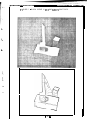
PRIMER
IMAGE INPUT, OUTPUT AND XGP’ing.
After you have an image and its contours; you can save one or the other or both on disk fites;
or print one or the other. The “0” command will output a video image file, in the new hand-eye 200
octal word treader format. The “I” will input a video image from such a hand-eye file; if the file is not
216 by 288, the17 the center of the image will be placed coincident with the center of a 216 by 288
window and the image will be repacked with undefined pixels set to zero. Both the “I” and the “0”
command%. will ask for a filename; if an extension is not explicitly given the default extension “TMP”
WIII b e uce>ed. The “do” command will output the CRE data structure and the “o/,1” command will input
CRE data structure, naturally the default extension is “CRE”.
The “X” command will output a video image to the XGP. The ‘W’ command followed by a list of
octal number-s will output the KEG and VSEG; raw vector contours, to the XGP. The “P” command will
output the currently displayed III buffer, the default extension is “W’. Finally, the “J” c o m m a n d
enhances the contrast of an image for the sake of its appearance on the XGP.
INTERACTIVE (MANUAL) MULTI IMAGE PROCESSING.
Taking or inputing new television images, and contouring them using the “C” command or the “Q”
command will form a film data structure. images can be explicitly compared and linked by typing “M”
match command which links the latest image with the immediately previous image. The “2” command
will zero the data structu% of all images.
AUTOMATIC MULTI IMAGE PROCESSING.
The “A” command is for automatic turn table perception, CRE takes 64 pictures from camera #3
Chile rotattng the turn table, outputs a file and exits (returning control to the 30 geometric editor).
The turn table is manually moved small amounts by the four possible “Y” commands: “Y”, “,Y”, “fly”,
and “(Y”. Numeric absolute and relative posttioning of the turntable is under the “U” command; the
details of which are still being developed.
- 35 -
CRE TELETYPE COMMANDS
VIDEO COMMAI’JOS
T
t.4 P
S
C-J s
/i?S
‘S
Take a q-bit televtsion picture.
Take a 6--bit television picture.
Select camera number, default is camera #I. ”
..
Set TCLIF, default is 0.
Set BCLIP, default is 7.
Shrink node space. Calls node storage compactor.
command characters “T” and ‘5” control live video camera input. The default camera is
The
camera itl on the Cohu camera on the hand eye table. Camera q0 is the Cart Receiver, camera #2 is
the 5ierra hand eye camera, and camera *3 IS one or the other old brown cameras depending on
which coax IS plup,ged up, the brown camera near 11123 is the Font Camera and the brown camera near
the turntable IS the GCOMED Camera.
t:uo
L
INPUT OUTPUT COMMANDS
I
c/I
0
.
C‘
5’ 0
1
X
P
CC
I
i
‘J
Ii
‘i
Input TMP file.
Input CRE file.
Television imaze from disk file.
Contour film from disk file.
Output TMP file. Television image to disk file.
Output CRE file. Contour film to disk file.
Output video image to XGP.
Output III file.
III buffer for calcomp plotter.
Output WC contour edges to XGP.
This command requires a list of octal numbers.
Con1 r-ast enhancement for the sake of XGP appearance.
Type twenty CRLF’s to clear page printer.
Display help summary of CRE commands.
IMAGE CONTOURING COMMANDS
h
I
C Cut at g~‘+n threshold levels.
Q Cut at equally spaced conttours, three cuts: 20, 40, 60.
CfQ
Seven c tits: 10, 20, 30, 40, 50, GO, 70.
E t:nablc ,311 CI;1E processins.
D Disal~i~ ,\I1 r,tcps e x c e p t c o n t o u r i n g .
M
W
Compare and mate match current image wrth previous.
Enter- Arc Width Table alter mode,
,
- 36 -
CRE TELETYPE COMMANDS
NODE FOLLOWING COMMANDS
+
Fetch film node.
Flush node display.
!
cw,,ccw
L’>
u
I
c
v
DADJON
TYPE,,RELLOC
n ENDO,,EXO
2 ALT,,NCNT
3 NGON,,PGON
A NTIME,,PTIME
Fetch Ring links.
Fetch Tree links,
Fetch
Fetch
Fetch
Fetch
nested polygon tree links,
alternate shape or arc link.
nested polygon tree links.
time line links.
1.
These 14 commands allow detailed inspection of the CRE data structure by showing the contents
of a node. Data halfwords of a node are displayed in octal; link halfwords are displayed prefixed with
a letter indicating the type of node being pointed at; a zero link is displayed as “NIL”.
r
The FILM node, which is the root of the whole data structure is fetched and displayed by the
“+I’ command. From the Film, the “>” command can be used to get SON(FILM) which is always the first
image, and I’>” command of an image will get a level and ‘5“ of a level will get a polygon. Vectors and
polygons a r e i n t e n s i f i e d w h e n t h e i r c o n t e n t s a r e b e i n g d i s p l a y e d . The exit command is I’!“, which
leaves the screen less cluttered.
c-
WINDOW SCROLLING COMMANDS
L
‘:
L
L
L
;
i
>
Move
Move
Move
Move
camera
camera
camera
camera
left.
right.
down.
up.
t
d-2
/
\
Zoom out, shrink displayed image.
Zoont in, expand displayed image.
Reset scrolling window to it initial position and size.
Halve !,trength of scrolling delta.
Double strength of scrolling delta.
c)
CL+,
p++
G
Single step displayed image forwards.
Single step displayed image backwards.
Run film display forwards.
Run film display backwards.
The first :,everal commands allow minute examination of the image by magnification and window
posit roning. The command character “w” allows single stepping thru the film of images or oontinous
display of the film forwards or backwards.
- --i---
I
-37-
CART DRIVING COMMANDS
F
Dri\/e forwards
B
Drive bat kwards.
L
Turn wheels hard left.
R
Turn wheels hard right.
t:z/ L
Pan camera left,
+R
Pan camera right.
SPACE Stop the cart.
RETURN Exit cart command mode.
First, and most important is understanding how to stop the cart. The teletype halt command is
SPACE; also any character other than “F”, “R”, “L”, or “R” will stop the cart. Cart commands are
passed first from a teletype to the PDP-10; then to the PDP-6; then over a citizens band, 27.045
megahertz, radio link to the cart control logic. When communication is lacking between entities in the
chain of commat~c~ the lower entity times out and causes the cart to halt. The cart control loaic times
out in a fifth of a second if it does not hear from the POP-6; the PDP-6 times out in less than> minute
if it has not heard from the PDP-10; the PDP-6 stops broadcasting cart commands if it detects the
death of the PDP-IO; the PDP-10 job times out after 5 minutes of not hearing from the ,teletype and
kills the PDP-6 spacewar job.
Second, and of occasional interest is understanding how to make the cart go. The command “F”
wtll make the cart go forwards; and the other commands will cause action as mentioned in the table. If
the cart fails to move; z&its switchs should be check for being in the ON or AUTOMATIC or FAST
position; all its plugs should be plugged in; and its batteries should be checked. Recently cart failure
had been most often caused by the radio transmitter in the Kludge Bay. Check to see that t h e
transmitter is turned on and that the PDP-6 is running. By the end of the year (1973), a n e w c a r t
radio controler will be installed by Hans Moravec, and these commands will be updated.
CART HARDWARE DIAGONOSTIC
v
RETURN
L
L
Enter diagonostic listen loop.
Exit diagonostic listen loop.
NUMERALS: 0,1,2,3,4,5,6,7 send direction relay bits.
CHARACTERS: H,A,B,C,D,E,F,G send action relay bits.
The cart diagonostic listen loop simply takes the low order four bits of a non-carriage return
ASCII character and broadcasts them to the cart. The cart decodes four bit radio command bytes into
six relays; cornrilands 0 thru 7 set the pan, drive, or steering direction relay repective to bits 4, 2 and
1; c~ommancls A thru G set the pan, drive, or steering action relays respective to bits 4, 2, and 1 .
.
- 38 -
II
SAIL INTERFACtNG TO CRE.
/
It should be possible to embed the CRE machine code under a SAIL core image; however 1 do not
intend to do this work. For the present, the CRE interface to SAIL is only realized via a disk file
transfer of the data structure. A CRE file may be read into an integer array in binary mode as
illustrated below.
i
1 I\.
The first \Ivord of a CRE file IS the first word of. the film node which contains the size of the file
in words. The film node has address 0; the next node has address 7; and so on in multiples of seven.
There at-e no empty nodes in a CRE file. The following SAIL program will read in a CRE file named X:
COMMENT EXAMPLE OF SAIL INPUT OF A CRE FILE;
BEGIN “TEST”
INTEGER SIZE;
OPEN( l,“DSK”,8,3,0,0,0,0);
LOOKUP( 1 ,“X.CRE”,O);
SIZE c WORD&J< 1 j;
BEGIN
INTEGER ARRAY NODE[O:SIZE];
ARPYINC 1 ,NODE[ 1 ],SIZE- 1);
PELEASE( 1);
“MAIN PROGRAM.“;
END;
--.
END;
After the NODE array IS loaded, CRE links and data may be accessed by their document names in
a rea:..onablc node-llnk notation using macros like the following:
1
t
DEFII\JE
~EFIPJE
DEFII\JE
DEFlNt
L
CWCQ, = “(NO@E[Q] LSH -18)“;
CC:W(Q) = “(NODE[Q] LAND ‘777777)“;
DAD(Q) = “(NODE[Q+ 13 LSH - 18)“;
SON(Q) = “(NODE[Q+i J LAND ‘777777)“;
So that the first vertex of the first polygon of the first level of the first image of the film can
be obt dined:
1
INTEGER FILM,IMAGE,LEVEL,POLYGON,VERTEX;
M *
L
.
FILM + 0;
LEVEL L- SON(FILM);
POLYGON c- SON(LEVEL);
VERT1.X 6 SON!POLYGON);
rile llser tnay note that SAIL will compile three or rtlore instructions for what is known as a
PDP- 10 ttalfword oper-dtion; also if the user converts the CRE nodes and links into LEAP items a n d
a55w I~!lon~~ then an overhead of from ten to one hundred instructions per “halfword operation” will
t,c,
inc
urrcd.
-
-39-
LISP INTEPfACII‘JG TO CRE.
i
i
i
It shoald he posstble to embed the CRE tnachlr~e code under a LISP core image; however I do not
intccnd to do tllrs w o r k . For the present, the CRE Interface to LISP is only realized via a disk file
transfer- of Itle d a t a C.tructure. A CRE file may be read into LISP binary program space and accessed
u:.inc, the CRE nomenr;clature (1 1 lrnk names and 13 datum names) by means of the S-Expression
5 u I:) I 0 u t i n F! s provided in the file CRE.LSP[CRE,BGB]. The subroutines work in both the old Stanford
LISP 1.6 a<, welt as the newer UCI LISP and Micro Planner, PLNR. The CRE.LSP[CRE,BGB] can be loaded
either by one or the other of the following two LISP statements:
\
(DSKlN(CRE,BGB)(CRE.LSP))
(INC(lNPU1 (CRE,BGB)(CRE.LSP)))
t
A CRE film file is read into LISP binary program space by one of the three possible INCRE
format<,:
(INCRE filename)
(INCRE filename project)
(INCPE filename project programmer)
L
.
,
r-
Filenames should be six characters or less, projects and programmer initials should be three
characters or less, the filename extension CRE is assummed and the usual PPPN defaults occur. If the
input succeeds INCRE returns a value T; if the input fails INCRE returns a value NIL and prints one or
the other of these two rr&ssages:
CRE FILE NOT FOUND.
CRE FILE REQUIRES 00000 MORE WORDS OF BINARY PROGRAM SPACE.
After a cucess fu I INCRE; the film, image, level, polygon, arc and vector nodes are referred to by
integer-s IJ~~III~: the 11 Link Fetch SubroutInes:
L
(CW node)(CCW node)(DAD node)(SON node)(ENDO node)(EXO node)
(ALT node)(NGON node)(PGON node)(NTIME node)(PTlME node)
The film node’s address IS the integer 0, zero.
S o t h a t t h e e x p r e s s i o n (SETQ
V3(CCW(CCWtSON(SON(SON(SON 0))))))) will retrieve the lower right h a n d c o r n e r o f t h e b o r d e r
polygon of the -1 level of the first image of the film. The 13 CRE.LSP datutn fetch subroutines are:
e
(ROW nodc)(COL nodc)(CRETYPE node)(RELOC node)
(CNTRST node)(NCNT node)(ZDEPTH node)(PERM node)(AREA n o d e )
(MXX node)(MYY node)(MZZ node)(PXY node)
- 40 -
This is sample out*put from the Xerox Graphics Printer,
l~~Al~~~coac~~uv3~~~~Nz~~~v
!“a$%&‘O~+,-./O 1234567%9:;<=>?
@ABCDEFGHIJKLMNOPQRSTUVWXYZ[\lT+
“abcdefghijklmnopqrstuvwxyzIlfl1
.
This is sample output from the Xerox Graphics Printer.
1oc/3fw-Ama cmJv3sw~~~Pi~~v
.
'"#$7~'0*~,-./01234567~~:;~~>?
~~~BCD~FGHIJKLMNO~RSTUVWXYZI\l[c
‘abcdefghijklmnoplrst uvwxyz~Ifl1
This is sample output from the Xerox Graphics Printer.
~oL~Al~Ttho$c~nuV3~~-~~~~~v
!“~$E7,&‘0~+,-./O 123456789:;<=>?
a~BCDEFGHIJKLMNOPQRSTUVWX'YZI\ITe
‘abcdefgh.ijkimnopqrstuvwxyzIlfl)
This is sample output from the Xerox Graphics Printer,
.Id~Al~nXooac~nuV~~~-j~#~~~v
!“#$%&‘Ot+,-./o 123456789:;<=>?
aABCDEFGHIJKLMNOPQRSTUVWXYZ[\IT+“abcdefghijklmnopqrstuvwxyzIlfl1
This is sample out,put from the Xerox Graphics Printer.
JIc&~E~~~ac~nuv~@~ -+&2fV
!%$%&‘O*+;,/O 123456%9:;<=>?
eABCDEFGHIJKLMNOPQRSTUVWXYZ[\Ir+‘abcdefghijklmnopqrstuvwxyz1Ifl1
This is sample output from the Xerox Graphics P
rinter,
@ABCDEFGHIJKLMNOPQRSTUVWXYZ[\IT+
‘abcdefghijklmnopqr&uvwxyzCIflI
-
41
-
‘i .-
USING TVFONT - draft.
Introduction.
TVFONT is a
v e r s i o n o f CRE (January 1973)
that
was
spm, i a I i zed t o t h e t a s k o f c o n v e r t i n g t e l e v i s i o n images
into type
f o n t s f o r the X G P ,
X e r o x G r a p h i c s P r i n t e r . T h e o r i g i n a l i d e a was to
denmns t r a t e t h e u t i l i t y o f a p o l y g o n r e p r e s e n t a t i o n f o r scaling,
moo th i ng a n d e d i t i n g t y p o g r a p h i c a l g l y p h s ;
the resulting h a c k
( d e m o n s t r a t i o n p r o g r a m ) w a s e x t e n d e d a n d d e v e l o p e d b y Tovar flock
i n t o t h e p r o g r a m c a l l e d TVFONT. Accordingly, t h e main i d e a o f TVFDNT
i s to convert video rasters
into polygons,
t o e d i t a n d scale t h e
po I ygons, a n d t o c o n v e r t t h e p o l y g o n s b a c k i n t o b i t r a s t e r s .
1
This section IV,
wi I I b e a v a i l a b l e as a T V F O N T user manual
in
a n o t h e r s i x months: i t is p r e s e n t e d h e r e to g i v e t h e would be
u s e r a s t a r t , a n d t h e g e n e r a l r e a d e r a sample o f t h e d e s i g n and
extent of TVFONT.
L
L
i
.
The
figure
on
page
41
is
an
example
of
expanding
and
c o n t r a c t i n g a font w i t h o u t manual t o u c h i n g u p . T h e t o p sample is the
o r i g i n a l (BDR40 f r o m CMU). T h e rmainder h a v e b e e n g e n e r a t e d b y
TVFONT. The expans i on or contract ion ~-l-as done by c o n v e r t i n g f o n t s
from
b i t m a t r i c e s i n t o a polygonal representation,
multiplying by
t h e appropr i ate
c o n s t a n t and
r e c o n v e r t i n g back
into
a
b i t
r e p r e s e n t a t i o n . The fo I I OLD i ng paragraph
i s a n e x a m p l e o f a f o n t made
from t e l e v i s i o n p i c t u r e s :
L
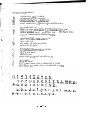
&lK
Bw:
3JU&UXlTOM,
k-kM!jWc?
BLI
B
IXlflFITC,
JliO(,OM
hlal.milIa
IM3hICpC,
II
OYCIIb
rrrGica.
KpOhW
TOI’O,
BO~MOXIIO
B03MO>KIIO fIE!Y aT;1Tb
TOlKe 33MCTWi4 XO$7OLWl UISI~OKO-lleYliTb He
PyCCKOhly R3LIK)‘. CCfiWC RCpIIIOCt 113 ,?IIT’JIiIiiCKI1c’r S’ISUK.
.
- 42 -
UOJl30BaTbC5l
jw6bw
WIJlyCTp3rfHSl.
iTOMOraeT MOeMy nJIoxoMy
T V F O N T P R I M E R - (draft).
i
t
T V F O N T i s on the system, and can be run by typing “R T V F O N T ”
a t a 111 d i s p l a y c o n s o l e .
A t p r e s e n t , III #23 is next to 43
camera
setup for making fonts.
T h e p r o c e s s o f nlak i ng a n e w X G P f o n t or
a l t e r i n g a n o l d o n e w i l l b e e x p l a i n e. . d i n s i x s t e p s :
i ‘4
1.
2.
3.
4.
5.
Raster input:
Contour i ng:
Polygon editing:
Polygon I/O:
Font output:
get a video image or an old font,
make po I ygons.
delete, scale, position and alter,
save and restore polygons.
make n e w f o n t a n d o u t p u t f o n t f i l e .
Complexi t y a r i s e s i n t h a t t h e r e i s m o r e t h a n o n e w a y
to do
each
step, t h e r e a r e d e f a u l t a r g u m e n t s a n d switchs w h i c h
the user
may a l tw, there are ways
to save and restore intermediate resul ts,
t h e r e a r e q u i t e a f e w d i f f e r e n t d i s p l a y modes a n d d i s p l a y
and
The TVFONT command scanner resembles that of TVED and
diagonostics.
a s C R E a n d GEOMED); t h e c o m m a n d s c a n n e r t y p e s a n
( a s 14eI I
E;
when it is
as tcr i sk ‘I*”
i n i t s t o p most l i s t e n l o o p w a i t i n g f o r a
s i ng I e command character .
T h e conmand character may be mod i f i ed by
t h e META a n d C O N T R O L k e y s r-lhi ch 1Ai I I be abbreviated a s “ a ”
“(3” and
II II
f o r C O N T R O L , META, and META-CONTROL respect i ve I y. Many’ conmands
c
in turn require arguments such as numbers or fi le names.
Finally t h e
command
waits
for
an
”x”
e x t e n d e d c o m m a n d name o f sever a I
c h a r a c t e r s . which i s cat I ed an extended c o m m a n d .
c
T h i s f i r s t e x p l a n a t i o n w i l l p r e s e n t a w a y o f making a
f o n t u s i n g t h e feblest c o m m a n d s .
new
Raster Input a n d C o n t o u r i n g :
take television picture.
1,
”T”
“H”
2.
Display histogram of television picture.
3.
” C24 ”
C u t at intensity level 2 4 ,
Get the Font Camera looking at a single letter in a font
b o o k . l.Jse a b l a c k p i e c e o f p a p e r bjith a s q u a r e c u t o u t a s a mask t o
i s o l a t e t h e letter. The “T” command will take a television p i c t u r e .
The “H” command wi I I display a histogranl o f
the television picture,
shou i ng how m a n y p o i n t s o f t h e i m a g e Iderc 0 i n t e n s i t y , ( t o t a l black)
and how many po i tl t s of the i nlage were 77
i n t e h s i t y , {total w h i t e ) . A
p i c t u r e o f a black g l y p h on a whi te background surrounded by a black
mask s h o u l d y i e l d a histogram with two peaks.
Next the “C” c o m m a n d f o I I omd by an octal number fo I I owed b y
a car-r i age return: contours the i m a g e a t t h e g i v e n o c t a l i n t e n s i t y
c u t thresh0 I d.
That is al I the points of the image above
the
threshold are inside of a polygon.
The intensity value of the
I omst val l e y between the two peaks o f t h e h i s t o g r a m i s p r o b a b l y t h e
b e s t c u t v a l u e ( a n d i s p r o b a b l y t h e o c t a l n u m b e r 2 4 or 30).
T h e c u t
cormand, w i I I d i s p l a y t h e p o l y g o n s t h a t a r e made,
- 43 -
Polygoh
Killing.
4.
5.
6.
7.
”c+”
“K”
II
II
II ; II
F e t c h 1 s t p o l y g o n o f 1 s t i m a g e o f t h e f i Im.
Kill a p o l y g o n .
ring around the polygons of an image.
flush node display,
Given an i niage of po I ygons c o r r e s p o n d i n g t o one
letter,
undes i red po l ygons can be del eted by using the “K” c o m m a n d and the
n o d e I i n k d i s p l a y c o m m a n d s . T o s t a r t , t h e “c+”
l*Ii I I i n t e n s i f y t h e
first polygon of the image’s polygon ring;
from t h e r e t h e “,‘I
commands
1di I I
i n t e n s i f y t h e next polygon of t h e r i n g ;
t h e “K”
c o m m a n d wi 1 I d e l e t e t h e p r e s e n t l y i n t e n s i f i e d p o l y g o n and
fetch the
n e x t po I y g o n .
i
L
An
A font corresponds to a f i Inl.
taking a series of iaages,
letter.
After
polygons a font fi le c a n b e m a d e u s i n g :
L
image
corresponds
to
a
and deleting undesired
Making and Outputing a Font File.
k8.
I
L
I
L
I
L
9.
10.
“X”CENTER
”Q”
”c0”
Center al I the images of the f i lm.
Make font bit rasters.
Output font file.
The “X”CENTER command i s an extend mode command and requ i res
b o t h h i t t i n g “X” a n d t y p i n g o u t
the word “ C E N T E R ” fo I I owed by a
carr i age return. T h e ‘IQ” wi I I c a u s e a b i t r a s t e r t o b e made f o r
the
i n t e r i o r p o r t i o n s o f e a c h image o f t h e f i l m ; i f a n
image node does
have an associate ASCII code then the user wi I I b e r e q u e s t e d t o
not
ask for a font f i lenanle and wi I I
sup.p I y one. The “(0” wi I I
output a
font fi le in the Stanford Format.
L
Test i ng a tie\-1 Font F i I e.
11.
. XGP FILE/FONT=NEWFNT. FNT [XGP, E3GB3
The above monitor command wi I I print a F I L E with a new font.
T h e u s e r must s p e c i f y h i s P P P N b e c a u s e t h e d e f a u l t i s CXGP,SYSL
-- 44 -
TVFUNT COMMANT3 SUMMARY
A
B
C&J
FR
CB
e
ASSIGN ASCII CODE TO IMAGE.
EXPAND/CONTRACT BY CONSTANT
,EXPAND/CONJRACT I N Y OIRECTTON
EXPAND/CONTRACT IN X DIRECTION
SLANT CHARACTER (l/2 SLANTS TO 45 DEGREE ANGLE)
C
cc
cl
F
G
MAKE THRESHOLD CUT.
MAKE POLYGON IMAGE OUT OF I311 REPRESITNTATION OF FONT
ENARLE/DISARLE DELETION OF f)ANY POLYGONS (OEFAULT IS'OFF).
LOCATE NEAREST POINT, tF USE LIGHT PEN
LEVEL OF CORRESPONDING CHARACTER COOE
Ii
I
cd
K
I-
HISTOGRAM, %H"
"OH" BI-MODAL C U T ,
INPUT TV PICTURE'FROM DISK.
INPUT CRE FILE
KILL IMAGE, POLYGON OR VERTEX
SHOW LAST BIT IMAGE
SHfllJ CH-ARACTER FROM FONT IN FNTSEG
MOVE POLYGON TO NEXT IMAGE.
MOVE TO NEW IMAGE
MIDPOINT LINE
MUNG ONTO GRIU POINT (AS SEEN IN cY)
NEXT IMAGE
I-'RL V I OUS IMAGE
REKAT NEXT IMAGE UNTIL A CHARACTER IS TYPED
REF'FAT PREYIUUS IMAGE UNTIL A CHARACTER IS TYPE0
,
- 45 -
t *
1
TVFQNT COMMAND SUMMARY
0
CiO
CO
L
1
i (-
P
u
au
i
OUTPUT CAREYE FILE.
OUTPUT CRE FILE
OUTPUT FONT FILE
PLOT OUTPUT FILE.
R
UK'
MAKE FONT
MAKE 3.12 SIZE FONT
PISPLAY BIT MATRIX FOR THIS CHARACTER
ROTATE IMAGE, LEVEL OR POLYGON (ANGLE'IN RADIANS)
S
03
L.
PS
cs
SMOOTH
SMOOTH AND KILL VIDEO INTENSITY CONTOUR
L
T
CfT
REPEAT 'S' FOR EACH IMAGE
REPEAT ‘as’ FOR EACH IMAGE
TAKE A TV PICTURE
TAKE A TV PICTURE, SETTING CLIP LEVELS AUTOMATICALLY
L
CREATE VERTEX AT CENTER
CREATE I'dEW VERTEX AT CURRENT VERTEX
CREATE NEld VERTEX IN NEW IMAGE
w
aW
. PM
CR
X
.
I
Y
PY
UY
tY
z
aZ
PZ
CENTER IN THE WINDOW.
CENTER Y-POSITION ONLY.
CENTER X-POSITION ONLY.
MOVE POINT SPECIFIED BY LIGHT PEN TO CENTER.
XTEND MODE COMMANDS
DISPLAY SMOOTHED FORM
DISPLAY VIDEO INTENSITY CONTOUR
CIISPLAY BOTH OF ABOVE
DISPLAY VIDEO INTENSITY CONTOUR MUNGEO ONTO PIXELS
NO-UP
RESET LOGICAL CAMERA POSITION
RESET DISPLAY
- .
- - 46 -
,
TVFONT COMMAND SUMMARY
+
cr+
P+
t+
Fetch f i 1111 n o d e .
F e t c h f i r s t image n o d e f r o m f i Ihi.
F e t c h f i r s t levd f r o m f i h.
F e t c h f i r s t poIyg~.ri from f i hi.
IF A NOOE IS CURRENTLY BEING DISPLAYED, THESE COMMANDS AFFECT THAT NODE
OTHERWISE THEY AFFECT THE CAMERA (VIEWERS) POSITION. <CONTROL> MULTIP&
BY 2, <META> MULTJPLIES BY 4.
MOVE LEFT (~1 BY DELTA
MOVE RIGHT (4) BY DELTA
MOVE UP BY DELTA
MOVE OOWN BY DELTA
OI’UOE DELTA BY 2
MULTIPLY DELTA BY 2
THESE COMMANDS AFFECT THE CAMERA (VIEi,JERS) POSITION.
INCREASE MAGNIFICATION BY DELTA
DECREASE MAGNIFICATION BY OELTA
*
THESE COMMANDS CHANGE NODE BEING DISPLAYED.
.
FETCH COUNTER CLOCKWISE NODE IN RING.
FETCH CL.QCKW?SE NOCJE IN RING.
.
<
FETCH FATHER OF NODE
>
FETCH SON OF NOCtE
-<
FETCH ARC COF t'OLYGON OR VERTEX3
3
FETCH F'OLYGON [OF VERTEX1
A
EUUIVALENT T O * <,>'
V
EQUIVALENT TO '<.>*
!
FLUSH NODE UISPLAY
THESE COMMANDS AFFECT THE PUSHClOWN LIST
PUSH NOOE BEING DISPLAYED ONTO STACK
n
POP NODE OFF STACK AND DISPLAY IT
4-b
SWAP NODE BEING DISPLAYED WITH TOP OF STACK
U
s
- 47 -
TVFONT ’ S EXTENDED COMMANIlS.
ARCWTD
Set smoothing constant.
Th i :s i s t h e max i mum d i s t a n c e a vet- tex
may f r o m a a r c b e f o r e i t i ’ s s p l i t i n t o t u o a r c s .
See d e s c r i p t i o n
of shloothi ng al gor i thrill on Page X X .
RAWK T 11.
T o g g l e f l a g w h i c h c a u s e s b a b y p o l y g o n s ( t h o s e c o n s i s t i n g o f only
one p i x e l ) t o b e k i l l e d )
CAMERA
Select a different camera number.
L
CENTER
C e n t e r a l I i m a g e s . I t i 5 equ i va 1 ent to the command ‘w’ app I i ed
to each image md uses the same contra I bi ts.
I
i
I-I
--.
I n v o k e D O T i f p r e s e n t , r e t u r n w i t h aP,.
DOT
fl1 SPI. AY
t
Enable d i s p l a y .
-L-l I SPLAY
D i3ab I e d i sp I ay.
TVFONT spends a s i g n i f icant a m o u n t o f t i me
p u t t i n g u p the d i s p l a y .
L
EXIT
Ex i t to mot7 i ter.
GRJPJ
a
Er1;jbto d i s p l a y o f g r i d . G r i d i s sohie m u l t i p l e o f p i x e l s i z e ,
depr!nclen t on camera f oca I I ength.
I t is useful of lining up
(;hwacfers.
-GR IO
Cl i sab I e d i sp I ay of gr i d,
[3isplay h e l p f i l e .
HOLE
Change a polygon into a hole.
KII-ARC
Ki I I arcs vectors.
T h i s al l o w s s e v e r a l d e g r e e s o f moothi ng to
b e t r i e d i n c o n j u n c t i o n Glith t h e ARClJID conlhland,
- 48 -
Ii
i
TVFONT’ S EXTENDED COMMANDS,
KILVTC
Ki I I v i d e o i n t e n s i t y c o n t o u r s - a n d r e p l a c e s t h e m w i t h a r c s .
MUNG
Force al 1 vertices of current polygon or level onto pixel b o u n d a r i e s .
T h i s h a s a p e r m a n e n t e f f e c t a s o p p o s e d t o ‘0’ conmand w h i c h o n l y
d i s p l a y s them t h a t ~-lay.
ORTHMUNG
O R T H M U N G f o r c e s v e r t i c e s w h i c h appear to be form right a n g l e s o n t o
pi xe I boundar i es.
T h i s is attempt to counter the rounding effect
of dek i nk i ng on sharp corners as are generated by r e a d i n g a f o n t .
POLYGON
C h a n g e a hole into a polygon
POPJ
Leave TTY loop.
Used for debugg i ng.
REAUFONT
C o n v e r t f o n t w h i c h h a s b e e n read i n t o t h e f o n t s e g m e n t i n t o p o l y g o n a l
r e p r e s e n t a t i o n , d i s p l a y i n g exh character as read.
L
SCALE
I
Scale al I images b y c o n s t a n t .
t o e a c h image,
I
Equivalent to the command ‘B’ a p p l i e d
SLANT
S l a n t a l I images b y c o n s t a n t .
complete description.
PI ease see conmatid ’ ~8’ for
a more
SilRi
Sort i nlages on f i In1 according to ASCI I c o d e .
T h i s i s for conv i ene’nce
in looking a fonts sequentially.
The 'G' command. i s recommended for
finding specific c h a r a c t e r s .
XEROX
OUTPUT TV IMAGE TO XGP
XSCALE
%-de al I in1age.s b y c o n s t a n t i n t h e X d i r e c t i o n . E q u i v a l e n t to the
cohlnlnnd ’ CUB’ appl ied to each image.
YSCAL E
S c a l e a l I images b y c o n s t a n t i n t h e Y d i r e c t i o n . E q u i v a l e n t t o the
c o m m a n d ‘06’ appl ied to each i m a g e .
- 49 -
-.
TVFONT NODE FORMATS - JAN 1973.
---__
I
I
VERTEX/ARC NODE,
POLYGON/REG I ON NODE,
I
0
1
L‘7
VERTEX-RING
ROW, ,COL
TYPE,,RELOC
0
1
LCI
POLYGON-RING.
DAD, , SON
TYPE t , RELOC
5
--I
ARC,
t
, , PGON
R? SEG, .LT S E G
4
5
6
ARC: : NCNT
- , , PGON
I
I
I
I
I
I
I
I - I
I
I
I
I
2
3
0
1
2
-o-
:
-5
3
4
5
6
-,*-
I
EMPTY NODE,
I
I
(
I
0
I
I
I
I
I
I
CORESIZE
, ,SON
iTYPE, ,RELOC
.3
- , ,AVAIL
4
BLOCK C’OUNT
0
- ,,AVAIL
5
-,,-
2
3
4
TiPi:, RELOC
-;;I
6
-yv-
6
_----I___
5
I
I
f JLM NODE.
I
I
-+v-
1
1
I
- ,,NCNT
-9*-
AI --zL.-,--
I
I
-,*-
4
LEVEL-RING
SON
TiPi:, RELDC
I
I
I
J MAGE-RI NG
- ( ( SON
TYPE, ,RELOC
I
I
I
l
I
I
I
I
I
I
-ve-
0
1
I
I
-
I
I
I
I
-
LEVEL NODE,
I
e
6
3
I MACE NODE.
I
I
I
I
3
4
I
I
I
I
-9v-
-t(-
SEGMENT NODE.
0
SEGMENT RING
1
2
TiPi:,i00003
3
LDEL,,RDEL
4
LCOL, , RCOL
5
I-ROW, , RROW
6
LT. ,RT
I
I
I
I
I
I
I
I
I
I
I
I
I
I
I
I
I
I
I
I
I
I -.--- -.___-
i
- 50 -
SUMMAIIY OF LAMlNA INERriA TENSOR EXI'RESSIONS.
t
RECTANGLE'S
I
LAMlNA INERTIA TENSOR ABOUT ITS CENTER OF MASS.
MXX
MYY
MZZ
FXY
+
++
6
(E3 HEIGHT IN ROWS)
(A WIDTH IN COLUMN&.
B*R*AREA/12;
AmA*AREA/12;
MXX + MIYY;
0;
ORIENTED RIGHT TRIANGLE'S LAMINA INERTIA TENSOR ABOUT ITS CENTER OF MASS.
MXX
MYY
MZZ
PXY
c
+
ic
BdkAREA/L&
A#AxAREA/I.&;
MXX + MYY;
-AaB*AREA/36;
(8 HEIGHT IN ROkfS),
(A WIDTH IN COLUMNS).
SUMMATION OF LAMINA INERTIA TENSORS.
L
AREA
XCM
KM
MXX
I
,!
b-
L
Y
L
L
1
+
+
+
--' c-
MYY
c
PXY
c
( A R E A 1 + AREA2);
(AREA1 * XCMl + A R E A 2
( A R E A 1 sk KM.1 t A R E A 2
MXXl t YfMl:+YCMl*AREAi
MXX2 t YCM2*YCM2*AREA2
MYYI t XCMl*XCMl*AREAl
MYY2 t XCM2*XCM2*AREA2
PXYl - XCMlaYCMl*AREAl
PXY2 - XCM2*YCM2*AREAZ
>i( XCM2) / AREA:
* YCM2) / AREA:
t
- YCMe'CM*AREA;
+
t
t
XCM*XCM*AREA;
XCMsYCMwAREA;
ANGLE OF PRINCIPLE AXIS
R-l I
PXY
c
c
B.SxATAN(IMYY-MXX)/(2*PXY))
0,SdMYY - MXXhTAN(2*PHI)
TRANSLATION OF LAMINA INERTIA TENSOR AWAY FROM CENTER OF MASS.
MXX'
MYY'
PXY'
6
+
(-
MXX t AREAxDY*DY;
M Y Y t AREA*DX*DX;
PXY - AREA*DX*DY;
ROTATION OF LAMINA INERTIA TENSOR ABOUT CENTER OF MASS.
c
s
MXX'
c
c
+-
MYY'
L-
PXY'
6,
CRS~NEwiI):
SINEWHI);
CXCN~IXX
+
SkhMYY - Z*C*S*PXY;
C*CsMYY + %S>r;MXX
+ 2*C*S*PXY;
KXC - S*ShPXY t C*S*(MYY - MXX);
s
- 51 -
REFERF:NCES.
i -I
Ic
t
1-
1
[ll GOLDSTEIN, H. 1950.
Classical Mechanics,
Addison-Wesley.
Reading, Massachusetts.
..
C21 K N U T H , D.E. 1 9 6 8 .
The Art of Computer Programing.
Vo I unle 1, Fundamenta I A I gor i thms,
C h a p t e r 2, Informat i o n S t r u c t u r e s .
Addison-Wesley.
Reading, Massachusetts,
C31 KRAKAUER, L . J . 1 9 7 1 .
Computer A n a l y s i s o f V i s u a l P r o p e r t i e s o f Curved
Project MAC, Technical Report TR-82,
Massachusetts I n s t i t u t e o f T e c h n o l o g y .
Cambr i dge, Massachusetts 02139.
Objects.
[41 ZAHN. C. T . e-.1966.
Tr-JO flimensional Pattern Description and Recognition
via curvature points.
SLAC Report 70.
Stanford Linear- Acceleration Center.
Stmfoi-d U n i v e r s i t y .
S t a n f o r d , Cai I f o r n i a .
.
- 52 -