1
I
iiiilYORK”
SUNLINE SERIES
SINGLE PACKAGE AIR CONDITIONERS
INSTALLATION INSTRUCTION
Supersedes:
530.25-NIY
(488)
Tab DSC
530.25-NIY
(1189)
035-08598
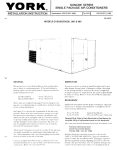
MODELS DISC/D2SC300, 360 & 480
-
GENERAL
INSPECTION
TIIIS [nstruct i<m coters the installation, start-up and operat[on ~Jfthese olr condlt[oning units. If the unit includes a
heating opt Ion, use this lnstructl~m in cmlunctmn
wltli the
proper hc~ting inslruct]on.
As soon as a unit IS [ece[ved. II should he inspected for possible da mge during t IJnslt [ f darndge is ewcfent. the extent
of (he damage SINJUId be noted t~rl the carrier’s f’relght bill.
A sepal ate reques: t(~l inspect](m by the earner’s agent should
be made in writing Reter :0 FOI m 50 15-NM for addltiunal
m foI mat ion.
Gas t Ieut Opt ion
F.lectrlc iieat Optmn
FOI m 5?I0.25-N 1.1
Form 530.25-N 1.9
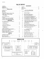
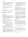
These units are completely packtiged, factory clurged, cooling only or ccruling/ heat mg dir cond it loners. primtir[ly designed f’~~rrw)flop installation.
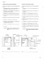
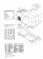
See Figure I tor the ]nterrurl arrangement of the unit cx)nlponents. These un]ts have sem]-hermet]c cornpressu]s w]th
blocked suction unloacilng for’ efficient fIIll and part load
operal mn 8nd can be equ tpped wrt h on ecorronliier opt ton
t<] provide coohng w]th outdoor alr when the temperatures
and the humidity of the outdoor aII permlt. The umt can
also be equipped with ex h~ust alr f~rls 1’01use m conjuncti(m with the econornver option.
All elect rical controls are located on one side of’ [he un]t find
ure re~d ily accessible for maintenance, ~d]ust ment and serwce. All wiring ( power ond cent rt)l ) Jnd piping can be rmde
thru the bottom t~r the s[de of’ the unit.
L
Units aIe tv:lil~ble with bottom duct connections fol lo<~f
muunted Installations or my be field converted for end duct
connectmns. Refer to Form 5?I0.25-N 1.5.
REFERENCE
Acfdltiomrl iniormt
]m on the design. ]nstalkrtm.
operation
and serwce of’ retrlgerot Ion equ] pnwn~ IS,IVJikible lrr the ref’et ence mate I Ill hs[ed below
Gene r:il Installatmn
~le.,t~l [ & post.start Check List
Form 55.70-N I
F’orm 55.70-N2
Renewal Parts: Refer to Parts Microfiche or Parts Manual for
complete listing of replacement parts on this equipment.
All terms lrete]enced m !IIIS mstl uctlorr may be ordeled ftom
Publicatmns D@ribution center
Central Environmental Systems
P.O. Box 1592,
York, PA 17405
Instal]el should pa> paltlculut
Jtten! l~m to tl~e WOIds
Note> ;ire [rrtended to
clar Ify or ma Le [he instdlkrt Ii)n e~sler. (’IU [ I<)IIS,Ire :Iven t o
prevent equipment ckrmge. WaInnIgs
J;e gIvcn to ~lelt the
—
instal[e r t h~t pel w)rml lnl~lr}f .Ind ~lr equlpmen[ dd nmge Ind}
Iesull If [he ]nst,111:1
[ ItlIl pr(lcedu] r 1~not bfind led prt)pel 1}.
,VUTE, CAL’TIO1’,irrd 1$’,lR \l.\(;.
..—
530 25N 1
TABLE
OFCONTENTS
GENERAL
INSPECTlON
RE.FF.RENC1.
NOMLNCLATUK1
:
:
I
1
1
2
:
:
INSTALLATION
LIMITATlONS
RIGGING
:. . . .
MOUNTING
CLEAR/lNCtS.
.“:
.
CONDENSATE. DRAIN CONNFCTlON
PC)WER AND CONTR() L WI KING
Powcl wit Ing
Cent Iol Wiring
3
3
3
3
““”
“.
““
:
OPERATION
LLECTRO-M E.CHANICAL CONTROLS
Lxxrnonluer Sy\(cnl
..
.
lic~tlng Sy5tcnl
cLrulmg system
Lxltaust Air SystcIn
SOLID STATF. CONTROLS’
Lccrnulnucr Systcru
Hed[]ng Syslf2iII
Cooling Systein
l..xbaust Au System
SUPPLY AIR BLOWER ADJUSTMENT’
MASTER PRINTLD CIRCUIT BOARD AND
PL(I(;-IN RELAY ASSENIBLY
SERVICE ANA LYZ1.R
FIXIID OUTSID1: AIR AIIJU”:’IMENT
:
EXt{AUST AIR Pt. RFORMAN(’L
START-UP
CRANKCASE 1{1.ATLRS
SAFETY AND Sl:Rk’l(-l; FEATURES
:
PRL-START (’HECK
INITIAL START-L}’
POSTSTART CI+E(’K L 1ST
:
~q
—y——
I
PRODUCT
j
4
5
6
7
8
9
12
12
13
13
13
.
10
11
11A
IL
13
14
13
14
15
16
17
lx
],)
14
14
15
15
I5
I6
16
TABLE
I
7
18
1q
j
4
5
6
7
8
9
10
11
: 1‘~
[,)
23
: .23
24
24
24
I
I
I
‘i
I
SC -
360 = 30 Ton
480 = 40 Ton
–’
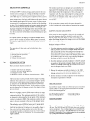
IDENTIFIER
Sun Ilne
r
INSTALLED
HEAT
.——
E – Ele;trlc G – Gas (Mult[-Fuel)
A – Not Applicable
2
r2-~L—.
:
24
24
~
“-
~
F]
e,;,
1
NOMINAL
‘
4
4
I ()
[~
1.?
] (~
17
I ()
j 1
21
22
~
f
1
FACTORY
:
LIST OF TABLES
Applwrtmn
Ihta
Ct)mponcnt Wc@ts
l:lcctr]cal Dald
.
I-I1[cI Rcqu]rclncnts
I:nthalpy (’ontrol (Set Point ‘;~’
Ambient ThcI mostat Scttlng
Supply A)r Systcm Adjustnlcnt
Scrvlcc Analy/cr Functlun Chtirt
...
Blower Motor And L)I wc L)iitir
RcsI\tancc\ - Unit Opttonj and Acccsorlc\
Supply Alr Blower Pcrlormancc
I*]
PRODUCT
: :
Unit Less P~nels .,
.
~
TypIcdl Unl[ Rlggtng
3
C’cn[cr of Grav]ty
3
Rccommcnded Dra]n P]p]ng
~
Bottom Power Wlrlng Enlrance
SIdc Power Wlr]ng Entrance
5
Control Wiring E;trance(DSC300,360).
f]
Control Wiring Entrance (DSC480)
~
Control Wlr]ng Corm’s. Without Status Panel
Control Wlrlng Corm’s. With Sta(us Panel
~
Cent rol Wiring Ccrnn’s., Solid State Control
Wlrlng With Status PaIIcl
.
.. .
~
Control Wiring Corm’s. Solid State Control
Wirinq Without Status Panel . . . . . . . . . . . . .
9
Unit Dimensmns
...
]I
Duct Connectmns . . . . . . . . . . . . .
[~
12
Sound Absorption Chamber
Typical Motor Mounting Assembly .,
]7
Hole Lourtlons Eor Supply A]r (’FM (’hwk
18
Prcwrrc Drop Across Ivapurator L’OI!
]~
l’I\cd Outdoor A]r Adju>tnwnt .,
20
[“.kh;Iu\t
Alr I)er(ornlancc
20
NOMENCLATURE
[3:67i7
[+ [4”0’TJ
.——L-– —
—— ~-,
CATEGORY
,.
IGu RE
1
-1
4
::
24
24
24
.,
LIST OF ILLUSTRATIONS
}
‘$
(~
DUCT (’ONNLCTlONS
.,
.
..........
FILTLKS
..
}itifi)”OPTiON’ ‘. : : : : : :
ECONOMIZER iAl~
FIXED OLITSIDE AIR RAIN HOOD. .
..
.
FXlfAUST AIR RAIN tIOOD OPTION” .,
riiJ IIJ
MAINTENANCE
1:1LTERS
(’OILS
DRAIN PAN
LUBRICAI ION
“.
:
BLLTS
.
HEATING
Gas (Multl-Fuel)
400 Mbh
560 Mbh
800 Mbh
CAPACITY
—
Electrlc
040 =
060
080
100
120
40 KW
= 60 KW
= 80 KW
‘ 100 Kw
= 120 KW
7..
.
530.25-N1
BLOWER
SECTION
EVAPORATOR
FILTER
COIL
ACCESS
CON DENSER
COIL
-
CONTROL
PAN EL
-
COMPRESSOR
COMPAR TM E~
7
COMPARTMENT
FIIG.
1 –UNIT
AIR
COMPAR TMENT
LESS PANELS (DSC 480 SHOWN)
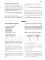
INSTALLATION
LIMITATIONS
CLEARANCES
These units must be inst~lled in accordance with all national
and local safety codes. [f- no local codes apply, insttillatmn
must conform with the appI oprlate national codes. See Table
I for applicatmn data, Units are designed to meet National
Safety Code Standards. If components must be added to a
unit to meet Iocat codes. they are to be installed at the dealer’s and/or the customer’s ex pen se.
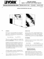
These units must be installed with the mmlmum
listed below.
Front
(Control Box Side)
Left side
[Condenser coil)
Rear
RIGGING
Right side
Sunllne umts ‘ire equipped with lift Lng lugs on the unit base.
Units sh(’uld be lifted by pkrclng rigging hooks thru the logs
provlcled. Spreader bars should be used. See Fig. 2.
clearances
36” for Service Access
to Controls
36” for Proper Condenser Alr Flow
36”
90”
36”
36”
From Rain Hoods
Units with Gas Heat Option
Units with Electric Heat Option
Cooling Only Units
Below unit I
o“
Above unitz
120” for Condenser Air Discharge
1(JoIts with a gas or an electrlc heat}ng option can be [nstalled on a
combust Ible floor.
2Un!ts with gas heat must be Installed outdoors; the products of
combustion must not be allowed to accumulate wlthl n a confined
space and recirculate.
These unIts can be Installed under an outside overhang prowdl ng
the overhang (1 ) ISat least 10 feet above the top of the unit and
(2) extends no more than 3 feet beyond the end of the unn.
A 2“ clearance within 3 feet of the onit must be mamtalned
between any combustible material and the supply air duct
work.
FIG. 2 –
TYPICAL
UNIT
RIGGING
No objects should be left near the combustion air inlet to
obstruct the openings. [f the unit is slab mounted, shrubs
and other growth should be elimmated.
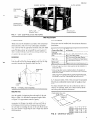
MOUNTING
CO NO ENSER COIL END
The structure on which the unit or roof curb is mounted
must be cxpable of supporting the total weight of the unit
Refer to Table 2 for individual component weights. Refer
to Figure 3 for apprwxima[e centers of gravity.
L
A roof mounting curb accessory ISavailable to simplify the
installation of a Sunline unit, Refer to Form 5 30.25-N 1.6
for Installation instructions for assembling and mounting
the curb and for installing the unit on the curb. Roof mountmg curbs capable of sopporting the unit
weight may also be
field fabricated.
H
FIG. 3 – CENTERS OF GRAVITY
CES
3
530 25-NI
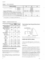
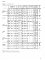
TABLE 1 –APPLICATION
DATA
MODEL DISC/D2SC
Voltage Varlatlon,
Min/Max 1
300
360
200 volts
187/21 8
230 Volts
460 Volts
216/252
432/504
575 volts
8,000/1 2,000
SUPPIY Alr CFM, Mln/Max
‘)
57/72
0/1 15
Dry Bulb Temp. (0 F) of Air on Condenser Coil, Min/Max2
Gas Fired Heater
Minimum Dry Bulb Temp. (“F) of Air On:
Dry Bulb Temp. (0 F) of Air Off: -
—
540/630
9,600/14,400
Wet Bulb Temp. (0 F) of Air on Evaporator Coil, Min/Max
Maximum
480
— —
12,800/1 9,200
‘-
-
20
Gas Fired Heater
160
145
Electrlc Heater
180
180
155
180
T
1Utl IIzat Ion Range “A” m accordance with AR I Standard 110
2 Low Ambient accessory ( Form 530 25 N1 7 ) may be requ !red for 0° F outdoor ambient
TABLE 2 – COMPONENT WEIGHTS (LBS.)
COMPONENT
Outdoor Air OptIon
Fixed Outdoor Air
MODEL
DSC300
DSC360
DSC480
85
247
75
75
Economizer Option
220
220
Supply Air Motor &
Drive 7-1/2 HP
10 HP
15 HP
130
i45
—
—
.
—
—
215
60
60
65
200
300
—
200
300
—
–
3oii
400
E040
110
110
110
E060
115
115
115
120
125
—
120
125
130
120
125
160
160
130
250
300
105
350
105
400
130
G400
<560
G800
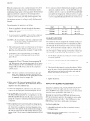
UNIT CONDENSATE
DRAIN CONNECTION
—
—
145
185
—
20 HP
Heating OptIon
Cooling Only
Natural Gas Heat
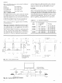
The trap must be at least 2“ deep to mirlnttiin ~ water setil
under all operating condltlf)ns, especially when the bk)wels
ate start ing up,
—
185
\
FIG. 4 – RECOMMENDED
DRAIN
PIPING
Electrlc Heat
E080
E1OO
El 20
Exhaust Fan
POWER AND CONTROL WIRING
Install elect rlc<il wlrtng I n ticcot d.rnce WItb (he Iate\t Na[ I(~Iv
u] Llectrica] (’ode (N} PA Stond~rd N(). 70) and I or locul
regu Itit Ions. Tbe um t shoulci be grounded in Jcci)rdance wlt h
these codes.
Accessories
Roof Mounting Curb
End Outlet Kit
CONDENSATE DRAIN CONNECTION
The condens.rle drain, Ioca[ed on [he rtgh t end of the unit,
shouid be cunnectecl ICI~n open d I tiIn or allowed to d Ischarge directly onto tbe ground or mot. A trap MUST he
[nstdled, See FIgu re 4.
The .3” dlmenslon must equo] 01 e<ceed the negative s[at IC
pressu)e developed by the supply ir)r blowers, If It dt>esn’t,
the condensate will nt)l drfiln properly tind will over! low the
dIa In pan.
4
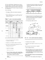
POWER
WIRING
The f’ield power wlrlng can be brought into [he control be)\
through the 4- I /2” di~meter sleeve in the base of the unit
( Fugure 5 ) or through the 3“ threaded corrdutt connector in
the s[de uf tbe corrt rol box ( F!gure (I). The unit I\ eq ulppecl
wlth a corraluIt ter nllna{ lon pkrte above t he 4- I / 2“ dla meter
sleeve. Tbe plate hirs 1-23/32”, 2-l /2”, an(l 3-5/ 8“ dla metet
corrcentrlc knoch~)uts i or units wlt h d )scon rwct swlt cb, t be
power lugs can be rotated 90 degrees clockwlse to fircllit~te
entrance ()[ t be power wiring f’rum the side ut the box 1 (I
do tbls remove t[)c 1/4” bolt bc]]dmg the power lug Next
remove the slot ted spring pm WIIIC}I keeps the Iug I I ()111rotating. Turn the power tug 9(I degrees clockwlse tind I epkrce
both the dotted $pI ing pln and the I/4 ‘ bolt.
CES
—
530.25-N1
-
A non-fused disconnect switch is available as a factory-mounted option on all units. When this option is not included, a
field-supplied disconnect switch should be installed in the
power supply wiring at a location that will meet the requirements of the National Electric Code and/or local regulations.
NOTE. Fused discormect switches are not required because
the power wirirrgmust be fused at [he source.
2. Units that are mounted on structural steel above the
finished roof unless the steel is blocking the 4-1/2 inch
diameter sleeve in the base of the unit. This applies to
units with or without a factory installed disconnect
switch.
CAUTION: The 4-1/2 inch sleeve must be sea[edafter
the pwer wiring has been routed to prevent
possible condensation problems in the unit
control box.
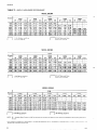
Either inverse time circuit breaker or dual element time delay fuses may be used for overcurrent protection on these
units. They must be sized according to Table 3.
Side entry is recommended
Bottom entry is recommended
1. Curb mounted units without a factory installed disconnect switch because the power wiring must be brought
outside the unit to a field supplied disconnect switch.
for:
1. Curb mounted units with a factory installed disconnect
switch unless the power wiring is already above the finished roof.
2. Slab mounted units with or without
disconnect switch.
CONDUIT
CONNECTOR
(3” Threaded)
CONDUIT
CONNECTOR
(3” Threaded)\
for:
L
1
installed
a factory
yH%qjTJij#c-dj
u //
SPRING PINS (SLOTTED)
u —
/
*
CONDUIT TERM I NATION
PLATE (3-5/8” K.O )
UNITS
WITHOUT
FIG. 5 – BOTTOM POWER
3-518” K
0.
4-1 /2” DIA
/
WIRING
/
?’‘
CONDUIT
(8Y FIELD)
)
,
. i.
1
f
STRAIGHT CONNECTOR
(8Y FIELD)
MODELS
WITH
DISCONNECT
CONDUIT
CONNECTOR
- (3” Threaded)
(BY YORK)
,1
I
4:1 /2” DIA. SLEEVE
ENTRANCE
/
I
UNITS
DSC300,
—.
\
CONDUIT TERMINATION
PLATE (3-5/8” K 0.)
DISCONNECT
\
/
SLEEVE
II
\
360
CONDUIT
TERMINATION
PLATE
(3-5/8” K .0 )
CONDUIT
- CONNECTOR
(3” Threaded)
(BY YORK)
+.
—1
. .
t
3-518’”K O.
.1.
–-L
OUTL:T BOX
(Die Cast)
(BY FIELD)
MODEL
—
\
=@=
-
L J– –
7
FLEXIBLE CONDUIT
(Liquid Tight)
(8Y FIELD)
DSC480
FIG. 6 – SIDE POWER WIRING ENTRANCE
CES
5
530.25-N1
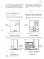
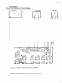
CONTROL WIRING (MODEL DSC480)
(MODELS DSC300, 360)
CONTROL
WI RING
For bottom
routed:
entry ( Figure 7), the control wiring should be
1. Up through the tlexlble conduit and the middle deck to
the proximity
of the hole into the control box.
For bottom
routed:
entry (Figure 8), the control wlrmg should be
1. Up through the 2-1/4 inch O.D. tubing behind the control box.
2. Through the 1-3/8 snap bushing in the condenser evaporator partitton and control box.
2. Through the positioned
control box.
3. Through the 2 ty-wraps positioned
3. Through the 1-3/8 snap bushing m the control box.
in the control box
4. Connect the wires to the printed circuit board per Fig.
9, 10 or I 1.
4. Through
ty-wrap on the outside of the
the 2 ty-wraps posltmned m the control box.
5. Connect the wiring to the printed clrcult board per Fig,
9, IO or 11
For side entry on slab mounted units, the control wiring
should be routed:
For side entry on slab mounted
should be routed
1, Through the 1-1/8 mch K,O. in the corner post.
2. Through the 1-3/8 snap bushing ur the condenser evaporator partition and control box.
units, the control
1. Through the 1-1/8 inch K.O. in the mtermedlate
wiring
post.
2. Through the 1-3/8 snap bushing m the currt ml box,
3. Through the 2 ty-wraps positioned
In the control box.
3. Through
4. Connect the wires to the printed c~rcuit board per Fig.
9, [0 or 11
CAUTION: Wiringpenetration through [he side cntrj
must be sealed ro pre~ent tile entrance of
water.
1-1 /8” K O
R SIDE ENTRANCE
1.3/8” SNAP BUSHING
/ (BY YORK)
~’?
Ik
~n the control box
4. Connect the wiring to the printed clrcult board per Fig,
9, 10 or 11
CAUTION Wiringpenetration through the side entr.}’
must be sealed to preterst the entrance of’
water.
—
the 2 ty-wraps positioned
EXISTING
TY.WRAPS
1-3/8” SNAP BUSHING
(BY YORK)
II’\
.~
‘+
SIDE ENTRY
\
I
-(
-
21 /4” O D
TUBING
(BY YORK)
F>
(
Ii
SIDE ENTRY
1
3TTOM ENTRY
I ‘BOTTOM
L_..–
ENTRY
t
t;
L
---
1
t
W
I!l!-.J
1-1
/8” K O
FOR SIDE ENTRANCE
FLEXIBLE
CONDUCT
(BY YORK)
FIG. 7 – CONTROL WIRING ENTRANCE
(DSC300, 360)
FIG. 8 – CONTROL WIRING ENTRANCE (DSC480)
CES
C
C
ROOM T
O
2
W
S
2
2
W
S
2
O
N
S
J
T
N
S
2
2
1“19 Y1
*
Y2
) )
●
I
I
I[
I
‘
J
S
‘) )’)
I II
I
54
‘) “d
I H
II
1s311
P
C
B
/
/
0
109 110 111 WI
G 114 115
—
—
—
—
—
—
—
12011211122
—
...=
%
●
12TR0
@
S2
*
:0
I Hnrlll
●
●
*
*
o
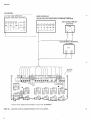
“ For a cool lng only
“ “Switch
5R ~
unnt, omit
mav be replaced
FIG. 9 –
w!th
I
H
e
@
:
the wires from
the contacts
WI
and W2 to the term!nals
of a 7 Dav T!mer,
on the printed
circuit
C
board
2TCO47OO1O1.
C
7
5
S
C
H
H
O
(
(
H
2
G
2
N
R
2
T
C
C
O
2
W
2
S
W
2
S
2
S
NIGI
Www
RC
Y1
Y2
Rti
S
2
WI
W2
/
/
0’
m
1
/
NIGHT
SETBACK
2TH1
THERMOSTAT
3700424
9TH
99
c1
115
114
PRINTED
CIRCUIT
BOARD
g
&
rrrlT-11
L–-l-l
u
I
-km
“ “ Swttch
–
O
@
S2
*
:
,
●
●
, ,..
J
92
●
12TR
I,
9
*
may be replaced
w!th
C
the contacts
of a 7 Dav Timer,
2TC04700101
.*
2
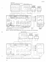
STATUS PA h EL
COOL I NG ONLY
ELECTRIC HEAT 2SP04700924
GAS H EAT IG4001 2SP04700724
[,AS HEAT 1G560, G800) 2SP04700624
ROOM THERMOSTATCOOL INGIHEATING
2TH047001
824
NIGHT SETBACK
THE R MOST AT
2TH 13700424
NIGHT SETBACK
SWITCH “ “
20N04 700101
2SW,
9TH
/
v
H
114
115
D
g
119
105
1
k
T H1
TH2
TH3
TH4
TH5
P
e
F
-~
FVSU* S1,1-
LA
1
L, , “.
1201
r~$,[ / ,
D
o0
, I’h:!;
p______
1
s
6 a
..
r H
7
2
I
r
r
s
2
2
S
c
PR IN TED
CIRCUIT
BOARD
t
t
m
j
FIG. 11
r
w
1
C
a
t
J
c
a 7 D
Id s
W
T
2
T
SOL ID STATE
CONTROL
LN UNIT)
h
c
C
S
S
C
W
S
P
—
ROO*,I THE RKIOSTAT “
COOL ING IHEATING
2TH047001
824 WITH SUBBASE 2SB04700224
PJIGHT SETBACK
THE RMOSTAT
2TH1 3700424
h IGHT SE TBAC K
S,”, ITCH -. —
2DP.04 700101
9TH
v ,
2si’d
3
-“rl
m
D
119
105
2.--!
,.
,,,
,—+
I
J2J
I
9
5
TABLE 3 – E
v
I
C
C
Motors (1 Phase)
Blw.
I Nominal I
I
Tons* RLA LRA volts
Motors (1 Phase)
I
HP
FLA
volts
HP’
FLA
Ampa- Over
~ City Curr.
FLA Amps Oev.]
Min.
Wire
Sizez
volts
Hp”
-
-
-
-
-
-
-
-
-
3
-
–
-
4
0
D
Without Exhaust
Air
9
DSC300
with Exhaust
A!r
3
9
4
DSC360
28A 230
Without Exhaust
Alr
J
-
-
-
–
-
–
-
-
-
2
-
-
–
2
DSC360
With Exhaust
Air
42
235
(2) 4.2
225
100
2
i
2
1
DSC480
Without Exhaust
Air
-
-
-
-
-
-
-
-
-
1
-
-
-
2
17A 208
DSC480
With Exhaust
Alr
2
1
“Quantl!y
per unfit
1 Oual element, t !me delay fuse or !nverse t(me clrcu(t breakers
2 Based on three 75°C Insulated copper conductors
steel comfu17
3 A 575 to 4fj(J “13 [ t,ansf~,mer
,s ~Ir“vIded for these co ”denser a“d pxhaust
10
far, mo~~rs
CES
cONOENSER
COIL
Ml NIMUM
FRONT
Control
CLEARANCES
36”
Box Side
REAR
L
S
Condenser
RIGHT
CoIl
36”
cooling
Only
Units
Electrlc
Heat
Units
Gas Heat
/
36”
Units
90”
120”
r
dlmens!ons
are sub]ect
Certlfled
I
‘
36”
B
TOP
All
I
S
are
in
to change
dimensions
Inches
without
/
‘;~’::::t::’’%
They
notice
WIII be provided
upon request.
I by
tself
I bottom
to
supply
and return
a[r
open (rigs more clearly
OIL
I
L
LL
1 Heating
z Heating
I- -
TVPF
!
-
I
.a-D, o n“
OptIon
Option
FIG. 12 –
G560
G400
U
1
3008360,480
---
4. I /2 Dia. Sleeve
AA
!
u
O
H
1
-..
\
Gas Heat Pipln9
fi--..,ll
Ml;.;””
,
& G800
D
11
530
25. N1
Refer to the fO]k)~lJlg d
cent rol wiring inf{ll matlon.
instructions
material. Ceiling return grilles should be Iucated a minimum
of 12 feet from the end uf t be suund chamber. I n every installation a return tilr duct must be installed to the umt.
t’or zdd]tiumrl
- Form 6
F“orm 530.1 1-N 10.1
—F
5
Flrest~t
Low Ambient Kit
Fl LTERS
All filters being used in these units are 2“ thick. Tbruwaway
filters or 55% efficient bag type 1ilters are ava]lable JS l~ctory
options. Cleanable filters or 30’7{efficient throwaway 1ilters
are avadable as accessories.The cleanable filters have an alummum mesh media that may be cleaned m hot water ur steam,
reol[ed and reused indefinitely. The 30’X and 55’2 efficient
filters are available to meet speclficatiorrs for Improved air
f]lt ratiun. Refer to Table 4 fur filter siie~ mId quantities,
5
F
Form 530,1 I -N1O.4
DUCT CONNECTIONS
The supply and return air duct can be connected to the support fingles which are part of the roof curb package. This
allows the installation of the duct work and roof curb before
instaibng the urril, All duct connections are contained wlthm the roof curb. Refer to Fig. 1.3 for duct connection dimensions for the bottom side-by-side arrange ment.
TABLE 4 – FI
Refer to Form 55.70-N 1 for suggested means of instalhng
and insulating ducts.
I
I
Unit
Model
I
When a unit IS used with a ceding plenum return air system,
sound may be t runsmitted from the unit thru the ceiling to
the conditioned space. For such apphcatluns, there must be
a sound absorption chamber installed cm the umt return alr
sound generated by
relet as shown 111Figure 14. [n this w
DSC360
——
1
1
-
3
,1
1,
‘–
I
A
L
1
d
4
6
\
I
I
-
2 X 20X 25
2 x 20 x 20
2 X 20X 25
2x
I,
(4)
(4)
(4)
(4)
(5)
12X
12 X
12 X
12 X
12X
X
1
1
——
55%
f
l
20 X
24 X
20X
24 X
20X
24 X
24
24
24
24
24
24
3
- I-] ,- - - - - ‘L.”‘m
-“;R‘“ II
u
T
C
( 6)
I 9)
( 6)
(12)
DSC480
L
I
2“Throwaway
2“Cleanable
2“
2 X 20X 25
I
1
A
, ~
“
II
,,,4
~
“
; ‘1 ;
D
I
R
C
I
C
L
.,
3
~
.
,..
w,,,)
b
RH E
e..
h r.olc.
o
,.O,,,
”,,
,
,
,..
,h.
,,0!,)
”e.i
, ,,..
rbacce,
” .
nro,.rl
,
V
!,,.!
’or,
b
curt>
,kak
,.
,>,>6+
“
“.,,
3
1
2
“r...”!
(.,
!“,.
17
([>SC3U03
1201 2 IDS( 480!
!
R
!..
-
-’
V
.. . . .
FIG. 13 – DUCT CONNECTIONS
R
A
A
S
C
t
C
P
S
o
C
i
~
—
R
~
R
—
R
I
the unit is absorbed-in the chamber and not transmitted to
the conditioned space. The chamber may be constructed {f
fiberglass duct or metal duct hned with sound absurptwn
,
C
A
A
G
M
t
-
R
A
L
FIG. 14 – SOUND Absorption
CHAMBER
CES
530.25-N1
ECONOMIZER RAIN HOOD OPTION
+
be assembled to the unit per the assembly instructions in
Form 530.25-N 1.3.
The out do[)r and return alr dampers, the spring-return dan~per Jctuator, the linkage, the enthti]py c}mngeover control,
the rimed tiir temperature cxmtrol and the mmimum position
potentiometer with manual auto switc}] are factory mounted
as part of t be economue[ optmn. The rain hood is shipped
m J separale package and must be assembled to the unit per
the assembly instructions in Form 530.25-N 1.4.
CAUTIO.}’ ,})ttwr~)peratethe unit )vi[hmf itz~tullingthe
hlxd or moisture will be duwn into the utlit.
FIXED OUTSIDE AIR RAIN HOOD
The fixed outdoor alr d~nlpet with i manual tidjustment arm
M t;Ict(~Iy mounted on all units without the economizer option. The rain h(md is shipped in I septir~te pachage and must
CA UTIOI\’:Ifretreroperate
the unit without instaflirrgrite
hood (v moistitre itif{ be draiivl it~tothe utlit.
EXHAUST Al R RAIN HOOD OPTION
The barometric exhaust dampers, the powered propeller exhaust fan and the damper motor end switch are factory minstalled
and wired as part of the exhaust olr option. The rain
hood IS shipped in a separate package and must be assembled
to the unit per the ~ssembly Instructions in FOIm 530.25-N 1.2
.L’0T15’ The exiraust hood (or tiw DSC 480 is shipped [Mtit-()
Patkages.
CAUTIOAF:I\relleroperate the utlit wtithouritlstallitlgthe
fmxr’ or f~mist[trc\\[If bc drauw itlto the unit.
OPERATION
ELECTRO-MECHANICAL
CONTROLS
The t)petat]on of these un]ts can be d]vided m!{) f{)uI systems.
1.
2.
3.
4.
-
Economi,w] System ( ~lpliorral)
1leatlng Systcm (opt]~)ndl)
(’oo]]ng System
l:~haust Air (optmnal)
ECONOMIZER
SYSTEM
The l:con[)n]]/er system c{)ns]stsof:
1
2.
3.
4,
5.
TABLE 5 – ENTHALPY CONTROL (SET POINT “B”)
outdoor ~nd ret urn uu dampers.
Dampel Actuotor (Spring Return).
Enthalpy Contr[)] 5TII.
M]xed Air Controller” - I RI].
klm]mum oot Ndc aII od]ustt~l ( potent iometel ) - 2R11.
The Fct)nomller System provides ~be first st~ge ot c~~[)hng
whenever tile out side :111If COLJIand dI y enough to wt IS(y
the lnterrml ctwlIng demand. Tbe outsde and the I eturn air
dampe]s aI e n]cchan]call~ linhed tind SIe modulated hy the
spIIII: return d;lmper act uutor. As the outside o]r clfin]pers
aIe t)pcned h~rtIIe CLIInpct act u;itol. the I et UIn uir d~mper>
al e closed
When the entl~alpy c~)ntrol ( 5TI 1) sensesoutside alt temp
erst ures pel Table 5, thc out side air dampels close t t) theu
mmlmum pojit M)
II. TIIC lninl mum positItJn ~>ftbe [)ut side
aII dampeIs is det ermlncd by tile wt p(~]nt (JFthe mm imum
t)ut$Ide .III ad Iustor ( ~Rt i ) ](lc’lted In the tel mulal bt)~ 0[
the damper n]otol
+
The outside and the retul n air dampers are controlled by a
pIopoI tmnal type, m]xed-a]r cent] o]ler( 1RI 1) which senses
the tempe]at u]e of the a]r leaving the evaporator coil. The
d~n]pers can modu]ate anywhe] e from theil mmmum outside pos~tion to 1OOV open in fltt empt ing to maintain the
tcmpelature setting of 1R11. If the indoor space temperature
rms, TC2 will close and the No. 1 compressor will be energi/ed through t be 5R relay cont:ic(s to provide second stage
coohng,
OUTDOOR DRY
BULB TEMP. “F
I %
80
60
62
67
71
40
20
10
73
74
DAMPER
LINKAGE
R ELAT 1V E
HUMIDITY
ADJUSTMENT
Aft e] powe] IIVSbeen suppllecl to the unit. the out mle ~nd
I etul n alr d~nlpeIs sht)ulcl be checked to nuike sure they
Opel:1[e II eel} and close t lghtly. I t my be necessary to read)tlst I be III] kage bet we en the ckrmpm motor and the blades
duc t(l Imlsenmg in shipment.
TIw enlh:ilp) contl 01 ( 5-111) 1~f~ctot Y set It sen~esboth
temperal ulc and humldlt }! :Ind \Jrie\ it ~ wt t lng so ,i$ t{) linl]t [he lnt rod uctIon ot’ i~uts]de ;,lr. As not cd in Tab Ie 5 he]ow,
the c(~ntr~ll WI]! nt)t ~11(~~}
(~ut>ldc :111[() cnt CI tbc unit duI Ing
hlgl) llumidl~y ulnd]t II~n\ e\ccpt it (i l~)weI [~ut~ldc tenlpelature. DUI lng dry condl[ l(~n$.:111Is lnt I[)d uLed at o Ili,ghel unlblent,
CES
13
530 .25-N1
2. Turn the rninlrnum outsde ~lr adjustor to the 07 outsde
tiir pos]tmn, All outsde air damper blades should be fully
closed. The linkage connect ing the outwle iIII and the r eturn air darnpels must move freely.
3. Return the mmlrnurn outside alr adjustor to the 1009I
outside alr position tind check for complete freedom of
linkage movement as the ret urn alr dampers close.
4. Set the mmimurn outside alr tid]ustur for the minimum
ventilation requirement of the job,
HEATING SYSTEM
Two different types 01’beat are offered as factory-mounted
opt Ions, Refer to t}le apprwprmte mstruction for m t_ormation on the heating system.
Gas-Fired Heating Opt Ion
Flectrlc Heating Option
- Form 530.25-N 1.1
Form 530.25-N 1.9
COOLING SYSTEM
These units have nominal cooling capacities of 25, 30 and
40 tons. The DSC300 and DSC360 units have one semi-hermetic compressor. Two cooling stages are accomplished by
unloading the compressor. The DSC480 unit has two semihermetic compressors. Two cooling stagesare accomplished
by cycling the individual compressors.
IVOT[<:TIIC)
above t)peratit)nisj))r internlittent jan operation. For continuous op]ratiotl, the fan switch on
the morn thernmtat or the ~tatusIxrne[sh(M~kibe
nwnually closed to energize 7R.
6. Relay contact 1R closes and energl/es 1M c(J1l,which
starts the No. 1 compressor. At the same time, 4M COIIIS
energized to start the condenser fwls.
7. [f the room temperature continues to rise, c(mtact T(’2
doses and energizes 2R coil,
8. On DSC480 units the 2R contacts close, energizing the
2M coil which starts the No. 2 compressor or on DS(’300
and DSC360 units the 2R contacts close de-energizing
the compressor unloading solen[)ld which kinds the ct)mpresser.
9. The compressor short cycle time and low voltage protection is part of the solid state compressor protection
module. 1[ prevents a compressor from starting unless it
has been off for five minutes. It also monitors the v[)ltage of the 120 volt cent rol circuit and will shut down
the compressor if the 120 volt control voltage drops below 85+4.5 volts,
10 To rna]ntain sufficient head pressure during low ambient
operation. condenser fan No, 1 on the DSC 300 unit and
condenser fans No, 1 and No. 2 on the DSC 360 and DSC
480 units will be Lle-cnergl/ed by ITH. Condenser fan
No. 2 on the DSC300 unit tind condenser fans No. 3 and
4 on the DSC360 and DSC’480 will be Llc-energved by
2TH (see Table 6).
Normal sequence of operation is os follows:
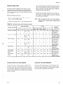
EXHAUST
1, Power is supplied to the unit through the disconnect
switch. The swlt cl] can be field installed or factoryinstalled as an option.
2. As soon as power IS supphed to the unit, the compressor
crankcase heaters 1TI { (and 2T1 I ) WII1 be enelgi~ed,
CAUTION: Do m)t attempt to start ttw cc)ntpressors
Wi[jjc)li[at [east~ /lorirs~)j~rankc,asc~
jt~at
or c~)nlpressordut)rage}t’i[[occur
3. The system switch on the room thermostat or the stfitus
panel must be in the ALITO or COOL posltmn to complete the circuit between the terminals 119 and 103/RC
AIR SYSTEM
The exhaust air fans are energiled by nuinually closlng a circuit between termmals 60 and 64 of terminal block 2TB or
aut orntrtically by an end switch on the economizer damper
mot or, As the economl~e r damper open$, it closes the end
swltcb on the dtiroper motor and turns (m the exlla USI aIr
fans. The degree of blade [)~nlng at which the exhaust f’an~
are energl~ed can be adjusted by the folk~wlng procedure.
1. Use the black scale plate as an indlcatc)r of motor position”
for swlt ch operation.”
? Loosen the thumb nut and the
-.
cam
lock]ng screws.
3 Set the opclationa[ and dii (erent lal c~n]~.
4. On demand of the rotirn thel-mos[at for cooling, contact
TC I closes and energl~es I R coil.
5, An internal connection in the thermostat or status panel
energizes 7R cod. 7R contact closes energuing 3M cod.
3M contacts close, starting the sLIpply alr fan motor. After an adequate air flow ISestablished, 5 LP closes to energize 6R cod. 6R contact closes m the compressor control circuit,
14
4. Check swltcb adjustment by muving the ~dJustor .2RII to
move the motor. Swit CII should click when desll ed make
and break points are lined up with index mark :ind t IIe
exhaust fon stx)uId st~rt and stop.
po~treris CY)IItUrC
led t{)[ho $1%’i[c’h.
h51RI\’1,1’G ]~{) L$cj[[
5. T]gbten thumb nut,
CES
530.25-N1
SOLID STATE CONTROLS
-
A Honeywell W973 solid state Ioglc panel controls the econcrmi~,ermotor and stagesof coohng and heating in response
to a signal from a dual set point thermostat located in the
controlled space or a dual set point transmitter with a remote
sensor located in the controlled space. To maintain stable
space temperatures, the ]oglc panel balances the space thermostat demand s]gnal against the system output. System output
is measured by a temperature sensor located on the discharge
alr duct. The comblned demand and output signals determine
position
irnd the number of heat]ng or coolthe economl/er
ing stagesenerg]zed. The discharge sensor also provides a posit ive modulating low limit signal to the logic panel, insuring
that the economizer will modulate closed if discharge air gets
too cold.
On a power failure, all stages go off and the damper motor
goes to the OYoutside air pos]t]on. When power is restored,
the required stages sequence on w]tb a time delay between
stages.
The outdoor and return alr dampers are controlled by the
logic panel. The discharge sensor acts as a modulating low
limit which sensesthe temperature of the air leaving [he
evaporator coil. If at any time during the cooilng cycle the
dls.chargeair temperature drops to 62” F, the econormzer
motor starts to modulate closed. The economizer motor
will be at minimum position when discharge air temperature is 50° F,
If the economizer cannot satisfy the space demand for
cooling, mechanical cooling stages are energj?ed as needed.
DAMPER LINKAGE ADJUSTMENT
After power has been supphed to the unit. the outside and
return air dampers should be checked to make sure they
operate freely and close tightly. It may be necessary to readjust the linkage between the damper motor and the blades
due to loosening in shipment.
Readjust linkage as follows:
The operation of these umts cun be dwided into four
systems.
1.
2.
3.
4.
-
1 Turn the minimum outside air adjustor to the 100% outside air position. Al] return air damper blades should be
fully closed. Be sure that the spring-return damper actuator has completed its stroke (stopped running). If not,
loosen the drive rod bolt and let the damper motor drive
Economizer System (optional)
I Ieat ing System (optional)
Cooling System
Exhaust Air (optional)
ECONOMIZER SYSTEM
the crankarm until the motor stops running. Retighten
the drive rod bolt to secure the drive rod.
‘-J
.
Turn the minimum outside alr adjustor to the 0% outside
air position. All outside air damper blades should be fully
closed. The linkage connecting the outside air and the return air dampers must move freely.
3
Return the minimum outside air adjustor to the 100%
outside air position and check for complete freedom of
linkage movement as the return air dampers close.
4
Set the minimum outside air adjustor for the minimum
ventilation requirement of the job.
The E.conomiyer System consists of:
Outdoor and return air dampers.
Damper Actuator (Spring Return).
Enthalpy Control - 5TH.
Minimum outdoor alr adjustor (potent mneter) - 2RH.
The Economizer system provides the first stage of cooling
whenever the outdoor air is cool and dry enough to satisfy
the internal cooling demand. The outdoor and the return
au dampers are mechanically linked and are mounted by
the spring return damper actuator. As the outdoor au dampers are opened by the damper actuator the re@rrnalr dampers are closed.
When the enthalpy cent rot (5TH) sensesoutdoor alr temperatures per Table 5, the outdoor air dampers close to then
minimum position. The minimum position of the outdoor
air dampers is determined by the set point of the minimum
outdoor air adjustor ( 2RH). The minimum outdoor air adjuster is factory mounted in the top of the damper motor.
L
The enthalpy control (5TH) is factory set. It sensesboth
temperature and humidity and varies its setting so as to
limit the introduction of outdoor air. As noted in Table 5,
the control will not allow outdoor air to enter the unit
during high hum]dity conditions except at a lower outdoor
temperature. During dry conditions, air is introduced at a
higher ambient.
CES
HEATING SYSTEM
Two different types of heat are offered as factory-mounted
options. Refer to the appropriate instruction for information on the heating system.
Gas-Fired Heating Option
Electric Heating Option
– Form 530.25 -NI.1
– Form 530.25 -N1.9
COOLING SYSTEM
These units have nominal cooling capacities of 25, 30 and
40 tons. The DSC300 and DSC360 units have one semi-hermetic compressor. Two cooling stages are accomplished by
unloading the compressor. The DSC480 unit has two semihermetic compressors. Two cooling stages are accomplished
by cycling the individual compressors.
15
5
25-N1
When the tcn]pertil ure III the corldlt]flned space tlws :ib~J\e
the thermostats c{}{)llrlgset p~~lnt.the thermosttit sends a
mt)dul~tmg w)lttige stgr)~lto t be l(~gIcpane]. The therrnostat
slgnaI IS mocllt ied b} J sign.11t Iom t}le dIschJrge sensor,
which is mounted In the discll~fge air duct t o protrde Qntwlpatlorl to the systcm TIIe logic p~nel responds to the
combmed t Iwl mostJt cilsch,irgesensor signtil by activating
the nnnlrnum onwunl 01’c~xlllng to wtlsty’ the thertnostdt
demdnd.
10 T() mtilnt~lrl suff ]ctcnt head pressure during low ~rnblcnt
oper:it ion conden wr ffin N(). i on the DS( ’300 unl t and
c(]nderlset Ltrl\ No. 1 and 2 on the 1)S(’.360 ~nd 1) S(’480
units WIII be de-energved b} 1T] I (we ‘l-uble ()) (-ondcn se] ton No. 2 on the DS(’300 unlt and condcn~cr f:ins N()
3 :tnd 4011 the DSC360 and DS(’480 urll(i WI1l be de-cnetglzed by 2TI i (see Table 6).
Normal sequence 01 ~]pcra[I{>rlIS as 1’(IIIows
1TH
UNIT
1. Power IS supphed to the un[t through the dIsc{Innect
swlt ch. The SJJlt CII cJn be I’lelcl-installed <lr fsctory-ln stulled as J n op[ l{)rl.
DSC300
———
DSC360
---–
-
DSC480
55 + 6“ F
2TH
25 + 6°F
55 + 6<’F
25 + 6“ F
55 + 6°F
35 + 6“ F
a. As soon JS pt~weI is supphed t() the unit the cornpreSsor
‘..
CIankase hedters 1T} I [and 2TH) will be energized.
EXHAUST
CX L’TI()’v”
D(J1101atte)tu)t I()start [iI(>cottrurcsw)rs\t’ilh(JI([(If [casr S hollrs OJo-at]kc,aseh
t or CY)IIIpr<’w)rdat)la<yc
ltvli (wcur.
3. Tile system swItch on [he r(l~lnl tbermost:it or the stdtus
panel most be in the ALIT() or (’00[
posltlon to complete the clrcult between the [erminti]s I I 9 and 103 R(.
4. On demand of the roon) thermt~st~t for coollng the
“COOI 1“ contacts on the logic panel close ond energl~es 1R COII.
5. An intern~l connect i~~nIII the thernmstat or status panel
ener.gi~esthe 7 R cod. 7 R contact closes energlzmg ~%1
coil. 3M contacts close, starting the supply air fan motor
After an adequate olr flow is est~blished, 5 LP closes to
energue 6R cml. 6R cont~ct closes in I he compI essor
con[ rot CIIcult.
,}rOTf:’: The abotv opct-a[a)t)ISjbr itl[t~rtt)i[tctztjail operatio)l. I’r)r(’(Jflfi/u((J//s
f)p(’raffo}f,fiw JiIfISW’IIL
h
(MIthe roor?lt}wttlostat or [he s[atm pattcl hh(mki
be ttrat~uail~closed [I)ctlt>rgize7R.
Al R SYSTEM
The e~haust :iil fans ~rc energized by manually clo~irlg a clrCU1[between tel rnlnaIS 60 and 64 of termlna 1block 2Tfl or
JLIt~)matLcally be an end switch 011t IIC cc(In(JnII/e r dampcI
mot or. As tbe ecorlonli/cr daroper opens. it clt)$es tIIe cnd
sw’ltch {m 1he darnpel mot (JI and [ UIn$ on t]Ic ek haUS( aIr
lan > The degIee of blade opening ,it wllicli tile cxh,iu~t fan $
aI c enel gljed can be tidjusted by the foik)wing pI ocedurc
1
7
-.
IISC (he bltick scale plate a~ an lndlcatot of nlotol” p(IsIl lon
fol $Wltch Opelat 100.
Ltloser) tile tIIumb nut and the can] k)cklng SCICWJ
3. Set the opel atl(]nll and dlffe Ient lal canl~.
4. (’heck switch acllu>tment by nN)v Ingthe adj(lst(]r 2 KI I to
Inove the motor. .Swltch should click when clcsmd make
~nd bI etik point\ JI c lined up w’}tII Inclex nl,il k tind tIIe
e,khdust ton should ~tart and \t op.
ro [k’ jtt[l(il
i~ILIR.I/,L’(;. 1~() ~(lj[ polt,c,t if ( otritc,ctcd
5. Tighten thumb nut.
~nd eneigl~es 1M CL)II,wluch
6. Relay c(mttict 1R CIOSCS
starts t hc N’o. I compressor. At the same time, 4M is energized to start the condenser fans
SUPPLY
7. If the room tenlperature continues to rise. the “COOI 2“
contacts on the lt~gicpane] close and energues 2 R COII,
Knowing the required CFM, [he unit optlonsl and tlie static
I eslstances (~fhot h t lie S(Ippl} and t l~c Iet urn au duct s>stems, the RPhl toI the supply all blowcrj can be dc[ct nuned
f’rom the blower performance. (See Ttiblc I I.)
8, On the DS(’480 units the 2R contacts dose, energizing
the ?hl coil which st~rts the No. 2 compressor [~r~)n tie
DSC300 and DS(’360 units the 2R contacts close de-enel gI/Ing the compressor unloadlrlg solenold which lrxrds the
cornpresser.
9. The compressor sl]ort cycle time and low vo]t~ge ptotect ion IS part of the sohd st~te compressor protection module. It prevents a compressor from starting unless it has
been off for five minutes, It also monitors the voltage of’
the 120 volt control circuit and will shut down the compressor it’ the 120 volt control voltage drops below 85f4.5
volts.
16
AIR
BLOWER
ADJUSTMENT
Knowing t}~erequired blower RPM and the blower motor
11P, the ~ettulg (t urns open) for the supply alr motor pIIllcy
can be det ermmecl from T~b Ie 7. The 20 I {P drive i or the
DS(’480 has J fixed mott)r pulley and a flxed speed,
Lach motor pulley has
A threaded barrel with two flats (or notc}lecf recesses)
180 degrees apart.
hither one or two movable flanges, each WIIII two set
screws 180 degrees apart.
C
( ES
—
530.25-N1
-
After the movable flange (or flanges) has been rotated to
the proper number of “turns open”, the set screws should
be tightened against the flats on the barrel to lock the nlovable flange in place. If the pulley includes a locking collar,
the locking collal must be loosened to adjust the setting of
t}le movable flange.
To determine the deflection distance from normal position use a straight edge from sheave to sheave as a
reference line.
Note the fcrllowing:
BELT
SECTION
“B”
“c”
1. The supply irlr CFM must be within the limitations
shown in Table 1.
2. Both movable flanges on a 2-groove pulley must be adjusted to the same setting (turns open) to balance the
loading on both belts.
TABLE
7 –SUPPLY
AIR SYSTEM ADJUSTMENT
The recommended deflection force is as follows:
DEFLECTION FORCE (LBS,)
MINIMUM
MAXIMUM
4
-
11
5
14
1
e. Tension new belts at the max. deflection force recommended for the belt section. Check the belt tension at
least two times during the first 24 hrs. of operation.
Any re-tensioning should fall between the min. and
max. deflection force values.
f. After adjusting, retighten nuts(A).
-
TURNS
MODEL
7-1/2
OPENI
6
913
950
5
4“
987
DSC300
1024
3
1061
——.2
1098
1
—
6
—
5
—
4
DSC360
—
3
—
2
—
1
—
6
5-‘-~ –
D.-.C480 --- 4–
s– .– ..-. :— 2“
1
–
—
RPM
10
1025
1062
1099
1136
1173
1210
780
812
844
876
908
940
—
–
–:
‘–
—
15
–
–
–
–
–
–
924
962
1000
1038
1076
1114
924
962
1000
1038
1076
1114
20
–
–
–
–
–
–
–
–
–
–
–
–
–
–
–
–
–
11892
\
‘NEVER
\/
(i
LOOSEN
(c)
●
FIG. 15 – TYPICAL MOTOR MOUNTING ASSEMBLY
1 Pulleys can be adjusted In half turn Increments
2 F(xed pulleys, no adjustment.
5. All pulleys are factory aligned.
3. All pulleys can be adjusted in halt-tu[n increments.
4. The tension on each belt slxrll be adjusteci per the fol-
6. All supply air motor pulleys are factory set at 2 “turns
open”.
lowlng procedure. See E“lgure15.
After the pre-start check Ilst has been completed:
J. Loosen two nuts ( A).
Start the supply air blowers.
b. Adjust by turning (B).
c. Never loosen nuts (C).
d. Using:1 belt tension checker, opply a perpendicular
force to one belt ~t the rmdpomt of the span as shown
The deflectmn force should be applied until the
specified deflection distance is obtained.
The deflection distance equals 1/64” per mch of span
length.
CES
Adjust the resistances in both the supply and the return
duct systems to balance the air distribution throughout
the conditioned space. The job specifications may require that this balancing be done by someone other than
the equipment installer.
To check the supply air CFM after the initial balancing has
been comnleted:
1, Drill two 5/ 16“ boles ( A & B) as shown in Figure 16.
17
530.25-N1
2. Install two 1/4” O.D. tubes, one between the filters and
the air entering side of the evaporator coil and one between the supply air blower(s) and the air leaving side
of the evaporator coil.
5/1 6“ DIA
—
—
5116“ DIA.
/
B
o \
=
IJNIT
DRAIN
—
—
1
k
80
90
100
PERCENT NOMINAL
I
RIGHT END
VIEW
+0
30”
MODEL
-t-
33”
FIG. 16 – HOLE LOCATIONS FOR SUPPLY AIR
CFM CHECK
DSC300
DSC360
DSC480
I
80
8000
9600
‘1 2800
I io
CFM
% OF NOM I NA L CFM
110
100
90
C F .M.
9000
10800
14400
10000
12000
16000
130
120
11000
13200
17600
120
t 2000
14400
19200-
FIG. 17 – PRESSUREDROP ACROSS A DRY
NOTE: To@ a .proper
. static pressure reading, the sensing
tubes should (A) be inserted through the rear or contitwsate drain side of the unit (B) be lttcnted
approxittwtel>’6 inches awa.t’jrorn the coil surjace
and as close to the center c)]”
[he coil heigh[as possible (C) e.rtend into the utut appro.~itnate(vt12
inches.
3. Make sure that the access panels for both the supply air
blower motor and the filters are ptirtially secured. These
panels do not have to be secured where the 1/4 inch tubes
enter the uruts because the blow’er and f“iltercrrmpart men[s
operate at a negatwe pressure.
4, Make sure that the tube openings are perpendicular to the
air flow so that veloclt y pressure WI]] not affect the static
pressure readings.
C4
UTIOiV [frhis method is used, the h<~kymust he sealed
wifh dot plugs (P/,J’029-13880) or equit’alent
t[]prcrtwt mois?urcjkotn leaking into thc~[[nit.
MASTER PRINTED CIRCUIT BOARD & PLUG-IN
RE LAY ASSEMBLY
All of the control”reloys that are required for unit operation
are mounted on the printed clrcult bool d Fgure 9, 10 or I 1
shows this assembly W}IICII IS located In the ma]n cent r[]l pan
el. All of the relays are of the plug-in val iet}, II(J wil ]ng COIE
nections have to be removed to replace a relay. S]nce the relays are transparent, the mechanical contact switclung can be
observed f’or easier elect rlcal troubleshoot lng.
The low voltage field wiring IS to be connected along the top
of the printed circuit board at the eyelet connections, Each
termmal IS marked both numerlca]ly and with letters corresponding to the rooni thermostat for easier installation
18
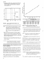
EVAPORATOR COIL VS SUPPLY AIR CFM
5. Using an ~nclined manometer, determine the pressure drop
across a dry evaporator cod, Since the moisture on tin evaporator coi] may vary greatly, measuring the pressure drop
across a wet coI] under field cond It Ions WOUICIbe Inticcurate.
IJ10T15’Discc)tmectthe <ontpre,sw~t-s
bi~fi)retuking ant tesl
measuwtncnts to assut-da tlrl’ el’apc]rutorcoi[.
6. Knt)wlng the pressure drop across a dry coil, the actual
(’FM thr[)ug}~ the unit cun be determined iron] the crrrvc
in Figure 17.
If the CFM ISabove or below tlte specified value, t}lc supply
alr motor pu]ley may have to be readjusted. After (me hour
of operat [on, check ail belt\ and pulleys for t @lt nes~and
aIIgntnent.
Two lumper p]LIgs.one led and one w]ute, ~1e k)cated al tite
top of the board. When they are [emo~ ed ~nd replaced wltb
the connectors of the service analyzer, the analy/er WIII l)verI ide the rm~m thermostat. All s)stem func[l{)ns suCII .Is IICUIing, coo]ing, econonllzer, and nlght set-back can be slrnul~ted.
Mall[lnct I(,II mdIctit[)I llgl)t~ irIe provided to de[ermme WIIICII
system 110sm~l[ unctioned.
C-AUTIO,}’, Whenremo~mg the cotltlector.ro~”thescrtw
attal~)zer,the two juniper plugs ((me red atld (ml’
)tyhite)must be reinstalled into rheir proper w)ckets b~;fiw the s~~[etncanjunc[IcNI.
The procedule for troubleslumt mg o unit with a service analy/er ctmnectecl to lts pr~nteclCIIcult blurcl IS outlined below.
CES
530.25-N1
S
A
s
m
p
a
a
t
w
c
u
o
c
o
o
c
P
C
u
c
s
p
h
e
I
f
c
c
S
v
(
R
A
p
m
1
c
m
a
w
c
p
b
d
s
p
w
8– S
1
c
c
P
p
T
R
l
o
f
l
s
l
B
c
c
1
A
j
c
F
C
SWITCH POSITION
s
s
LIGHTS
PROPER
OPERATION
SYSTEM F UNCTION
SYSTEM
HEAT
COOL
FAN
N.S.B
Economizer 1st Stage
cool
off
St 1
EcOn
Auto
On
off
Economizer 2nd Stage
cool
off
St. 1
St 2
Econ
Auto
On
off
Compr 1st Stage
cool
off
St. 1
Cpr
Auto
On
off
Compr 2nd Stage
cool
off
St. 1
St 2
Cpr
Auto
On
off
Off
~AutO\
Off
ECON.
w
Heat 1st Stage
-+=+
A
a
a
L
f
a
Off
On
off
T
off
off
On
On
+
off
off
Off
off
c
b
On
p
a
L
w
v
On
I
T
off
off
off
off
Heat & fan omy
operate from
N ,S.6 Thermostat
P
F
r
d
b
a
F
r
On
Off
+
I
On
I
Off
off
off
On
E
o
o
s
p
o
A
Fan & Compr #l
on, w)th O S A.
dampers open to
mln posltlon
Fan, Compr % ,2,
run wtth O S.A
dampers open to
mln pos(tlon.
Heat section
operates on
reduced capacity.
Heat sect(on oper.
ates full capac!ty
No cooling, econ,
or fan operation
off
off
O
On
off
N(ght Setback
(heat}
F
Fan on, O S.A
damper~ operate
to setting of
m{xed alr control
Fan on, Compr #1
on, O.S. A dampers
operate to sett(ng of
mixed alr control
On
1
N!ght Setback
(cool )
On
Off
On
Heat 2nd Stage
ON
off
off
FAN
T
-
m
a
a
c
p
r
a
e
s
e
b
c
f
d
\
CES
19
530.25-N1
1
I
I
1
I
0
I
.!
I
BLADE
POSITION
0
0
0
0
0
B
10
40
30
20
% OUTSIDE
F
– F
O
50
AIR
A
0
0
0
0.
DSC 300/360
UN
DSC 480 UNIT
l-s
0
3000
4000
5000
1
,
6000
7000
EXHAUST
– E
8000
9000
10000
11000
AIR CFM
P
CES
530 .25-N1
T
-
9–
M
D
I
B
M
I
R
A
M
B
P
P
‘
D
I
9
1
7
9
9
P
D
I
I
-%w%[
C
4
a
1
1
1
1
1
1
1
D
N
L
I
I
1
1
2
-
6
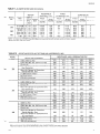
NOTE All motors are 1;
A, Have Solld Bases,and require starters w!th overloads, which are factor~ supplled
●2O HP dr(ve has a f(xed motor pulley
T
–
O
M
O
2
2
2
2
2
A
R
A
G
E
Q
@D
E
Exhaust
.
Air
R
D
E
D
E
C
R
S
E
F
F
C
I
I
G
E
Heat
I
E
I
Fvha,
,ct 7Air
0!>””..
.,!
e
1777
I
I-).66
I,
v-R-
D
E
D
E
I
C
I
R
S
E
.
,
,.
y.-
.-,
I1
.
C
E
E
R
I
I
F
Ran TunP F )ltPrcl
.-r”=
----
.-
A
I
nl R
-
E
D
E
D
E
S
R
C
SOYOEfficient
Filtersl
F
C
1These resistances Include a deduction for 2“ throwaway or cleanable filters
2Add the$,eresistance values to the available static pressure shown in blower performance data table
CES
21
5
25-N1
—
—
EL=I= z =E=i=
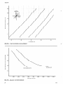
TABLE 11 –SUPPLY AIR BLOWER PERFORMANCE
●
MODEL DSC300
—
CFM
Blower
I
BHP I KW
SP
g~o
950
-1000
–1050
11000
10000
9000
8000
RPM
SP I BHP \ KW
BHP I KW
SP
0.88 ——.—
4.00 J 3.50
1.08 4.43 \ 3.86
1.30 4.86 4.23
1.52 5.38 T4.67
1.75 5.93 1 5.l&
1.97 6.43 5.60
2.20 6.93 6.06
1100
1150
1200
El
0.17 6.65
%.42 7.22
0.69 ‘7.87
0.95 I 8.56
1.22 “9m
1.49 9.87
7 1 /2 HP Moror ~nd Drive
ma XI mum 8 65 HP
12000
BHP ] KW
SP
SP
BHP I KW
,
—
–
I –
5.80)1
6.34
——
6.97 0.27 8.85
7.29 0.55
9.52
7.89 0.84 10.23
8.42
1.11 10.86
—
1
I
–
7.53
8.10
8.76
9.40
10 HP Motor and Dr(ve
maximum
11 5 HP
0
MODEL DSC360
Blower
RPM
SP
A ,.-
---
LJuu
u.Y/
9600
BHP
. -.
I
4.
KW
. --
I I
I 4.UY
5.31 4.59
1.40 5.88 5.06
1.67 6.60 5.67
1.98‘ 7.38 / 6,33
2,23 8.04 I 6.87
2.50 i 8.63 ] 7.35
n
10 HP Motor
maximum
SP
- --
1 U. lb
1.18
850900
950
1000
1050
1100
10800
BHP ] KW
- .. -.
I
9.40
I
4. f I
1.00
1.24
1.53
6.12
6.79
7.73
5.26
5.83
6.62
1.82
2.09
2.38
8.29 / 7.0~
9.00 [ 7.86
9.65 ! 8.22
SP
,. . .
I
U.4U I
Q~4
1.00
1.29
CFM
12000
BHP
KW
,. . - a’.
tJ I n I h fII
6.01
3.UY
7.50
8.36
6.43
7.13
0.95 I 11.15 9.69
1,26 \ 12.12 10.59
1.58 I 13.20 ?1,71
1.5% 9.14
7.77
1.88 9,92 I 8.46
2.17 \ 10.80 ! 9.34
15 HP Motor
and Drive
11.5
13200 ———
14400
——
BHP – KW
SP
BHP ] KW
f
I
1
— II —1—l—-l-l–
SP
max!mum
n
HP
and Dr!ve
17 25 HP
MODEL DSC480
I
IJ!”
CFM
””c,
12800
I
BHP I KW I SP
RPM
SP
14400
16000
BHP I KW
SP
17600
——
BHP
KW
SP
10.03
11,02
11.96
12.86
13.84
14.87
15.57
o
15 HP Motor
max(mum
NOTE
n
and Drive
17.25
HP
5P – Avai Iable Stat!c
Pressure
(n IWG to overcome
the resistance
of add!t(onal
BHP / KW
. I —
SP / BHP I KW
—
-+-
.—
— =-15.45 13.49
–[
—
T
ii42
——
0.76 16.56 14.53
1.10 17,6-1 15.49
-1/lJ
1.76 w
20 HP Motor
maximum
=1--——
–1
-
and Dr(ve
23 HP
un(t opt!ons
and accessories
and anything
external
to
the unit
Un\t
●
resistance
bottom
22
IS based on a “cooling
side x s!de duct
OnlV”
unit with
wet evaporator
COII, 2“ throwaway
or cleanable
filters,
no and/or
f I xed outsrde
a)r, and
connections
r’cc
530.25-N1
START-UP
-
CRANKCASE HEATERS
It is important
that the crankcase heaters be energved 8 hours
before starting the compressors. To energize the crankcase
heaters, the room thermostat or status panel system switch must
be open to prevent the compressor from starting. If a disconnect
switch is installed outside the unit, turn it to “ON”. The nonfused disconnect (optional) located in the unit’s main supply
panel must also be turned ‘ON”.
7. Each refrigeration system has a low pressure cutout ( I LP
for system No. I and 2LP for system No. 2) to shut down
the compressor duc to loss of refrigerant charge or a build
up of frozen condensate on the compressor before the suction valveand are set to open when the suction pressure
drops to 7 psig. These controls WIIIautomatically reset
when the suction pressures rise to 22 psig. The opening of
the low pressure cutouts WI]]activate the lockout circuit.
8. High pressure cutouts ( 1HP for system No. I and 2HP for
CAUTION: Do not attempt to start the compressors without
at least 8 hours ofcrankcase heat or compressor
damage will occur.
system No. 2) are located in each system on the compressor
before the discharge valve. Should a system discharge pressure exceed 398 psig, the control will open and de-energl~e
the compressor, The pressure cutout will close when the
discharge pressure drops to 310 psig. The opening of the
high pressure cutout will activate the lockout circuit. The
high pressure cutouts may open due to a dirty or restricted
condenser coil, loss of air flow or too high an ambient air
temperature.
9. The lockout circuits mentioned above WIIInot be energized
during normal operation because they have a high resistance.
The flow of electricity will normally follow the path of
least resistance through the compressor contractors IM and
2M. lf, however, a low or high pressure cutout opens, the
lockout relay IORor 11R WIIIbe energized. Since the voltage across 10R or 11R WI]]exceed 10OV,the voltage across
1M or 2M will be too low to pull in the contractors.The normally closed contacts of 10R or 11R will open the circuit m
series with the low or high pressure cutout. When these contacts automatically close, the lockout circuit can be reset by
interrupting the control circuit at the room thermostat.
Two advantages are gained by this circuit:
SAFETY AND SERVICE FEATURES
a. Prevents rapid cycling of the compressors which can be
damaging.
b. The alternate use of manual reset cutoffs avoids the problem above but may require an expensive service cL1 to
reset these controls.
10. Freezestat 3TH senses the suction temperature of the No. 1
The control circuit includes the following safety features:
system and will shut down compressor(s) when this temperature drops to 32”F. It will reset automatically at 37°F.
1. The supply air blower motor is protected with manual reset starter overload protectors.
11. The supply air flow must be proven by vacuum switch 5LP.
2. The condenser fan motors have inherent protection.with
In the event the belts on the supply air motor break or the
automatic reset.
supply air motor should be de-energizedby its overload pro3. The primary winding of transformer IT is protected by
tectors, 5LP wdl open and interrupt the cooling, heating
fuse 12FU. The secondary winding and the 115 volt conand economizer control circuits. This assures that the various
trol circuit are protected by fuse 13FU.
modes of operation do not continue without proper air flow.
4. All safety controls in the 115 volt circuit have the “return”
I2. The compressor motor protector(s), 1MP, 2MP will interrupt
or “common’ side of the 1T transformer grounded. Fuse
the compressor control circuit when sensingan overload con13FU will “BLOW”whenever a dangerous condition occurs.
dition. Also an anti-recycle timer is part of this device to preThe un]t casing is also grounded.
vent the compressor from rapid cycling. The compressor will
5. The wlr]ng to each compressor motor, each condenser fan
stay off for five minutes. It also monitors the voltage of the
motor and the supply air blower motor are individually
120 volt control circuit and will shut down the compressor if
fused according to the National Electrical Standards.
the
voltage drops below 85 ~ 4.5 volts.
6. The compressor(s) are protected by a 100 watt immersion
type crankcase heater(s). Heater(s) are energized whenever
13. Oil pressure control switches are installed In the compressor
power ISsupplied to the umt. When the compressor(s) are
circuits. These assure that adequate oil pressure ISpresent to
energized, the heater(s) are turned off.
lubricate the moving parts of the compressor. If pressure IS
not adequate. the switch opens shutting down the compressor.
It is manually reset.
CAUTION: Do not attempt to start the compressors without
at least 8 hours of crankcase heat or compressor
damage will occur.
CES
14, When the pumpdown accessory, Model 2PD04700101, is ]nstalled, the compressor will continue to operate through contact i 2TR-2 after the room thermostat or controller 1ssatisfied.
23
Solenoid 3SOL m the Ilqud IIne ISnow closed and the compressor pumps most 01 the rclrlgcrant out of’the evdpor:itor to
the high side of the syftcm. The sys[cm srrctIon pressure drops
until the low pressure cu[off ( 1LP) opens. This WIIIshrrt down
the compressor and de-energizesthe 12TR relay which opens
12TR-2 to put the opcratlon of’the compressor under the control
of the I R relay. Also prcwnt ISa 12TR-I contact which M closed
when the system is off and provlcfesa bypass circuit to allow contactols 1M and 2M to be actwated In the event the low pressure
cutout has not reset. Without this pumpdown cucuit, it is possible
to have the 011pressure sw[tch (OP/PS) open on IIght load and
short cycle of the comprcwor. Refrigerant floods back to the
compressor on each start-up, foams the oil in the compressor
crankcase and pumps the oil to the condensate cod. The run
times are too short to bring the oIl back [o the compressor so that
eventually [he 011pressure switch opens. This rcqulres re-setting
manually at the unit.
PRE-START CHECK
Before starting the unit, the followingcheck llst should be
completed.
1. Make sure the proper clearances were ccmsidcred.
7
Make sure all foreign matter has been rcmoved from the interior of the unit (tools, constructwrr or shipping materials).
3. Rotate all fans und blower wheels m~nually to check for free
rotation.
4. Check belt tensions and allgnment.
5. Make sure all wiring connectwns are tight.
6. Make sure the avadable power supply and unit nameplate
data agree.
7. Make sure the fuse sizes and the power wire are properly sized.
8. Make sure all controls arc set at their proper set points.
9. Make sure condensate dra]n line IStrapped pcr InstructIons as
indicated with Figure. 4.
‘-.
10. For shipping, the compressor hold-down nuts are
tightened, drawing the mounting feet down to the
shipping stops. After the unit is in its final position,
the four hold-down nuts must be removed to insert
the rubber grommets found in the small parts bag.
Replace the hold-down nuts and tighten until they
start to compress the isolator springs and then give
them an additional half turn.
INITIAL
START-UP
1. SUpply power to the unit through the d]sconncLt~w][ch~1
least 8 hrs. prior to start]ng the compressors,
2. Move the syste]mswitch on the thermostat or the status panel
to the AUTO position.
3. The proper supply air CFM should be established at thts tlmc
with an inclined manometer as outl incd m this Instructmn.
This ISan tmportant part of”the start-up prorxxlurcsince ]t
dtrectly affects nulsancc trip-outs on unit safety controls,
corrdensatc watcr blow-off from tbc evaporator coil, bcarmg
and shaft darna~c, nolsc and vibration.
4. Lower the room thermostat to cncrglzc comprcswr No. 1.
5. With an ammeter, check the compressor and the \upply atr
blower amps to make sure they agree with the unit data plate,
6. Lower the room thermostat to crlergl~ecompressor No. 2. or
ioa,J the comprmsor,
1
(’heck [he con]prc~suramp\ w]th Ihc unit dat~ plate.
!.
8.
.\/ ter approx[ma[ciy 15 mlnutc~ ()! opcru~lon,check tllc IIquId
!Irlc’)I,ghlgl:isw’~i(Jra proper \IquId Iet r]gc>l
ant $c’JIIn c’ac’hof
[he retrlgclJI)[ ~lr~utl(i)
()
NCX1IIILIC;IWthe wttlng 01 tbc room thcrmostu[ unt d the
hc~tlng col~td~!iarc cnergl/cd.
; ().
Retcr t{)[hc prolwr l)catlng ]r)slalldt]un and opcrallorr )n>[ruc( ion ~(II t hc LO I I cc1 hedtlng wqucncc of opcra( Ion,
!1
mlnu tcs. dc\l tcr [hc unlf ha~ bcL,n ()~cratlnti . I or wvcriil
Jnc; gvc lilc md]n
lpuwcIdnd lr)~pcct all 1actor} wtnng
. ,n]~cc[ mIl\ dnu hol tcd ~urfacc~ I or t lfi!)l ncii.
POST-START CHECK LIST
A\ter tllc cntlrc control clrcutt has been cncrguccil check the
following
I Cooling jystcm start-up.
2. Rotation of blower wheels. Ad]ust Ihc wr systetn If ncccssary
per the prt)ccdurcs as outl incd m thts ]nstructlon.
NOTh”: If’the supply uir blower rvta[cs it~the wr(mgdirection,
reverse two oj” the motor lcadbat blower motor cOt~tact(w 3M.
3. Operat]on of the outside and return alr dfimpcrsa$ cxplalncd
under ‘‘DamperLinkage Adjustmcrrt m th]s ]nstructton.
After the un]t ISfunctioning properly, Instruct the owner and
operator on bow to oprate the unit. Replace ail panels bclorc
Ieav}ngthe job s}tc,
-
MAINTENANCE
FILTERS
The filters must be replaced as often as necessary to assure good
au flow and filtering action.
Refer to Figure 1 for filter access IocatIon.
DRAIN PAN
The dram pan should bc mspectcd regularly to assure proper
dra]nagc.
LUBRICATION
The bcar~ngsfor the blower shaft tind the blower lno~{]r~rc pernxrnentlv luhricated find should not reciuirc any addIIIonal 1uhrlCOILS
catlon.
Do not allow dut to accumulate on the evaporator and condenser
BELTS
coil or other parts of the evaporator and condenser clrcu]t. Clean
Maintain belt tension to extend belt life, Rcplacc when s]gnsof
as often as necessary to assure good system performance. Use a
fadurc begtn to appear.
brush, vacuum cleaner attachment or other suitable means.
REFRIGERANT CHARGE R-22
–DSC300
I
oz.
40
DSC360
lb&8 OZ.
D.SC480
I
29 Ibs.d
OZ,
each
SV~
i3YORK”
—
HeattngandAlr Gondltlonmg
P O Box 1592, York PennsytvamaUSA 17405-1592
Subject 10change withoutrwtme. Pmrfed m U S.A
Copyright@by York IntemabormlCorporation t993. All nghtereeewed
CPC 2M t093 t 32
.-,.-. . ..