1
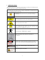
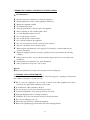
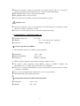
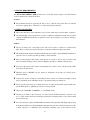
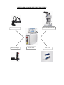
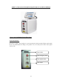
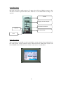
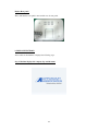
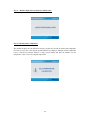
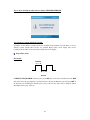
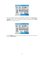
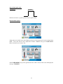
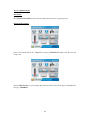
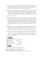
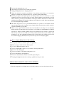
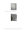
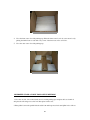
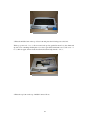
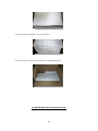
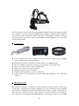
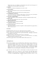
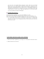
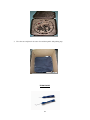
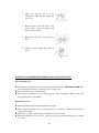
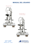
1
TABLE OF CONTENTS
Title
Page No
1.
Introduction.
3
2.
Product Usage.
4
3.
Quality, Reliability And Safety.
4
4.
Safety Precautions.
5
5.
Important Safety & Maintenance Instructions.
6
6.
Warning And Caution For Use.
7
7.
Environmental Condition For Usage, Storage, Package, Transportation And
8
Others.
8.
Cooling Requirement And Location.
9
9.
Safety Procedures And Caution.
9
10.
Green Laser & Delivery Systems.
10
11.
Green Laser Console Working Procedure And Packing Methods
11
12.
Integrated Laser Slit Lamp And Packing Methods
22
13.
Laser Indirect Ophthalmoscope And Packing Methods
29
14.
Endo Probe.
34
15.
Cleaning And Disinfection Information And Maintenance
36
16.
Green Laser Technical Specifications.
37
17.
Integrated Laser Slit Lamp Technical Specifications.
38
18.
LIO Technical Specifications.
39
19.
Laser Basic Slit Lamp Technical Specifications.
40
20.
Trouble Shooting, Product Features, Warranty.
42
21.
Terms And Conditions.
43
Sl.no
2
1. INTRODUCTION:
The AMOGH Plus is proudly well designed. Please read the following information carefully, before
operating the APPASAMY GREEN LASER. APPASAMY ASSOCIATES is responsible for the
safety, reliability and performance of the equipment only, if it is used in accordance with the prescribed
instructions.
Light Amplification by Stimulated Emission of Radiation (LASER) is very much related with our day to
day life. (Green) lasers are used to treat Fundus nerve system when a patient is suffering by vision loss.
These Lasers are coupled with slit lamp, indirect ophthalmoscope and endo probe systems for treatment.
We must be careful while handling these Lasers. Always apply the lowest power needed to obtain the
desired surgical effect. Always focus the aiming beam as carefully as possible to the tissue to be treated.
Never release a laser pulse, if you cannot see the aiming beam reliably in the target area. Switch off the
aiming beam, when the device is not in use.
Fiber optics may not be bent strongly, may kinked or be fastened incompletely, since otherwise the
device could be damaged and / or the patient or user could be injured. All objects within the Laser
hazard area, including the floor, should have diffusely reflecting surfaces or be covered by diffusely
reflecting material. Only the patient to be treated and instructed personnel may stay in the laser hazard
area. The persons must wear laser safety goggles when the laser is in operation. Persons working in the
laser hazard area must be informed about relevant safety regulations and precautions and instructed in
operating the device. The physician need not wear protective eyewear, if he observes the treatment area
through an operating microscope equipped with a physician's safety filter, a laser slit lamp, and the
protective eyewear must have been approved for the wavelength of the laser and the type and intensity of
the laser radiation.
IMPORTANT: This device is designed for use by a certified practitioner.
Apart from those by identified in the instructions in the manual, there are no user- serviceable
parts in this device. APPASAMY ASSOCIATES will retain the direction to advise whether any repairs
may be carried out by external qualified technical personnel, or whether part(s) of the device must be
returned to the manufacturer’s premises for service or repairs to be carried out under warranty or
otherwise, where appropriately qualified technical person are identified. APPASAMY ASSOCIATES
will be available on request for assisting in maintaining or repairing this device.
3
2. PRODUCT USAGE:
Laser treatment (photocoagulation) is used to stop the leakage of blood and fluid into the retina. A
laser beam of light can be used to create small burns in areas of the retina with abnormal blood
vessels to try to seal the leaks.
This is an ophthalmic surgical therapeutic equipment to treat the human eye to stop the blood
seepage in the ruptured blood vessels of Retina due to high pressure. The principles of these
equipments are LASER photocoagulation technique.
Usages of this equipment are Age related macular degeneration, Branch and central retinal vein
occlusions, CMV retinitis, Diabetic retinopathy, Epiretinal membranes (Macular pucker),
Floaters, flashes and Posterior vitreous detachments, Diabetic macular edema, Macular holes,
Macular translocation, Melanoma, Retinal detachment, Proliferative vitreoretinopathy,
Photodynamic therapy, Vitrectomy, Cystoid macular edema, Retinitis pigmentosa, Retinopathy
of prematurity, Retinoschisis, Retinoblastoma, Leber congenital amaurosis, Stargardt's disease,
Cone dystrophy, Cancers in relation to the retina.
3. QUALITY, RELIABILITY AND SAFETY:
This equipment has been designed with an emphasis on quality, reliability and safety. APPASAMY
ASSOCIATES can only accept responsibility for these aspects, provide the following conditions are
met.
Electrical installation of the room or building in which the equipment is to be used must comply
with the regulations specified by the country.
The equipment should be used in accordance with the “Instructions for Use” mentioned in the
operating manual provided by APPASAMY ASSOCIATES.
All modifications and repairs in the equipment have to be carried out by authorized APPASAMY
ASSOCIATES personnel.
The equipment must comply with regulation specified in warning and caution.
4
4.
SAFETY PRECAUTIONS:
Safety pointers in the device are depicted and described there in according to the following categories.
Carefully read these sign codes & follow them when necessary.
The following sign codes describe the degree of danger or damage likely to be incurred in the event
of user error made in ignorance of these codes.
ATTENTION: In the event of user error, product may be damaged.
STICKER AND ICONS
This icon represents the location of laser energy emission.
This icon represents the laser radiation.
Hot parts symbol. This symbol is placed on bulb housing and or other
parts to indicate that they may be hot never touch those parts
immediately after the equipment has been used.
This icon represents “TYPE CLASS 4” equipment.
Number following this symbol indicate the serial number of
the Equipment
It has the content ‘visible and invisible laser radiation-avoid direct
exposer to beam’ ‘wear eye protection medical glass &laser product’
It has the content ‘calibrated tamperproof label warranty void if
removed’
It has the contents like
Change tissue paper for every patient.
5
5. IMPORTANT SAFETY & MAINTENANCE INSTRUCTIONS:
User Maintenance:
Read the instructions carefully before using the equipment.
Unplug the equipment and refer servicing to qualified service personnel under the following
condition.
If the product isn’t able to use even all the troubleshooting has been done in accordance with
the manual.
If the liquid has been spilled into the optics / Equipment.
Regular maintenance for the overall equipment is mandatory.
Handle the equipment carefully.
Touch the key pad gently.
Adopt proper methods to clean the optics and equipment.
Before switching off, turn off LIO regulator knob.
Cover the Equipment when not in use.
Don’t touch the fiber Connector.
Don’t touch the mirror surface in fiber.
Don’t spill any liquid into the equipment.
Don’t use any hazardous solvents to clean the optics and parts.
Only use soft cum dry cloth to clean the device.
When using the instrument after a prolonged period of inactivity, confirm normal and safe
operation beforehand.
If the product has been exposed to rain or water.
Disposal:
Dispose the instrument according to the local disposal and recycling laws.
6. WARNING AND CAUTION FOR USE:
Warnings are intended to alert you the importance of the following proper operating procedures where
risk of injury to the patient or system user exits.
This is a class IV equipment to the avoid risk of electric shock. This equipment must only be
connected to the supply mains with the protective earth.
No modification of this equipment is allowed.
Use only the type of power source that indicated on label.
Connect the Equipment to the properly grounded power outlets.
Unplug the Equipment before servicing / cleaning it.
Confirm the AC power cord meets the relevant local safety standards.
Don’t use the damaged power cord.
Only trained personnel have to handle the equipment.
Remove the equipment plug from the wall outlet before changing the fuse.
6
Check the electrical connections periodically; any defects noticed, like loose connections,
damaged to insulation in the electrical wires etc., should be rectified immediately.
The equipment shell not use in oxygen rich environment.
The equipment shell not use in wed areas.
Do not operate the laser without connected slit lamp which in operation
Caution for Use:
Cautions are intended to alert you the importance of the following proper operating procedures
where risk of injury to the patient or system.
In order to avoid the electric shock; do not handle the plug with wet hand
7. ENVIRONMENTAL CONDITIONS FOR USE:
Operating Temperature
:
0°C ~ 50°C
Humidity
:
35% ~ 95% (without dew condensation)
Air Pressure
:
700 k Pa ~ 1060 k Pa
Storage, Usage Period and Others:
1. Environmental conditions for installation (without package)
Temperature
:
- 40°C ~ 70°C
Relative air Humidity
:
35 0% ~ 95%
Air Pressure
:
600 k Pa ~ 1300 k Pa
2. While storing the equipment, ensure that the following conditions are met
Air pressure, unfair temperature, high humidity, improper ventilation, sunlight, dust,
salty/sulfurous air, etc. will give negative side effect to the equipment.
Do not store or transport the instrument on a slope, uneven surface or in an area where it is subject
to vibrations or instability.
Do not store the instrument where chemicals are stored or gas is generated.
The instrument should be splashed with water.
Packing Environmental Conditions In Transportation
Temperature
:
-40°C ~ 70°C
Humidity
:
10% ~ 90%
7
8. COOLING REQUIREMENTS:
The APPASAMY GREEN LASER system is air–cooled. This system requires a six inch clearance
on all around the laser to allow the air flow.
Location:
The instrument should be positioned in such a way so that the laser beam cannot be directed
towards an opening (Door or Window) or towards any reflective material.
9. SAFETY PROCEDURES:
This section introduces a few elementary steps to follow when using your Laser Photo coagulator.
An understanding of these instructions as well as compliance with them and with the procedures
outlined in ANSI standard Z136.3 is required in order to prevent injury to personnel or damage to
the instrument.
Caution:
Never look directly into a laser light source and avoid exposure to reflected or scattered laser
light. This is a class 4 laser; direct, reflected or scattered from this laser may cause injury.
The treatment beam emitter from this instrument has the potential to ignite flammable materials or
explosives. Do not use this system in proximity to these materials.
Except for the physician and patient, safety glasses are a must for anyone who is present at the
time of treatment. During some procedures it might be advisable to shield the untreated eyes
Never leave the system “ON” when it is unattended. If you want to leave, turn the system “OFF”
and remove the key from it.
When the laser is “READY”, keep it always in “Stand–By” mode unless it is being used to
perform treatment.
Contact lens wearers should use anti-reflection lenses treated for 532nm wavelength. Contact
lenses, particularly those with Plano surfaces, can generate dangerous reflections.
Never open the laser enclosure, as hazardous levels of visible and invisible optical radiation are
present inside. Refer to qualified personnel for service problems.
Observe the “DANGER”,”WARNING” or “CAUTION” labels.
Circuitry is provided for the connection of a remote interlock. When attached to the laser room
door or other actuator the interlock will prevent the laser from firing if the room is entered while
the system is in use.
Do not use the laser together with flammable anesthetics. Keep materials that might explode away
from the laser hazard area. Easily flammable materials may start fires. The laser beam can set fire
to many explosive or combustible gases and liquids, including some of the solutions used to
8
prepare surgical procedures. Keep flammable drapes, surgical gowns, gauze and other ignitable
materials out of the beam path we recommend using non-flammable materials and instruments
and wearing gowns and clothing that do not easily catch fire. Keep a fire extinguisher near the
laser device. Only the patient to be treated and the instructed personnel may stay in Laser hazard
area. These persons must wear laser safety goggles when the laser is in operation.
The most important parameter in laser treatment is the power density at the treatment area, i.e. the
applied laser power divided by the area of the laser spot. Therefore, if a constant physiological
effect shall be achieved, you must also change the power when readjusting the spot size. You can
pre select the power.
9
GREEN LASER CONSOLE AND ITS DELIVERY SYSTEMS
Integrated laser slit lamp
LIO
Universal Adaptor
Laser console
10
Endo Probe
GREEN LASER CONSOLE WORKING PROCEDURE AND PACKING METHODS
a. Laser console and Display Front & Rear Panel:
Console Front Panel:
Front panel contains control switches to control and select the desired operation. Each control switch
has its own characteristic according to the operation. As soon as the power is ON, Control panel
screen is seen.
Laser Handle
Laser Emergency switch
Laser ON/OFF switch
Laser Output
11
Console Rear Panel:
Rear panel contains Foot switch connector, AC output socket, AC key and Display connector socket
and select the desired operation. Each control switch has its own characteristic according to the
operation.
Handle
Display connector output
Foot switch connector
Key lock
AC input socket
Fuse
Display Front Panel:
This touch interface contains Mode selection and Delivery system selection and operating functional
keys such as Power selection, Duration selection, Interval selection, Aiming beam selection and
Laser ON/OFF selection. When the laser is ON the counter starts to count the pulses.
12
Display Rear panel:
This touch interface rear panel connects with consoles rear panel.
b. DISPLAY FUNCTIONS:
After switch on the machine, it displays the following steps.
Step 1: Machine displays the company logo and the name.
13
Step 2 : Machine displays the product logo and the name.
Step 3: Self temperature Calibration.
The machine displays the self calibration message. Usually laser should run with certain temperature
level. If it goes beyond or less than the specified limit, Laser might get damaged and this temperature
level is controlled by Thermo Electric Cooling system. During this time the machine sets the
temperature of laser to have an adequate temperature.
14
Step 4: After checking the temperature it displays TEMPERATURE OK.
Step 5: Delivery System and Mode Selection:
It displays all the delivery systems and modes available in the machine. Use DS menu to choose
delivery system. Totally three mode's are specified Repeat pulse mode, Single pulse mode,
Continuous mode either can be selected by using touch screen display.
Repeat Pulse mode:
Description:
Duration
Interval
In REPEAT PULSE MODE duration period is the ON time of the Laser and Interval is the OFF
time of the Laser. By pressing the Foot pedal the Laser is fired in the Duration period and gets OFF in
the Interval period. During the Interval period, the position in the retina can be changed without
affecting the other parts of the eye.
15
The power can be adjusted from 10mW to 1500mW. Duration is 0.010 ms to 10.00 s Interval is 0.010
ms to 10.00 sec Number of pulses fired will be counted and it will be displayed on COUNTER. The
COUNTER can be reset to zero by pressing the key ∑n =0 in the front panel. Now press LASER
READY mode the laser was ready to fire.
If the LASER READY was pressed again then the laser will be in laser hold mode it will display the
message “LASER STANDBY".
16
Step 8: Single pulse mode.
Description:
Duration
In this mode when foot pedal is pressed, only one pulse is fired.
Functional Description:
Single pulse mode will be used only in Repeat pulse mode. The duration period can be adjusted from
0.010 – 10 seconds. Power can be adjusted from 10mw– 1500mW. Now press LASER READY
Mode. Now the Laser is ready to fire.
If the LASER READY was pressed again then the laser will be in laser hold mode it will display the
message “STAND BY”.
17
Step 9: continuous mode
Description:
In CONTINUOUS MODE the Laser is fired continuously when the foot pedal is pressed.
Functional description:
Power can be adjusted from 10 - 1500 mW. Now press LASER READY Mode. Now the laser was
ready to fire.
If the LASER READY was pressed again then the laser will be in laser hold mode it will display the
message “STAND BY”.
18
Step 9: Emergency Halt
There is a red color switch in the upper left corner of the front panel which can be used for
emergency purposes.
Step 10: Foot switch Attention
After switched on the machine, if the foot switch is not connected with the console the below
attention symbol will be displayed.
19
Step 11: Warning message
When the laser is not working, the above warning massage will be displayed in the screen.
C.GREEN LASER CONSOLE PACKING METHODS
Close one side of green laser console carton box (using packing tape) and then place the entire green
laser console foam in it as follows.
1. Place the following equipment and accessories in the green laser console foam as follows.
Green laser console, stabilizer, touch screen display, mainster prp 165 degree laser lens, mainster
focal/grid laser lens, goggle, power cord, foot switch.
2. Place the fiber foam on the top of the green laser console foam and keep the following accessories
in it as follows.
Installation card, catalog, user manual, packing list, dust cover, fiber optic cable, laser on/off keys – 2
no.’s
20
3. Place the top foam on the top of fiber foam as follows.
4. Close the top side of the green laser console carton box with packing tape.
21
INTEGRATED LASER SLIT LAMP WORKING PROCEDURE AND PACKING METHODS
(also table top & motorized stand)
Clear visualization of the retina (including the periphery) and precise laser delivery to the target tissue
can be performed either in the PRP in the periphery or a macular grid in the perifoveal area. Inbuilt
safety filter allows a true to color physician's safety filter guarantees unrestricted visibility during
diagnosis and optimum protection against the laser light. Electronic display provides good visibility of
the spot size selected. Helps to arrest the coaxial movement of laser beam & illumination spot at
desired position. Permits safe and highly accurate guidance of the laser beam. The target beam
position is always centered in the treatment beam field.
Special Features:
Electronic micro manipulator.
Inbuilt safety filter.
Electronic display.
Electronic micro manipulator ON/OFF switch.
The fully integrated laser slit lamp delivery system projects both the illumination and laser beam on
the same path way. The electronic micro manipulator on the joystick ensures the ultimate in
controlled safety for fine movement of beam manipulation. The precise guidance of the aiming and
therapy beams guarantees optimum illumination in the site of therapy at all times – regardless of
whether it is in the periphery or in the vicinity of the macula.
Operating Procedure for Green Laser Slit Lamp:
22
5 step slit lamp is used for laser delivery. Laser adaptor which is connected with slit lamp used to
deliver the laser beam to the required spot size on the retina. This Laser adaptor consists of set of
lenses with reflecting mirror to deliver high power laser beam on retina. Spot size of the beam is
controlled by rotating the adaptor and it will be varied from 50 to 1000 micron.
The height of the instrument table and of the examiners chair has to be adjusted; so that the
surgeon can operate the instrument conveniently. The height of the patients chair is adjusted to
suit his stature. The patient should rest his chin and fore head firmly against the head rest. Move
the chin rest, by turning the control knob until the eyes are level with the black marker at the side
of the head rest. The sliding plate on the table must always be kept clean, to ensure free
movement of the slit lamp.
The transformer fixed underneath the tabletop is designed for connection to A.C mains supplies of
either 110 or 220 volts. Its output for operation of the main lamp is 12 volts. The joystick lever
enables the entire slit lamp to be moved easily in all directions in a horizontal plane. The cross
slide moves parallel to itself during the adjustments. Displace the slit lamp, with the joystick lever
held firmly and slightly inclined towards the examiner, until the image of the slit appears sharply
at the depth of the eye, which is to be observed. The horizontal motion of the cross-slide can be
locked by tightening the knob. Rotate the joystick to adjust the height of the light to the level of
the eye.
The microscope can be locked on the pivoting axis while the illumination unit can be freely
rotated about the common axis. The illumination and the microscope can be rotated together or
separately with any fixed angle between them, if the knobs are loosened. If you wish to move the
instrument with or without the table, it is advisable to lock all movable parts by tightening screws.
The ability to focus each eye piece separately not only enables the examiners refraction to be
corrected, but also compensates for any asymmetrical course of the two microscope pencils in the
examined eye, especially during Fundus observation. A satisfactory binocular and stereoscopic
examination of the slit image on the Fundus is usually possible only when an accurate setting of
each eye piece has been made.
Maintenance:
The room condition should be maintained as
Operating condition
Use only the type of power source that indicated on label
Storage condition
+10C to +40C
-40C to +70C
Relative air humidity
10% to 90%
Transportation humidity
10% to 90%
Air pressure
Warning:
600 – 1300 mbar
Connect the Equipment to properly grounded power outlets.
Unplug the Equipment before servicing / cleaning.
Confirm whether the AC power cord meets the relevant local safety standards.
23
Don’t use the damaged power cord.
Because prolonged intense light exposure can damage retina, the use of the device for ocular
examination should not be unnecessarily prolonged, and the brightness setting should not exceed
what is needed to provide clear visualization of the target structures. This device should be used
with filters that eliminate UV radiation (<400 nm) and, whenever possible, filters that eliminates
short-wavelength blue light (<420nm).
The retinal exposure dose for a photochemical hazard is a product of the radiance and the
exposure time. If the value of radiance were reduced in half, twice the time would be needed to
reach the maximum exposure limit.
While no acute optical radiation hazards have been identified for slit lamps, it is recommended
that the intensity of light directed into the patient’s eye be limited to the minimum level which is
necessary for diagnosis. Infants, aphakes and persons with diseased eyes will be at greater risk.
The risk may also be increased if the person being examined has had any exposure with the same
instrument or any other ophthalmic instrument using a visible light source during the previous 24
hours. This will apply particularly if the eye has been exposed to retinal photography.”
Only trained personal can service / handle the equipment.
Unplug the Equipment before changing the Fuse.
Check the electrical connections periodically; if any defects noticed, like loose connections,
damaged to insulation in the electrical wires etc., should be rectified immediately.
Before using the Equipment, Read the following:
Use proper methods to clean the optics and equipment.
Before going to switch off, turn off the system.
Cover the Equipment when not in use.
Don’t touch the Mirror surface or exposed lenses, and keep them clean.
Don’t rub the Gliding plate.
Don’t move Base on rails while locking knobs at on.
Don’t spill liquid into the Equipment.
Don’t use any hazardous solvents to clean the optics and parts.
Unplug the Equipment and refer servicing to qualified service personnel.
INTEGRATED LASER SLIT LAMP PACKING METHODS
1. Place the integrated laser slit lamp unit covered with polythene cover in its base foam as follows.
24
2. Cover either side of the unit with its side foam as follows.
3. Place the strips on the either side of the foam and keep in the inner carton box as follows.
25
4. Close the inner carton box with packing tape. Place the inner carton box in its outer carton box by
placing the buffer foam on each and every corner of the inner carton box as follows.
5. Close the outer carton box with packing tape.
MOTORIZED STAND & TABLE TOP PACKING METHODS
1. Close the one side of motorized stand carton box with packing tape and place the base foam in it
and place the following accessories in it. Base plate & elbow rest.
2. Place pillar foam on the parallel side the table foam and keep motorized stand pillar in it as follows
26
3. Place the middle foam on the top of base foam and place the following accessories in it
Table top, power cord – 3 no.’s, elbow rest and endo probes (packed in carton box), face frame and
zip lock cover containing slit lamp dust cover, fuse, spare bulb, black bush, test rod, side cover – 2
no.’s, chin rest paper, chin rest bush, head band, head band strip, handle – 2 no.’s,
4. Place the top foam on the top of middle foam as follows.
27
5. Close the pillar foam with its top foam as follows.
6. Close the top side of motorized stand carton box with packing tape.
LASER INDIRECT OPTHALMOSCOPE (LIO)
28
The LIO is indicated for use in the following ophthalmic treatments, diabetic retinopathy (pan retinal
photocoagulation), retinopexysgmental peripheral photocoagulation, segmental photocoagulation,
cloudy vitreous cavities and pediatric retinal repairs (under local anesthesia).A common optical path
through the LIO for laser aiming, treatment and illumination facilities Pupillary access and ensures
accurate burnt placement.
Special features:
Ideal for patients who are best examined and can be treated in a supine position, Including
neonates, Small children and disabled patients.
Specially designed lenses for LIO gives satisfied results for the ophthalmologists.
Ultra view inbuilt eye safety filters provides a crystal clear view of developing lesions.
True focus optical system for consistent treatment result.
Variable focus options are an added advantage.
Small pupil adjustment option is available.
Vertical movement adjustment option for coaxial beam.
Coaxial system of laser aiming beam along with white light illumination gives comfortable
treatment.
Operating procedure:
LIO is already recognized as a standard-of-care when treating the peripheral retina for diseases such
as retinopathy of prematurity. Laser Indirect Ophthalmoscopes offers unmatched treatment flexibility
with solid state reliability when combined with 810nm Diode laser Photo coagulator. Safety filters for
clear view and an exclusive True Focus optical system for consistent treatment results. Design has
longer depth of focus and brighter white light illumination. Coaxial delivery system of laser aiming
29
beam along with white light illumination gives comfortable treatment and illumination facilitates
pupillary access and ensures accurate burn placement.
Laser settings:
The size, intensity and duration of the laser spot are affected by the laser settings and the lens system
used.
Spot size
In case of slit lamp laser delivery, the spot size is determined by the spot size chosen on the
machine and the type of contact lens used. A Goldman style lens produces a laser burn equal to
that set by the machine, whereas many wide-field laser lenses tends to create a larger spot. Refer
to the conversion factor of the lens you use to obtain the appropriate spot size. The spot size used
in the DRS and ETDRS for PRP was 500 microns.
In contrast, in the case of indirect laser delivery, the spot size is determined by the hand-held lens,
typically a 20 or 28 D.
Intensity
The laser energy should be adjusted to create at most a moderately intense white retinal burn. We
often start around 200 mW and titrate to the desired spot intensity.
Regional differences in absorption occur with more intense uptake in the periphery compared to
the posterior retina, and we adjust the power accordingly.
Duration
The power density of laser energy applied to the retina is based on the intensity and spot size and
is inversely proportional to the duration of the energy pulse. This means that a shorter duration of
energy leads to a greater power density.
Features, Precaution, Small Pupil Feature and Cleaning the External Surfaces:
Features:
Illumination Adaptor
Retinal image is illuminated by halogen light source having 6v, 12W power supply.
Laser Delivery Adaptor
Treatment beam as well as aiming beam both together will be focused by the lens system at
530mm distance from the lens surface to cornea surface. It makes the image spot size around 400
microns.
Fiber optics cable
30
Highly flexible and protected 200micron and 0.22NA fiber optic cable is used for the purpose of
to deliver the laser beam through laser delivery adaptor.
Reflector
Specially coated 532nm wavelength reflector is used for coaxial.
Protection Filter
Ultra View protection filter is used for to protect eye from treatment beam.
Laser console
Treatment and aiming beam will be delivered and controlled by this unit.
Working Distance Control lever.
Lever in lens holder used to change the working distance as well as the spot size of the beam in
required size corresponding to the distance is an advantage to the doctor.
Laser mirror adjustment Knob.
Angular adjustment knob attached with the mirror mount used to maintain the beam in coaxial.
Beam coaxial
Laser beam always maintain at the centre of the projection beam.
Rigid metal shielded fiber
Metal shielded fiber gives long life and durability.
Accurate power delivery
Specially design optics give accurate power output.
Small pupil Adjustment
Able to treat a wide range of patients from pediatric to adults and patients whose pupil cannot be
dilated for known reasons
Precautions:
When laser fiber is not in use, be sure to place the protective cap on the fiber
End as debris collected on the fiber face may degrade laser transmission and cause burns.
Do not bend the laser delivery fiber into loops shorter than 8inches. Bending losses will affect
the transmission of laser power.
Keep the laser mirror, and treatment aspheric lens free of finger prints.
Metal object reflect the laser beam to several feet beyond LIO. Therefore, non reflective
instrument should be used whenever possible.
Protective goggle is must for observer while treatment is ON in the laser room.
Small Pupil Feature:
The Indirect Ophthalmoscope has a Small Pupil Feature (SPF) which is useful in examinations of
uncooperative pediatric patients and in cases where the pupillary diameter is less than
4mm.Clinical advantages: under surgical conditions with a constricted pupil; in cases where
dilation is not advisable or possible; when a glaucoma patient is receiving meiotic therapy.
Pupillary dilation is not necessary when using the SPF capability of this instrument. Brilliant
illumination for a clear view through dense ocular media; good resolution of fine detail.
A stereoscopic view allows detection of subtle changes in elevation and depression. Lower
magnification results in less annoyance by ocular movement. The Small Pupil Indirect
Ophthalmoscope has, plus superior stereopsis through a non-dilated pupil. For patients who are
not dilated, the Small Pupil Indirect ophthalmic instrument provides the observer a clear,
31
stereoscopic view of the peripheral Fundus with pupils as small as 2mm. Of course the Small
Pupil also may be used on dilated pupils, but unlike other general purpose ophthalmoscopes, the
optical design of the Small Pupil indirect is optimized for the non-dilated pupil. Structurally, the
Small Pupil and Standard indirect are virtually the same except on the Small Pupil unit the angle
of light is made more coaxial to the line of light with a smaller mirror at a lower position relative
to the oculars. Standard, wide angle and small pupil.
Cleaning the External Surfaces:
Unplug the Indirect Ophthalmoscope system and turn OFF the laser system.
If necessary allow the headpiece illumination lamp and adjacent parts several minutes to cool.
To clean the external surface of the Indirect Ophthalmoscope, wipe using a cloth damped with a
non – caustic cleaning solution such as soap and water, isopropyl alcohol, or a hospital grade
disinfectant. Do not spray or pour cleaning agents directly on the system. Dry with a clean, dry
cloth or allow to air dry.
LASER INDIRECT OPTHALMASCOPE PACKING METHODS
1. Place the laser indirect ophthalmoscpe, power supply box, scleral depressor in its foam as follows.
2. Place the foam in its case as follows
32
3. Close the case and place in its carton box and then pack it with packing tape.
ENDO PROBE
33
1.Endo probes for opthalmic endophotocoagulation
2.Ergonomic design with straight and curved/angled tip.
3.Available in 20G, 23G & 25G series.
4.Can be made compatible for other laser photocoagulators.
5.Easy entry through small gauge cannulas.
6.Tapered curve for excellent laser engry delivery.
7.Reliable spot placement at far periphery.
FUSE REPLACEMENT:
The power supply fuses are located at the rear of the power supply assembly.
First disconnect the mains power from your Laser Equipment.
Having first disconnected your indirect ophthalmoscope from the mains power supply, remove
the fuse holder assembly by pull out the holder or by using external tools.
Carefully withdraw the holder from the power supply.
A visual inspection will indicate a blow fuse, or a circuit continuity tester may be used.
Replace the blown fuse.
Replace the fuse holder.
Re-connect the mains power to the Slit Lamp, switch ON and check the bulb glow.
34
1. Make sure that the power of the
instrument is OFF and then unplug the
power cord.
2. Push the claws at the both ends of fuse
holder with a slotted screwdriver and
remove the fuse holder.
3. Replace the fuse with a new accessory
fuse.
4.
Push in the fuse holder until "click" is
heard
CLEANING AND DISINFECTION INFORMATION AND MAINTANANCE
The Condensing Lens:
Clean the lens using hard contact lens cleaner and warm tepid water, NOT HOT WATER. Then
dry by blotting the lens with a soft lint free cloth or paper towel.
Never autoclave or boil a condensing lens.
Place the lens completely in 3% hydrogen peroxide solution, Zepherin 1:1000, or Pure 70%
Isopropyl Alcohol for 5-10 minutes.
Maintenance by User:
Regularly maintain and check the instrument and its parts.
When the cover glass is stained, wipe it with the accessory clean cloth.
When using the instrument after a prolonged period of inactivity, confirm normal and safe
operation beforehand.
When this instrument is not in use for a prolonged period, put the instrument into the carrying
case safely.
35
Daily Checkups:
Do not store the instrument where there is much dust.
When not in use, turn off the power.
Cleaning the equipment:
Caution:
To avoid electric shock, do not remove the cover.
Ask the serviceman to repair the instrument.
Note:
Do not wipe the parts with volatile solvent. To prevent the plastic parts from discoloring or
deteriorating, do not use benzene, thinner, ether or gasoline.
GREEN LASER TECHNICAL SPECIFICATIONS
Model
AMOGH Plus
Treatment laser
Diode pumped, Frequency doubled, True CW and Solid state.
Laser module capacity
3 Watts
Touch screen display
LCD with feather touch
Power Adjustment
Variable from 10 to 1500 mW
Electrical Requirements
110V/230VAC, 50Hz/60Hz, 2A, Single phase
Cooling
Thermo electric cooling (Peltier) + Air cooled
Aiming Beam
635nm,Semiconductor diode laser, 0 to 1mW (variable)
Operation mode
Continuous mode, Repeat Pulse, Single pulse
36
Life time
>10,000 Working hours
Dimensions
290mm (H) × 175mm (W) × 365mm (D)
Weight
< 8 Kg.
Power consumption
100 Watts
Pulse Duration
0.01 - 10 Sec
Pulse Interval
0.01 - 10 Sec
Treatment laser safety
Class 4
INTEGRATED LASER SLIT LAMP TECHNICAL SPECIFICATIONS
Laser Beam Delivery
Coaxial delivery with slit illumination
Laser Spot Delivery
Continuously adjustable par focal system with variable spot size
from 50-1000 micron at corneal plane
Magnification Ratio
6, 10, 16, 25 & 40x.
Standard Slit
0°, 45° & 90°
Illumination
12V-30W, Brightness continuously adjustable.
Slit length
Adjustable in step of 1, 3, 5, 8, 10 &
Slit Width
Continuously adjustable from 1-14mm
Laser spot size display
7 Segment LED in display in slit lamp
Physician safety filters
Ultra clear view safety filter permanently integrated.
Micro manipulator
Electronic micro manipulator
37
14mm.
Free working distance
120mm
Micro manipulation movement
360°
Weight
< 12 Kg.
Movement Ranges:
Longitudinal (In/Out)
Lateral (Left/Right) :
Vertical (Up/Down) :
Chin Rest Range
Dimensions
:
:
99mm
118mm
30mm
:
90mm
530(L) x 380(W) x 600(H)
LASER INDIRCT OPHTHALMOSCOPE TECHNICAL SPECIFICATIONS
LIO type
Standard type, LED
Standard Spot Size
400µm on retina
Standard working distance
450mm
Variable spot size (With working
distance)
181µm (300mm) -
550µm (700mm) on retina.
Laser Safety Filter
Ultra clear view and permanently fixed.
Output
3.3V DC, 700mA, LED
Illumination field
Clear circular
Optical system
Stereoscopic
Pupillary distance
54 to 74mm
Aperture size
3.0mm, 4.0mm, 1.2mm
Image size
80.0mm, 60.0mm & 25.0mm
Intensity control
Continuously variable
Standard Filters
Green, Blue
38
Power consumption
2 Watts
Altitude
<2000m
Pollution degree
2°
Power input
110V/230V AC
60Hz/50Hz, 25VA
700 grams
Weight
Standard packing foam bag
Dimension
12 MODEL 5 STEP MAGNIFICATION SLIT LAMP WITH UNIVERSAL ADAPTOR
Microscopic type
Galilean
Magnification Changer
5 Step drum rotation
Eye Pieces
12.5x
Total magnifications
6, 10, 16, 25 & 40x
Real field of view
43, 27, 16, 11 & 7mm
Inter Pupillary Distance
55-75mm Adjustable
Diopter Adjustment Range
- 6D to +6D
Working Distance
100mm
Slit Image Width
0-12mm Continuous
Slit Image Height
0 - 12mm Continuous
Illumination Field Diameter
0.2, 2, 3, 4, 6, 8 & 12mm
Slit Rotation
0°-180°
Input Power Supply
110/220VAC, 50/60Hz
Light Source
12V, 30W Halogen Lamp
Filters
Heat absorbing, Green and Cobalt Blue
Power Consumption
45VA
Movement Ranges:
Longitudinal (In/Out)
Lateral (Left/Right)
Vertical (Up/Down)
:
:
:
99mm
118mm
30mm
39
Chin Rest Range
Dimensions
Weight
:
:
:
90mm
530(L) x 380(W) x 500(H)
24.5Kg
UNIVERSAL ADAPTER
Compactly designed with inbuilt options for the user such as self-focus and can be fitted for any kinds
of slit lamps.
ENDO OCULAR PROBES TECHNICAL SPECIFICATIONS
STRAIGHT PROBE:
20, 23 & 25 Gauges
Most Efficient Delivery of Laser Energy
Easy Entry Through Small Gauge Cannels
ANGLED PROBE:
20, 23 & 25 Gauges
Tapered Curved for Ease of Entry Through Small Cannels
Efficient Spot Placement at Far Peripheral Locations
40
TROUBLE SHOOTING:
This section lists the most common problems users sometimes encounter. All possible user solutions
are also listed for the problems.
If the problem do not remedy the problem, contact our service Engineers or send the Instrument to
our office for service.
If any part is damaged or the Instrument is dropped, send the Instrument to our office for repair or
replacement of damaged parts.
OUR PRODUCT FEATURES:
Patented Solid-State technology.
True continuous wave
Advance design minimizes routine laser maintenance.
Extended life and efficiency.
Touch laser interface.
Attached with movable stands.
Swing the laser module to convenient position when using.
Programmable adjustment to control the laser energy.
Automatic alarm on during the laser delivery.
27 Hours continuous operation.
High life time laser dropping rods.
Filters are provided to safe guard the surgeon’s eye from laser radiation.
Easily adjustable focusing system.
Low attenuation laser delivery fiber optic cable.
Foot operated laser delivery controls.
Aberration free optical system for sharp focusing of laser beam.
WARRANTY:
Problem Reported
Possible Causes
41
Remedy
Machine not working
Laser not coming
Power chord
Check the power chord
Fuse problem
Remove the fuse and put another
one.
Fiber problem
Change the fiber.
WARRANTY AND LIMITATION OF LIABILITY:
APPASAMY ASSOCIATES Warrants that this equipment Operating Microscope is free from
manufacturing defects in material or workmanship for a period of ONE YEAR from the date of
installation.
In case of any defect during the warranty period, the concerned person / Hospital / Institution, shall
immediately contact Appasamy Associates, Chennai or nearby regional service center given below.
Appasamy Associates will rectify the problem and replace any parts if necessary. Please read and
follow the safety and maintenance instruction given in this User Manual. The following terms and
conditions apply during the warranty period.
TERMS AND CONDITIONS:
The failure of electrical and components are not covered by this warranty.
Warranty becomes void in the following cases,
If the equipment’s is modified and or serviced by persons not authorized by Appasamy
Associates, Chennai.
If the equipment’s is handled / used by persons other than qualified ophthalmologist or
technicians.
In case damages occurred due to accident, negligence and power fluctuations.
In case of improper handling and maintenance of equipments.
HEAD OFFICE
REGIONAL SERVICE CENTER
APPASAMY ASSOCIATES
20, SBI Officer’s Colony, First Street,
Arumbakkam, Chennai – 106, Tamil Nadu, India.
Phone: (044) 3297 8584, 3298 0155.
Fax: 2363 4721.
Chennai: E-mail : [email protected]
Pondicherry: E-mail: [email protected]
APPASAMY ASSOCIATES
No.4 First Street,
Venkatakrishna Nagar,
Arumbakkam, Chennai-600 106.
Phone: (044) 32475974
Mobile: +91-9380286224
E-Mail: [email protected]
42
43