1
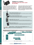
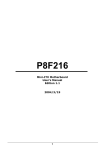
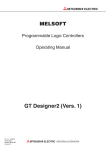
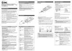
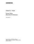
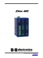
Zlinx 485
Manual Documentation Number: Zlinx485m-1808
www.bb-elec.com
www.bb-europe.com
Zlinx 485
Documentation Number: Zlinx485m-1808
This product was designed and manufactured in Ottawa, Illinois USA
Using domestic and imported parts by
International Headquarters
B&B Electronics Mfg. Co. Inc.
707 Dayton Road
Ottawa, IL 61350 USA
Phone (815) 433-5100 -- General Fax (815) 433-5105
Website: www.bb-elec.com
Sales e-mail: [email protected] -- Fax (815) 433-5109
Technical Support e-mail: [email protected] -- Fax (815) 433-5104
European Headquarters
B&B Electronics Ltd.
Westlink Commercial Park
Oranmore, Co. Galway, Ireland
Phone +353 91-792444 -- Fax +353 91-792445
Website: www.bb-europe.com
Sales e-mail: [email protected]
Technical Support e-mail: [email protected]
Revision – Original – April 2008
©2008 B&B Electronics Mfg Co Inc No part of this publication may be reproduced or transmitted in any
form or by any means, electronic or mechanical, including photography, recording, or any information
storage and retrieval system without written consent. Information in this manual is subject to change
without notice, and does not represent a commitment on the part B&B Electronics Mfg Co Inc.
B&B Electronics Mfg Co Inc shall not be liable for incidental or consequential damages resulting from the
furnishing, performance, or use of this manual.
All brand names used in this manual are the registered trademarks of their respective owners. The use of trademarks or other designations in this
publication is for reference purposes only and does not constitute an endorsement by the trademark holder.
Manual Documentation Number: Zlinx485m-1808
www.bb-elec.com
www.bb-europe.com
Introduction
Table of Contents
Chapter 1: Introduction................................................................................................ 2
About this Manual ...................................................................................................... 2
Support ....................................................................................................................... 2
Zlinx Product Family .................................................................................................. 2
Features ...................................................................................................................... 3
Package Checklist ...................................................................................................... 3
Chapter 2: Hardware .................................................................................................... 3
Zlinx 485 Modules ...................................................................................................... 3
Indicators, Connectors and Accessories ................................................................. 6
I/O Options and Characteristics .............................................................................. 11
Zlinx 485 Modes of Operation ................................................................................. 18
Connecting the Hardware ........................................................................................ 19
Chapter 3: Getting Started .......................................................................................... 21
Zlinx 485 Installation ................................................................................................ 21
Computer System Requirements ............................................................................ 21
Installing Zlinx 485 Software ................................................................................... 21
Connecting Zlinx 485 to a PC .................................................................................. 22
Starting Zlinx 485 Manager ...................................................................................... 22
Chapter 4: Configuration & Operation...................................................................... 26
Configuring Zlinx 485............................................................................................... 26
Peer-to-Peer Mode Settings .................................................................................... 28
Updating Zlinx 485 Firmware .................................................................................. 33
Chapter 5: Modbus Help ............................................................................................ 35
Modbus ASCII/RTU Basics ...................................................................................... 35
Hints and Tips .......................................................................................................... 36
Appendix A: Product Specifications ........................................................................ 37
Appendix B: Dimensional Diagrams......................................................................... 40
Appendix C: Serial Connections ............................................................................... 41
Appendix D: Modbus I/O Assignments .................................................................... 44
Appendix E: Zlinx 485 Models and Features ........................................................... 47
Appendix F: Zlinx 485 Troubleshooting .................................................................... 48
Appendix G: Terms and Definitions .......................................................................... 49
Manual Documentation Number: Zlinx485m-1808
www.bb-elec.com
www.bb-europe.com
Introduction
Chapter 1: Introduction
Thank you for purchasing a Zlinx 485 product! This product has been manufactured
to the highest standards of quality and performance to ensure your complete satisfaction.
About this Manual
This manual has been created to assist you in installing, configuring and using your Zlinx
485 Base module. Please read it carefully and follow the instructions to achieve best
results.
Support
For additional information on this and other B&B products, and for technical support, call
815.433.5100 option 3, or access the B&B Electronics website at www.bb-elec.com.
Zlinx Product Family
Zlinx 485 Base modules provide easy-to-use, cost-effective peer-to-peer or Modbus
solutions.
Figure 1. A Zlinx ZZ-NX485 Module
Manual Documentation Number: Zlinx485m-1808
www.bb-elec.com
www.bb-europe.com
Introduction
The Zlinx 485 family of products features a selection of operational modes,
communications modes, Modbus and I/O combinations. The system is scalable making it
easy to start with a few I/O points and build a system with the required I/O-Modbus mix.
Features
•
•
•
•
•
•
•
•
•
•
•
•
•
Choice of number and type of digital and analog I/O
Supports RS-232 and RS-422/485 lines
Sourcing or sinking digital outputs available
Configurable NPN (Sinking) and PNP (Sourcing) digital inputs
Flexible and scalable by adding expansion modules
MODBUS and Peer-to-Peer communications modes
Small, economical and configurable
Tolerates a wide operating temperature range
Choice of a range of DC power sources
Power, Data and Bus LED’s
Removable screw terminal blocks for power supply and I/O-Modbus connections
Zlinx 485 Manager configuration software
DIN rail mountable
Package Checklist
Zlinx 485 Base modules are shipped with the following items included:
9 Zlinx 485 Base module
9 A printed version of the Zlinx 485 Quick Start guide
9 CD-ROM disc with
-Zlinx 485 Manager configuration software
-Zlinx 485 Firmware Updater
-This manual in PDF format
-A quick start guide in PDF format
9 6 foot RJ45 male to serial (DB9 female) adapter cable
Expansion modules are shipped with the following items included:
9 Zlinx 485 Expansion module
9 A printed version of the Zlinx 485 Quick Start guide
Manual Documentation Number: Zlinx485m-1808
www.bb-elec.com
www.bb-europe.com
Hardware
Chapter 2: Hardware
Zlinx 485 encompasses a growing family of products including Modbus, Peer-to-Peer,
base modules, expansion modules, configuration software and accessories. All modules
are built into similar enclosures featuring male local bus plugs and female local bus
receptacles on the sides, which allow modules to connect together. Modules are DIN rail
mountable and feature removable screw terminal blocks.
Zlinx 485 Modules
Zlinx 485 systems consist of base modules and expansion modules. Expansion modules
are configured using a base module, which also has programming capabilities. The base
module is connected to a PC that is running the Zlinx 485 Manager software. Zlinx 485
systems can operate in Modbus or Peer-to-Peer modes. In Modbus mode a Zlinx 485
system exchanges Modbus messages with a Modbus capable base module. In Peer-topeer mode two Zlinx 485 systems are linked in a slave-master connection to provide
dependable, direct serial communications.
Figure 2. Front View of Zlinx 485 Base and Expansion Modules
Manual Documentation Number: Zlinx485m-1808
www.bb-elec.com
www.bb-europe.com
Hardware
Base Modules
Each Zlinx 485 system is built around a base module. Base modules provide Modbus,
digital and/or analog I/O and communicate with other Zlinx nodes.
Figure 3. A Typical Base Module
Several different combinations of digital inputs (DI), digital outputs (DO), analog inputs
(AI) and analog outputs (AO) are available. For example, the ZZ-NA-485 Base module
features a combination of two AI’s, two AO’s, two DI’s and two DO’s in a package.
Expansion Modules
Up to six expansion modules can be plugged into the base module to add more I/O
capabilities in any combination needed. For example, the ZZ-8DO-T Expansion module
provides eight additional digital outputs; the ZZ-2AI2AO provides two analog inputs and
two analog outputs.
Refer to Appendix E for a list of Zlinx 485 models and features.
Expansion modules connect to base modules by plugging the modules together, engaging
the local bus connectors located on the sides of the boxes. Male plugs on expansion
modules plug into female connectors on the side of the base module or other expansion
modules, resulting in a horizontal “stack” with the base module on the left and expansion
modules extending to the right.
Manual Documentation Number: Zlinx485m-1808
www.bb-elec.com
www.bb-europe.com
Hardware
Figure 4. Base and Expansion Modules Connected Together
Programming the Base Module using the RS232 connector
The base module has a programming feature that can be used to configure that base
module as well as expansion modules. The base module connects to the PC for
configuration. Connect a PC through the serial port (COM1 to 16) using the provided
RJ45 male to serial (DB9 female) cable.
Note: A standard RJ45 to serial (DB9) cable will not work, use only the one supplied
Figure 5. Connecting a PC and Base
Manual Documentation Number: Zlinx485m-1808
www.bb-elec.com
www.bb-europe.com
Hardware
Indicators, Connectors and Accessories
LED Indicators
Zlinx 485 Base modules have three LED indicators: a Power LED, a Data LED
Local Bus Data LED.
and a
Expansion modules have two LED’s: a Power LED and a Local Bus Data LED
Power LED
The Power LED illuminates (red) immediately on power up indicating that DC power is
present on the power supply terminals.
Data LED
The Data LED blinks (green) when data is being transmitted or received, either to an
expansion module or another base module. When the LED is off no data is being
transmitted or received.
Bus LED
The Bus LED blinks (green) when data is being transmitted or received on the local bus
connection. When the LED is off no data is being transmitted or received.
Note: If communications is not established within a preset number of retries (default is 10) the Data
and Bus LED’s blink alternately to indicate a loss of communications.
Connectors
Zlinx 485 Base and Expansion modules feature connectors for connecting field I/O
wiring and plugging together Zlinx 485 modules (local bus). In addition, Zlinx 485 Base
modules include connectors for connecting a power supply and an RJ45 connecter to
connect to the PC using the supplied RJ45 to serial cable.
Manual Documentation Number: Zlinx485m-1808
www.bb-elec.com
www.bb-europe.com
Hardware
Figure 6.
Power Supply Connector
The Power Supply connector (base modules only) is a two-position removable terminal
block located on the top of the unit. Terminal spacing is 3.5 mm. The terminal block
accepts solid and stranded wires from 28 AWG to 16 AWG. Please check polarity
marking in Figure 8.
Refer to the following section for information on Power Supply Requirements.
Expansion modules receive power from the base module via the local bus connector.
Local Bus Connectors
Local Bus connectors are included on all base and expansion modules. These connectors
are dual row, 14 pin (2 mm spacing) connectors. Base modules have only a female
connector. Expansion modules have male connectors on one side and female connectors
on the other. Modules are plugged together to supply power and facilitate communication
between modules.
When adding an Expansion module to a Base module the male connector on the expansion
module plugs into the female connector on the base module. The second expansion module plugs
into the first, and so on, up to a maximum of six expansion modules.
Manual Documentation Number: Zlinx485m-1808
www.bb-elec.com
www.bb-europe.com
Hardware
Figure 7. Local Bus Connector Location
RS-422/485 and I/O connectors for base and expansion modules are removable (plug in)
screw terminal blocks located on the front and top of the unit. Terminal spacing is 3.5
mm. Depending on the specific model, the number of terminals may vary. The maximum
is 16 terminals (two 8-terminal blocks) for I/O, with an additional 5 terminals for RS422/485 on the base module.
The Serial Port Connector on the Zlinx 485 is an RJ45 female connector (configured as
a DCE) device supporting RS-232 serial communications including TD (Pin 3 on the
DB9 end), RD (Pin 2) and GND (Pin 5) signal lines. If the Modbus device you are
connecting to the Zlinx Base Module is configured as a DTE device you will use a
straight-through serial cable. If the Modbus device is configured as a DCE device, use a
null modem cable or adapter.
Refer to Appendix C for connection pin-outs.
RS-422/485 Connector
The RS-422/485 connector on the Zlinx Base module is a five position removable
terminal block with screw downs. The connector provides screw connections for:
•
•
•
•
•
Terminal 1 – TDA(-)
Terminal 2 – TDB(+)
Terminal 3 – RDA(-)
Terminal 4 – RDB(+)
Terminal 5 – GND
Manual Documentation Number: Zlinx485m-1808
www.bb-elec.com
www.bb-europe.com
Hardware
Figure 8.
Zlinx 485 Base Module RS-422/485 Connector
RS-422/485 Four-Wire Mode
When the Zlinx Base module is configured to operate in RS-422/485 four-wire mode the
receive terminals are connected to the transmit terminals of the Modbus device it is
communicating with. Its transmit terminals are connected to the receive terminals of the
Modbus device it is communicating with.
Figure 9. RS-422/485 Four-Wire Connection
RS-422/485 Two-Wire Mode
When the Zlinx Base module is configured to operate in RS-485 two-wire mode (RS422/485 switch in the right position) the two-wire RS-485 two-wire communications
cable pair is connected to Terminals TDB and TDA. The communications cable
ground/shield is connected to GND.
Manual Documentation Number: Zlinx485m-1808
www.bb-elec.com
www.bb-europe.com
Hardware
Figure 10.
RS-485 Two-Wire Connection
No jumpers are required to bridge the transmit and receive lines in two-wire mode.
RS-232 Connection
Connect to RS-232 using the RJ45 jack on the front Base module, using the supplied
RJ45 male to serial (DB9 female) cable. Note: RTS is reserved for use by the
configuration software only. Asserting RTS during normal operation will result in a
communication failure. Disable RTS if your hardware supports it.
Note: A standard RJ45 to serial (DB9) cable will not work, use only the one supplied
Power Supply Requirements
Zlinx 485 systems can be powered from 10 to 30 VDC power sources. No supply is
included since the power rating of the supply will depend on the total power requirements
of all modules used in the system.
Appendix A contains a listing of power requirements for all Zlinx 485 modules.
Mounting Hardware
Zlinx 485 modules can be DIN rail mounted. The DIN mounting clip and spring is
included on each module.
Manual Documentation Number: Zlinx485m-1808
www.bb-elec.com
www.bb-europe.com
Hardware
Figure 11. DIN Clip with Spring on a Zlinx 485 Module
I/O Options and Characteristics
I/O Options
The Zlinx 485 family of products features a variety of input and output options. Base and
expansion module options include:
•
•
•
•
•
•
•
2 analog inputs, 2 analog outputs, 2 digital inputs and 2 digital outputs (sourcing or
sinking driver)
4 digital inputs and 4 digital outputs (sourcing or sinking driver)
8 digital inputs
8 digital outputs (sourcing or sinking driver)
o 8 relay output model available
4 analog inputs
o RTD Temperature input module available
4 analog outputs
2 analog inputs and 2 analog outputs
(Modules continue to be developed with additional features and options.)
Refer to Appendix E for a list of available models and options.
I/O Types and Characteristics
Digital Inputs
DI’s can detect the presence of contact closures, transistor switches or on/off DC voltage
signals (low or high logic levels). Voltages below 0.8 VDC are interpreted as a low state.
Voltages between 4.0 VDC and 48 VDC are interpreted as a high state.
DI’s are also programmable to be NPN or PNP
Manual Documentation Number: Zlinx485m-1808
www.bb-elec.com
www.bb-europe.com
Hardware
Digital Outputs
Digital outputs send on/off signals (low or high logic levels) to drive external devices
such as indicators, relay coils or the inputs of other equipment such as PLC’s, SCADA,
etc. Modules with digital outputs are available with sourcing or sinking drivers.
Sourcing (PNP transistor) drivers provide up to 240 mA per output at output voltages up
to 30 VDC to connected loads.
Sinking (NPN transistor) drivers can sink up to 40 mA per output at voltages up to 48
VDC.
Analog Inputs
Analog inputs accept voltage, current signals, or RTD temperature signals. When
configured as voltage inputs the full range is 0 to 10 VDC. When configured as current
inputs the full range is 0 to 20 mA and the input resistance is 240 ohms. When
configured as RTD input the allowable sensor types are PT100, PT1000 for CU10.
Analog Outputs
Analog outputs produce voltage or current output signals. When configured as voltage
outputs the full range is 0 to 10 VDC at 1 mA maximum. When configured as current
outputs the full range is 0 to 20 mA with a maximum load resistance of 375 Ω at 20 mA
and 10 VDC supply voltage.
0 to 20 mA AI’s and AO’s accommodate standard 4 to 20 mA instrumentation current loop signals.
I/O Wiring
DI Wiring
DI is programmable to be either NPN or PNP. The following diagram shows typical
connection wiring for various digital inputs:
Manual Documentation Number: Zlinx485m-1808
www.bb-elec.com
www.bb-europe.com
Hardware
Figure 12.
Typical Digital Input Wiring for Various Input Devices
(ZZ-4DID0-DCT Expansion Module)
Note: No external power supply wiring is required for Expansion modules
DO Wiring
The following diagram shows typical connection wiring for modules featuring sourcing
(PNP) drivers:
Figure 13.
Typical Digital Output Wiring for Sourcing Outputs
(ZZ-4DID0-DCT Expansion Module)
The following diagram shows typical connection wiring for modules featuring sinking
(NPN) drivers:
Manual Documentation Number: Zlinx485m-1808
www.bb-elec.com
www.bb-europe.com
Hardware
Figure 14.
Typical Digital Output Wiring for Sinking Outputs
(ZZ-4DID0-DCT1 Expansion Module)
AI Wiring
The following diagram shows typical connection wiring for analog inputs:
Figure 15.
Typical Analog Input Wiring (ZZ9D-NA-MR Base Module)
AO Wiring
The following diagram shows typical connection wiring for analog outputs:
Manual Documentation Number: Zlinx485m-1808
www.bb-elec.com
www.bb-europe.com
Hardware
Figure 16.
Typical Analog Output Wiring (ZZ9D-NA-MR Base Module)
RTD Wiring
The following diagram shows typical connection wiring for RTD inputs.
Figure 17.
Typical RTD Input Wiring
Manual Documentation Number: Zlinx485m-1808
www.bb-elec.com
www.bb-europe.com
Hardware
Figure 18.
Relay Wiring
The following diagram shows typical connection wiring for Relay outputs.
Figure 19.
Typical Relay Output Wiring
Modbus Mode Configuration
The Zlinx 485 Base module can be configured to operate in Modbus Mode. In Modbus mode
messages are sent across the physical layer (wiring configuration) from the Zlinx 485 base to the
Modbus network.
To use Modbus mode successfully, an understanding of the Zlinx 485 memory map
assignments is necessary.
Modbus function codes supported:
Function 1: Read DO Status
Function 2: Read DI’s
Function 3: Read AO Status
Function 4: Read AI’s
Function 5: Write Single DO’s
Function 6: Write to Single AO
Function 15: Write to Multiple DO’s
Messages sent between Zlinx 485 and a Modbus node use Modbus memory addresses to
specify what type of information is being sent and where it is stored. In the Modbus
addressing scheme each type of I/O (DO, DI, AI and AO) is stored in a different section
of the memory.
Manual Documentation Number: Zlinx485m-1808
www.bb-elec.com
www.bb-europe.com
Hardware
I/O Type
DO
DI
AI
AO
Figure 20.
Modbus Memory
Address
00001 to 00112
10001 to 10112
30001 to 30112
40001 to 40112
I/O Memory Areas Table
Within these sections, addresses are reserved for all Zlinx 485 modules that may be used.
Module
Base
Expansion 1
Expansion 2
Expansion 3
Expansion 4
Expansion 5
Expansion 6
Figure 21.
Memory Range
x0001 to x0016
x0017 to x0032
x0033 to x0048
x0049 to x0064
x0065 to x0080
x0081 to x0096
x0097 to x0112
Module I/O Addressing Table
The following examples show how the addressing works:
Example 1: To turn on the second digital output (DO2) on the Base Module, the Modbus
Base Module sends a message placing a logic 1 in memory location 00002.
Example 2: To cause expansion module 3 to output a specified voltage on AO1, the
Modbus Base Module sends a message to set the register at Modbus address 40049 to the
appropriate value.
A list of all Modbus address assignments for all Zlinx 485 points is shown in Appendix
D. Several important points about this list should be noted:
•
•
•
•
•
•
Some addresses are listed but not implemented in current versions of Zlinx 485
hardware.
Some addresses are reserved for internal Zlinx 485 use.
Some addresses are reserved for future use.
40000 series addresses store Analog Output data AND Frequency Counter data when
Digital Inputs are configured for Frequency Counter operation. For each module, the
first eight memory locations are assigned to AO data and the next four locations are
assigned to Frequency Counter data.
If a Modbus device communicating with Zlinx 485 tries to send to or receive from a
memory address not implemented by the hardware in use, the Zlinx 485 replies with
an exception response.
Users cannot span across two memory maps, i.e. from 34 to 50.
Manual Documentation Number: Zlinx485m-1808
www.bb-elec.com
www.bb-europe.com
Hardware
•
A maximum of 16 points can be displayed at any one time.
Appendix D of this manual contains a list of Modbus I/O assignments for the Zlinx 485.
Zlinx 485 Modes of Operation
Zlinx 485 systems can operate in Peer-to-Peer or Modbus modes.
Peer-to-Peer Mode
In Peer-to-Peer mode two Zlinx 485 systems provide full serial I/O functionality. In this
mode one Base is configured as the master and the other as the slave. (It does not matter
which end of the link is the master and which is the slave.) Both Base Modules must be
the same model. Analog and digital input signals connected to AI’s and DI’s on one
module appear on the corresponding AO’s and DO’s on the other module. Any
Expansion modules included in a Peer-to-Peer system must be chosen to be
complimentary. For example, if expansion module 1 on one end of the link is a ZZ-4AI
(4 analog inputs), expansion module 1 on the other end of the link must be a ZZ-4AO (4
analog outputs.
Figure 22.
Peer to Peer Mode
Modbus Mode
In Modbus mode standard Modbus messages can be sent and received between a Modbus
Base Module and a Zlinx 485 system. Data written to output addresses in the Zlinx 485
results in signals appearing on its outputs. Signals connected to Zlinx 485 inputs are
converted and stored in Modbus input memory locations and then sent across the link as
Modbus messages to the Modbus Base Module.
Manual Documentation Number: Zlinx485m-1808
www.bb-elec.com
www.bb-europe.com
Hardware
Figure 23.
Modbus Mode devices may be PLCs, RTUs, DCSs, or other Modbus devices,
with links up to 32 nodes per Modbus network
Connecting the Hardware
With an RS-232 connection, the Zlinx 485 Base module is connected to a Modbus
device via a DB-9M connector and an RS-232 cable. If the connected Modbus device is
configured as a DTE device, use a straight-through cable. If the connected Modbus
device is configured as a DCE device, use a null modem cable.
Always check the interface specifications of the Modbus device to determine whether it is a DTE or
DCE before connecting.
RS-232 may be connected to a PC using an RS-485 Converter, to allow using Modscan 32 to poll
the registers.
For RS-422/485 wiring, the Zlinx 485 Base module is connected to the Modbus device
via the RS-422/485 terminal block. In RS-422/485 four-wire mode a cable containing
two pairs and a ground/shield is used. In RS-485 two-wire mode a cable containing one
pair and a ground/shield is used.
Power is supplied to the converter via the power supply terminal block.
Manual Documentation Number: Zlinx485m-1808
www.bb-elec.com
www.bb-europe.com
Hardware
Figure 24. Zlinx Base Module 2 wire RS-485 Connections
Figure 25. Zlinx Base Module 4 wire RS-232 Connections
Manual Documentation Number: Zlinx485m-1808
www.bb-elec.com
www.bb-europe.com
Modbus Basics
Chapter 3: Getting Started
Zlinx 485 Installation
Zlinx 485 Mounting
Zlinx 485 modules are DIN rail mountable. Additional ZZ-DIN1 mounting kits can be
purchased for replacement. Each kit includes a DIN clip and spring and four spare screws
for the Zlinx 485 enclosure.
Computer System Requirements
The Zlinx 485 Manager software requires the following computer hardware and
operating systems:
•
•
A PC with one serial port available between COM1 and COM16
Windows XP (Home or Professional with SP1 and SP2), Windows 2000 (with SP4),
Windows 98 (SP1, Second Edition) or Windows ME
Installing Zlinx 485 Software
To install the Zlinx 485 Manager software:
1. Insert the CD included with your Zlinx 485 product into the CD ROM drive of your
PC.
2. The installation should launch automatically. If not:
a. Click Start on the Task Bar and select Run
b. Type in [CD drive letter]:\setup.exe
3. Follow the prompts to install the software.
When installation is complete Zlinx 485 Manager, Zlinx 485 Firmware Updater, and
.PDF files containing this manual and the Quick Start guide are accessible from the
Windows Start menu.
Manual Documentation Number: Zlinx485m-1808
www.bb-elec.com
www.bb-europe.com
Modbus Basics
Connecting Zlinx 485 to a PC
1. With power disconnected, connect the Base Module into the PC. [Shall change this
diagram]
Figure 26.
Connecting a PC and Base Module
2. Connect any required expansion modules to the base module. (The male local bus
connector on the first expansion module plugs into the female connector on the base
module. The second expansion module plugs into the first, etc.)
3. Connect the PC serial port to the Base Module using the supplied RJ45 male to serial
(DB9 female) 6 ft cable.
4. Re-apply power to the Zlinx 485 Base Module. The Power LED should light up.
Starting Zlinx 485 Manager
1. From the Windows Start menu, start the Zlinx 485 Manager software.
The Zlinx 485 splash window appears briefly, followed by the discovery window.
2. The Connection drop down list defaults to Automatic discovery. The software scans
through COM ports looking for Zlinx 485 devices. The scan starts with the most
recently used serial port in which a device was found.
Manual Documentation Number: Zlinx485m-1808
www.bb-elec.com
www.bb-europe.com
Modbus Basics
Figure 27.
Discovery Window
During the scan the Progress box displays information about the scanning process. If
a device is not found at the most recently successful port it continues to scan through
COM ports 1 to 16. The bar graph near the bottom of the window indicates progress.
3. If the device is not found the Progress box displays:
The device was not found on any serial port.
a. Check the power supply and serial cable connections
b. Click the Connect button. The connection process will be repeated and the device
should be found.
4. If Automatic connection is not desired, a particular COM port (1 to 16) can be
specified:
a. Select the COM port number from the Connection drop down list.
b. Click the Connect button to initiate the connection process.
Clicking the Stop button stops the module discovery process.
5. If the device is found, the Zlinx 485 Manager window opens.
Manual Documentation Number: Zlinx485m-1808
www.bb-elec.com
www.bb-europe.com
Modbus Basics
Figure 28.
Zlinx 485 Manager
The Zlinx 485 Manager window contains:
•
File and Help menus
•
Three tabbed panes: Information, Configuration, and Input/Output
•
A Help sidebar containing information and hints related to the current tab
•
A graphic display of the base and expansion Modules discovered
•
A Status bar (at the bottom) showing the COM port and communications
parameters (baud rate, parity, data bits, stop bits and flow control)
•
An Update button used to save configuration parameters to the modules.
•
An Exit button.
Information Tab
The Information tab displays a tree structure listing:
•
Base and expansion modules detected and their model numbers
•
Firmware version number for each module
Manual Documentation Number: Zlinx485m-1808
www.bb-elec.com
www.bb-europe.com
Modbus Basics
•
Hardware version number for each module
Configuration Tab
The Configuration tab contains fields that allow configuration of:
•
Communications Modes: Peer-to-Peer Master, Peer-to-Peer Slave, Modbus (and
related parameters)
Input/Output Tab
The Input/Output tab contains:
•
A tree structure listing input and output types for each module
•
Input and output configuration options
Manual Documentation Number: Zlinx485m-1808
www.bb-elec.com
www.bb-europe.com
Modbus Basics
Chapter 4: Configuration & Operation
Zlinx 485 Manager software is used to configure Zlinx 485 hardware. Using Zlinx 485
Manager, the system can be configured to operate in Peer-to-Peer or Modbus modes
(receiving Modbus commands and data from a Modbus base module). Digital inputs can
be configured to operate in Discrete (on/off) or Frequency Counter modes and analog
inputs and outputs are configurable for voltage or current loop operation.
Configuring Zlinx 485
Zlinx 485 modules can be configured to operate as Modbus nodes or as serial links in
Peer-to-Peer mode.
Configuring Modbus Mode
When the Zlinx 485 receives a Modbus message to write to a discrete output (0xxxx
addresses in its memory map), the Zlinx 485 module turns on its corresponding digital
output. If a message containing holding register data is received (4xxxx addresses in its
memory map), the Zlinx 485 module converts the value to a voltage or current signal on
the corresponding analog output.
Figure 29.
Modbus Mode devices may be PLCs, RTUs, DCSs, or other Modbus devices,
with links up to 32 nodes per Modbus network
Figure 30.
Digital and analog signals applied to the Zlinx 485 Expansion module’s input terminals
are converted to Modbus messages to be sent back to the base module. Digital inputs are
Manual Documentation Number: Zlinx485m-1808
www.bb-elec.com
www.bb-europe.com
Modbus Basics
stored as 1xxxx (coil) addresses; analog inputs are converted to 12 bit binary values and
stored in 3xxxx (input register) addresses.
To configure the Zlinx 485 for Modbus mode:
1. Select the Configuration tab.
2. Select the Modbus option button.
3. In the Modbus Address box, type the Modbus address to be used. Modbus address 0
is reserved for master systems that do not support broadcasts.
The allowable range of Modbus addresses is from 1 to 247. The default Modbus
address is 1.
Figure 31.
Configuration Tab with Default Values
Testing Modbus Mode Operation
Using a Modbus base module, a PC and Modbus simulation software (e.g. Modscan) you
can test the link and hardware, and investigate the operation of the Zlinx 485. Modscan is
a Windows application that simulates a Modbus master node. You can read from and
write to memory locations on the Zlinx 485. Modscan is available as a fully functional
time-limited demo from www.win-tech.com., and more information on the basics of
Modbus is available at www.bb-elec.com.
Manual Documentation Number: Zlinx485m-1808
www.bb-elec.com
www.bb-europe.com
Modbus Basics
Peer-to-Peer Mode Settings
In Peer-to-Peer mode digital and analog signals can be transferred in both directions
across a Zlinx 485 link. For successful communication both base modules must be the
same model and all expansion modules must be complimentary (e.g. DI to DO, AI to
AO) and arranged in the same order on the Local Bus. One is configured as Peer-to-Peer
Master and other is configured as Peer-to-Peer slave. It does not matter which one is
configured as master. Additionally, Peer-to-Peer Master address MUST match the Peerto-Peer Slave address (1-255).
Peer-to-Peer Master
To configure the Zlinx 485 Base module for Peer-to-Peer Master mode:
1. Select the Configuration tab.
2. Select the Peer-to-Peer Master option button.
Figure 32.
Peer-to-Peer Master Configuration
3. Set the Peer-to-Peer Master address from 1 to 255. Please note the Peer-to-Peer Slave
address must also match.
4. The Polling Rate box contains the number of seconds between polls by the master.
The default value of 1 second is usually satisfactory. The range of values is 0 to 20
seconds. If the I/O points are not updating properly, try increasing the value.
5. The Retry Count box contains the number of attempts that will be made to
communicate with the slave device before the module indicates communication has
Manual Documentation Number: Zlinx485m-1808
www.bb-elec.com
www.bb-europe.com
Modbus Basics
been lost. Lost communication is indicated by the Bus LED’s blinking alternately.
The default value of 10 is usually satisfactory. The range of values is 10 to 255.
Peer-to-Peer Slave
To configure the Zlinx 485 Base Module for Peer-to-Peer Slave Mode:
1. Select the Configuration tab.
2. Select the Peer-to-Peer Slave option button...
3. Set the Peer-to-Peer Slave address from 1 to 255. Please note the Peer-to-Peer Master
address must also match.
Figure 33.
Peer-to-Peer Slave Configuration
Input/Output Settings
Digital inputs and analog inputs/outputs on Zlinx 485 modules are configured from the
Input/Output tab of the Zlinx 485 Manager. The first two digital inputs on any module
can be configured as Discrete inputs or Frequency Counter inputs. (Any additional digital
inputs operate as Discrete inputs only.) Frequency Counter operation is only functional
when the Zlinx 485 is set up in Modbus mode. Analog inputs and outputs can be
configured for voltage or current loop operation.
To configure digital and analog I/O:
1. Select the Input/Output tab.
Manual Documentation Number: Zlinx485m-1808
www.bb-elec.com
www.bb-europe.com
Modbus Basics
An input tree appears listing all base and expansion modules in the system and the
inputs available on them.
Figure 34.
Digital Input Configuration
2. Select the Digital Input to be configured.
3. Select Discrete or Frequency Counter (for the first two inputs only). Do NOT exceed
5 kHz for frequency input.
Setting the Digital Mode of either of the first two DI’s to Frequency Mode sets both DI’s on that
module to the same mode. Do NOT exceed 5 kHz for frequency input.
4. Select the Analog Input to be configured.
5. Select the required Analog Mode (0 to 10 VDC or 0 to 20 mA).
Setting the Analog Mode of one AI or AO sets all AI’s and AO’s on that module to the same mode.
Manual Documentation Number: Zlinx485m-1808
www.bb-elec.com
www.bb-europe.com
Modbus Basics
Figure 35.
Analog Input Configuration
6. Select the Analog Output to be configured.
7. Select the required Analog Mode (0 to 10 VDC or 0 to 20 mA).
If RTD module present then,
1. Select the Input/Output tab.
Manual Documentation Number: Zlinx485m-1808
www.bb-elec.com
www.bb-europe.com
Modbus Basics
An input tree appears listing all base and expansion modules in the system and the inputs
available on them.
2. Select the RTD to be configured.
3. To increase speed, RTD channels may be turned on or off. If nothing is connected to
the RTD channel, then uncheck the Channel Enabled option.
4. Select the RTD type as PT100, PT1000, CU10 depending on your RTD type.
5. Select if you have wired a 2, 3, or 4 wire RTD probe to the input module.
Setting the Analog Mode of one AI or AO sets all AI’s and AO’s on that module to the same mode.
Saving the Configuration
When all configuration settings are complete, click the Update button to save them in the
Zlinx 485 Base and Expansion modules.
1. The Progress bar at the bottom of the windows shows the progress of the update.
2. The Status bar displays the following text:
Manual Documentation Number: Zlinx485m-1808
www.bb-elec.com
www.bb-europe.com
Modbus Basics
Sending module parameters to the base module.
3. When the updating process is complete, the Status bar displays the message:
The configuration has been sent successfully.
Updating Zlinx 485 Firmware
From time to time updated firmware may become available for Zlinx 485 modules (from
the B&B Electronics website). When the Zlinx 485 Manager software is installed on your
computer the Zlinx 485 Updater software is also installed. This can be used to update the
firmware in your Zlinx 485 modules. The following procedure describes the firmware
updating process
4. Disconnect power from the base module.
5. Disconnect all modules from external equipment. (The easiest way to disconnect is to
unplug all terminal blocks.)
6. Connect expansion modules requiring updates to the base module. (The male local
bus connector on the first expansion module plugs into the female connector on the
base module. The second expansion module plugs into the first, etc.)
7. Connect the PC serial port (COM 1 to 16) to the base module using the supplied RJ45
(male) to serial (DB9 female) cable.
8. From the Windows Start menu, start the Zlinx 485 Firmware Updater software.
9. The Zlinx 485 Firmware Updater Caution dialog box appears:
Figure 36.
Firmware Updater Caution Dialog Box
10. Select the COM port from the Connection drop down list.
Manual Documentation Number: Zlinx485m-1808
www.bb-elec.com
www.bb-europe.com
Modbus Basics
11. Click Connect.
12. Re-apply power to the Zlinx 485 Base module. The Power LED should light up.
13. The Zlinx 485 Firmware Updater window opens and displays a list of the base and
expansion modules.
14. On the module list, select the base or expansion module to be updated.
15. In the Firmware Image drop down box, select the image file (.hex).
16. Click the Program button to load the firmware into the module.
17. When all updates are complete, click Exit.
18. Before reconnecting the I/O run the Zlinx 485 Manager software and check to ensure
all modules are configured properly.
19. When the configuration check is complete:
a. Exit the Zlinx 485 Manager program
b. Disconnect power from the Base Module
c. Reconnect the I/O.
20. Re-connect power to the Base Module.
Manual Documentation Number: Zlinx485m-1808
www.bb-elec.com
www.bb-europe.com
Modbus Basics
Chapter 5: Modbus Help
Modbus ASCII/RTU Basics
The Modbus protocol emerged in the mid-1970s as an early protocol for linking terminals
with Modicon PLCs using a master/slave (sometimes called a master/client) relationship.
A simple, open, message-based protocol, it caught on quickly and became a defacto
standard in the industry. It supports asynchronous point-to-point and multidrop
communications and can be used with a variety of serial interfaces (RS-232, RS-422, RS485, modems, etc).
The original Modbus specification included two possible transmission modes: ASCII and
RTU. Modbus RTU mode is the most common implementation, using binary coding and
CRC error-checking. Modbus ASCII messages, though somewhat more readable because
they use ASCII characters, is less efficient and uses less effective LRC error checking.
ASCII mode uses ASCII characters to begin and end messages whereas RTU uses time
gaps (3.5 character times) of silence for framing. The two modes are incompatible so a
device configured for ASCII mode cannot communicate with one using RTU.
All Modbus communications are initiated by Modbus masters using a polling
query/response format. The master can send broadcast messages (using a slave address of
0), which all slaves accept, but do not reply to. More commonly the master polls
individual slaves sequentially. In each poll it sends a message containing a device
address, followed by a function code, any data that maybe required, and an error check
field. The addressed slave responds with a similar message structure. Typically it repeats
back its address and the function code, and then sends a field indicating the number of
bytes of data it is sending, followed by the data and the error check field.
Slave addresses can range from 1 to 247. Function codes include several common ones
typically used in all applications, and additional ones that may be implemented in specific
cases. Common function codes include: Read Coil Status (01), Read Input Status (02),
Read Holding Registers (03) and Read Input Registers (04).
When a master sends a message to a slave it expects to receive a valid response within
certain length of time. If the slave does not receive the message, or if the slave receives
the message but an error is detected, it does not respond. If the slave cannot respond
appropriately for some other reason (e.g. it does not recognize the function code), it will
return a message containing an exception response.
Manual Documentation Number: Zlinx485m-1808
www.bb-elec.com
www.bb-europe.com
Modbus Basics
Hints and Tips
A few simple suggestions that may assist you if your system is experiencing problems
include:
•
•
•
Slowing down the polling rate may be helpful if power cycling doesn’t cure the
problem.
A common misperception is that every serial network must terminate with a resistor.
While this was true of early serial network configurations, it’s typically the wrong
answer – call our technical support and verify if you’re an exception, at 815.433.5100
option 3.
A sometimes difficult problem is difference in grounding voltage between various
network locations. Stray voltage from lightning or other sources may also find its way
onto the network. These conditions make isolation necessary in many settings.
Manual Documentation Number: Zlinx485m-1808
www.bb-elec.com
www.bb-europe.com
Product Specifications
Appendix A: Product Specifications
Base Module Models:
Expansion Module Models:
Quick Start guide:
Manual:
CD-ROM disc:
Operating Systems supported:
Dimensions:
Expansion Feature:
Power Indicator:
ZZ-NA-485, ZZ-NB-485, ZZ-NC-485, ZZ-ND-485
ZZ-4AI, ZZ-4AO, ZZ-2AI2AO, ZZ-8D0-T, ZZ-8D0-T1, ZZ8DDO-R, ZZ-4DI4DO-DCT, ZZ4DI4DO-DCT1, ZZ4RTD1
Paper copy, PDF available on enclosed CD-ROM disc
Available on enclosed CD-ROM disc, and on B&B website
Zlinx 485 Manager
PDF of Zlinx 485 User Manual
PDF of Quick Start guide
Windows ME/98/2000/XP
1.15 x 3.65 x 5 in (2.92 x 9.27x 12.7 cm)
1 base module and up to 6 expansion modules
Red LED
Data Indicator:
Green LED (blinks with TD or RD data traffic, Off = no data traffic)
Bus Indicator:
Green LED (blinks with TD or RD bus traffic, Off = no bus traffic)
Data Error Indicator:
Data & Bus LED’s blink alternately
Modbus Connectors:
Removable screw terminal (5 position) block, 3.5 mm spacing
Serial Connectors
Side connector:
RF-45 female, RS-232
Top connector:
Removable screw terminal block (5) with screw down clamping
Interface Lines Supported:
Serial Data Rates:
I/O Connectors:
RS-232
RS-422/485 RDB+, RDA-, TDB+, TDA1200, 2400, 3600, 4800, 9600, 19200, 38400, 57600, 115200, 230400 bps
Removable screw terminal (2, 4 or 8 position) block, 3.5 mm spacing
Digital Inputs
Voltage Range:
0 to 48 VDC
Low Voltage (0):
0.8 V maximum
High Voltage (1):
4.0 V minimum
Pull up Resistor (NPN Input):
Pull down Resistor (PNP Input)
130K
10K
Manual Documentation Number: Zlinx485m-1808
www.bb-elec.com
www.bb-europe.com
Product Specifications
Frequency Input:
Two DI inputs per module software selectable as Frequency Counters, 0 to 5 kHz range
(do NOT exceed more than 5kHz)
Digital Outputs
Voltage Range:
Open Source:
10 to 45 VDC (for sourcing outputs), 0 toVDC (for sinking outputs)
40 mA per output
Analog Inputs/Outputs
Ranges:
Resolution:
0 to 10 VDC or 0 to 20 mA
12 bit
Input Accuracy:
0.15 % full scale reading typical, 0.2 % max
Output Accuracy:
0.15 % full scale reading typical, 0.2 % max
AI Load Resistance:
AO Max Output Current:
AO Max Source Load:
Input Protection:
Power Supply Voltage
Requirements:
Power Supply:
Base Module Power Connector:
100 Mega ohms when configured for voltage input
250 ohms when configured for current input
1 mA when configured for voltage output
375 ohms at 20 mA and 10V input voltage when configured for current output
Over-voltage to 2x max input voltage
10 VDC to 30 VDC
Not included
Removable screw terminal (2) block, 3.5 mm spacing
Relay Outputs
Number of Relays:
Type:
Output Connection:
Common Connectin:
Ratings:
8
C (normally open and normally closed)
3.5mm removable terminal block (2 per output)
3.5mm removable terminal block (1 per bank of 4 output)
250 VAC @ 8A, 30 VDC @ 5A (maximum per bank of 4 as grouped on the label)
RTD Inputs
Number of RTD:
Wire configuration:
Type:
Input Connection:
Temperature Range:
4
2, 3, and 4 wire
PT100*, PT1000*, Cu10**
*Optimized for temperature coefficient of 385
**Optimized for temperature coefficient of 427
3.5mm removable terminal block (4 per output)
PT100 = -200 to 650 º C
PT1000 = -200 to 100 º C
Cu10 = -100 to 260 º C
Manual Documentation Number: Zlinx485m-1808
www.bb-elec.com
www.bb-europe.com
Product Specifications
Resolution:
Accuracy @ 25ºC:
0.1 º C across -40 to 85 º C
±0.5ºC typical
Accuracy -40 to 85ºC:
±2.0ºC maximum
Power Consumption:
ZZ-Nx-485 = 1W
ZZ-4AI = 1W
ZZ-4AO = 1.1W
ZZ-2AI2AO = 1.2W
ZZ-8DI-DC = 0.4W
ZZ-8DO-T = 15.8W
ZZ-8DO-T1 = 1.1W
ZZ-8DO-R = 3.2W
ZZ-4DI4DO-DCT = 8.1W
ZZ-4DI4DO-DCT1 = 1.0W
ZZ-4RTD1 = 0.4W
Operating Temperature:
Storage Temperature:
-40 to 80°C (-40 to 176 °F)
ZZ-8DO-R -40 to 65ºC (-40 to 149 º F)
-40 to 85 °C (-40 to 185 °F)
Humidity:
10% to 90% R.H. non-condensing
Enclosure Rating:
IP30
Mounting:
Certifications:
Accessories and Replacement
Parts:
DIN rail mount, 35 mm
FCC: Part 15 Class A
CISPR (EN55022) Class A
EN61000-6-1 Generic Standards for Residential, Commercial & Light Industrial
EN61000-4-2 ESD
EN61000-4-3 RFI
EN61000-4-4 EFT
EN61000-4-6 CI
ZZ-DIN1
ZZ-TB1
DIN clip and spring for all ZZ products, 4 spare screws for enclosure
Removable terminal block for all ZZ modules
Manual Documentation Number: Zlinx485m-1808
www.bb-elec.com
www.bb-europe.com
Dimensional Diagrams
Appendix B: Dimensional Diagrams
Figure 37.
Dimensional Diagram of a Zlinx 485 Base Module
Manual Documentation Number: Zlinx485m-1808
www.bb-elec.com
www.bb-europe.com
Serial Connections
Appendix C: Serial Connections
RS-232 Pinouts
RJ-45F
Pin
1
2
3
4
5
6
7
8
Signal
RS-232
DCE
Signal Ground
Signal Ground
Receive Data
Transmit Data
Clear to Send
Request to Send
Not Used
Not used
GND
GND
RD
TD
CTS
RTS
-----
----IN
OUT
IN
OUT
-----
Figure 38. RS-232 Connections for RJ45 type plug
Note: PIN 4 (RTS) is reserved for the configuration software only. Asserting RTS during normal operation will result in a
communication failure. Disable RTS if your hardware supports it
RJ45 Male to RS-232 Female Pinout
Manual Documentation Number: Zlinx485m-1808
www.bb-elec.com
www.bb-europe.com
Serial Connections
RJ45 male
1
2
3
4
5
6
7
8
DB9 female
5
5
3
2
7
8
9
9
Signal Name
Signal Ground
Signal Ground
Receive Data
Transmit Data
Clear to Send
Request to Send
Not Used
Not used
Direction
----IN
OUT
IN
OUT
-----
Figure 39. RJ45 Male to RS232 female adapter cable
RS-422/485 4 Wire Pinouts
Signal Name
Transmit Data (-)
Transmit Data (+)
Receive Data (-)
Receive Data (+)
Signal Ground (COM)
Figure 40.
Label
TDA(-)
TDB(+)
RDA(-)
RDB(+)
COM
Direction
Out
Out
In
In
---
Terminal
1
2
3
4
5
Zlinx Base Module Terminal Block Pin-out for RS-422/485 Four-Wire Operation
Note: 4-Wire Connections must be wired as Mater/Slave. Refer to B&B Electronics RS-485
Application Note.
RS-485 2 Wire Pinouts
Manual Documentation Number: Zlinx485m-1808
www.bb-elec.com
www.bb-europe.com
Serial Connections
Signal Name
DataA (-)
DataB (+)
Not used
Not used
Signal Ground (COM)
Figure 41.
Label
TDA(-)
TDB(+)
RDA(-)
RDB(+)
COM
Direction
In/Out
In/Out
-------
Terminal
1
2
3
4
5
Zlinx 485 Base Module Terminal Block Pin-out for RS-485 Two-Wire Operation
Manual Documentation Number: Zlinx485m-1808
www.bb-elec.com
www.bb-europe.com
Modbus I/O Assignments
Appendix D: Modbus I/O Assignments
00001-00112 Discrete Digital Outputs
Modbus function codes supported are:
Function 1: Read DO Status
Function 2: Read DI’s
Function 3: Read AO Status
Function 4: Read AI’s
Function 5: Write to Single DO (firmware v2.0 or higher)
Function 6: Write to Single AO
Function 15: Write to Multi DO’s
Modbus Address
00001
00002
00003
00004
00005
00006
00007
00008
00009
00010
00011
00012
00013
00014
00015
00016
00017
00018
00019
00020
00021
00022
00023
00024
00025
00026
00027
00028
00029
00030
00031
00032
00033
00034
00035
00036
Description
Base Digital Output-1
Base Digital Output-2
Base Digital Output-3
Base Digital Output-4
Base Digital Output-5
Base Digital Output-6
Base Digital Output-7
Base Digital Output-8
Base Digital Output-9
Base Digital Output-10
Base Digital Output-11
Base Digital Output-12
Base Digital Output-13
Base Digital Output-14
Base Digital Output-15
Base Digital Output-16
EXP-1 Digital Output-1
EXP-1 Digital Output-2
EXP-1 Digital Output-3
EXP-1 Digital Output-4
EXP-1 Digital Output-5
EXP-1 Digital Output-6
EXP-1 Digital Output-7
EXP-1 Digital Output-8
EXP-1 Digital Output-9
EXP-1 Digital Output-10
EXP-1 Digital Output-11
EXP-1 Digital Output-12
EXP-1 Digital Output-13
EXP-1 Digital Output-14
EXP-1 Digital Output-15
EXP-1 Digital Output-16
EXP-2 Digital Output-1
EXP-2 Digital Output-2
EXP-2 Digital Output-3
EXP-2 Digital Output-4
#Bytes
-
Count
0-1
0-1
0-1
0-1
0-1
0-1
0-1
0-1
0-1
0-1
0-1
0-1
0-1
0-1
0-1
0-1
0-1
0-1
0-1
0-1
0-1
0-1
0-1
0-1
0-1
0-1
0-1
0-1
0-1
0-1
0-1
0-1
0-1
0-1
0-1
0-1
V Range
Refer to Appendix A
Refer to Appendix A
Refer to Appendix A
Refer to Appendix A
Refer to Appendix A
Refer to Appendix A
Refer to Appendix A
Refer to Appendix A
Refer to Appendix A
Refer to Appendix A
Refer to Appendix A
Refer to Appendix A
Refer to Appendix A
Refer to Appendix A
Refer to Appendix A
Refer to Appendix A
Refer to Appendix A
Refer to Appendix A
Refer to Appendix A
Refer to Appendix A
Refer to Appendix A
Refer to Appendix A
Refer to Appendix A
Refer to Appendix A
Refer to Appendix A
Refer to Appendix A
Refer to Appendix A
Refer to Appendix A
Refer to Appendix A
Refer to Appendix A
Refer to Appendix A
Refer to Appendix A
Refer to Appendix A
Refer to Appendix A
Refer to Appendix A
Refer to Appendix A
Manual Documentation Number: Zlinx485m-1808
www.bb-elec.com
www.bb-europe.com
Modbus I/O Assignments
Modbus Address
00037
00038
00039
00040
00041
00042
00043
00044
00045
00046
00047
00048
00049
00050
00051
00052
00053
00054
00055
00056
00057
00058
00059
00060
00061
00062
00063
00064
00065
00066
00067
00068
00069
00070
00071
00072
00073
00074
00075
00076
00077
00078
00079
00080
00081
00082
00083
00084
00085
Description
EXP-2 Digital Output-5
EXP-2 Digital Output-6
EXP-2 Digital Output-7
EXP-2 Digital Output-8
EXP-2 Digital Output-9
EXP-2 Digital Output-10
EXP-2 Digital Output-11
EXP-2 Digital Output-12
EXP-2 Digital Output-13
EXP-2 Digital Output-14
EXP-2 Digital Output-15
EXP-2 Digital Output-16
EXP-3 Digital Output-1
EXP-3 Digital Output-2
EXP-3 Digital Output-3
EXP-3 Digital Output-4
EXP-3 Digital Output-5
EXP-3 Digital Output-6
EXP-3 Digital Output-7
EXP-3 Digital Output-8
EXP-3 Digital Output-9
EXP-3 Digital Output-10
EXP-3 Digital Output-11
EXP-3 Digital Output-12
EXP-3 Digital Output-13
EXP-3 Digital Output-14
EXP-3 Digital Output-15
EXP-3 Digital Output-16
EXP-4 Digital Output-1
EXP-4 Digital Output-2
EXP-4 Digital Output-3
EXP-4 Digital Output-4
EXP-4 Digital Output-5
EXP-4 Digital Output-6
EXP-4 Digital Output-7
EXP-4 Digital Output-8
EXP-4 Digital Output-9
EXP-4 Digital Output-10
EXP-4 Digital Output-11
EXP-4 Digital Output-12
EXP-4 Digital Output-13
EXP-4 Digital Output-14
EXP-4 Digital Output-15
EXP-4 Digital Output-16
EXP-5 Digital Output-1
EXP-5 Digital Output-2
EXP-5 Digital Output-3
EXP-5 Digital Output-4
EXP-5 Digital Output-5
#Bytes
-
Count
0-1
0-1
0-1
0-1
0-1
0-1
0-1
0-1
0-1
0-1
0-1
0-1
0-1
0-1
0-1
0-1
0-1
0-1
0-1
0-1
0-1
0-1
0-1
0-1
0-1
0-1
0-1
0-1
0-1
0-1
0-1
0-1
0-1
0-1
0-1
0-1
0-1
0-1
0-1
0-1
0-1
0-1
0-1
0-1
0-1
0-1
0-1
0-1
0-1
V Range
Refer to Appendix A
Refer to Appendix A
Refer to Appendix A
Refer to Appendix A
Refer to Appendix A
Refer to Appendix A
Refer to Appendix A
Refer to Appendix A
Refer to Appendix A
Refer to Appendix A
Refer to Appendix A
Refer to Appendix A
Refer to Appendix A
Refer to Appendix A
Refer to Appendix A
Refer to Appendix A
Refer to Appendix A
Refer to Appendix A
Refer to Appendix A
Refer to Appendix A
Refer to Appendix A
Refer to Appendix A
Refer to Appendix A
Refer to Appendix A
Refer to Appendix A
Refer to Appendix A
Refer to Appendix A
Refer to Appendix A
Refer to Appendix A
Refer to Appendix A
Refer to Appendix A
Refer to Appendix A
Refer to Appendix A
Refer to Appendix A
Refer to Appendix A
Refer to Appendix A
Refer to Appendix A
Refer to Appendix A
Refer to Appendix A
Refer to Appendix A
Refer to Appendix A
Refer to Appendix A
Refer to Appendix A
Refer to Appendix A
Refer to Appendix A
Refer to Appendix A
Refer to Appendix A
Refer to Appendix A
Refer to Appendix A
Manual Documentation Number: Zlinx485m-1808
www.bb-elec.com
www.bb-europe.com
Modbus I/O Assignments
Modbus Address
00086
00087
00088
00089
00090
00091
00092
00093
00094
00095
00096
00097
00098
00099
00100
00101
00102
00103
00104
00105
00106
00107
00108
00109
00110
00111
00112
Description
EXP-5 Digital Output-6
EXP-5 Digital Output-7
EXP-5 Digital Output-8
EXP-5 Digital Output-9
EXP-5 Digital Output-10
EXP-5 Digital Output-11
EXP-5 Digital Output-12
EXP-5 Digital Output-13
EXP-5 Digital Output-14
EXP-5 Digital Output-15
EXP-5 Digital Output-16
EXP-6 Digital Output-1
EXP-6 Digital Output-2
EXP-6 Digital Output-3
EXP-6 Digital Output-4
EXP-6 Digital Output-5
EXP-6 Digital Output-6
EXP-6 Digital Output-7
EXP-6 Digital Output-8
EXP-6 Digital Output-9
EXP-6 Digital Output-10
EXP-6 Digital Output-11
EXP-6 Digital Output-12
EXP-6 Digital Output-13
EXP-6 Digital Output-14
EXP-6 Digital Output-15
EXP-6 Digital Output-16
#Bytes
1
-
Count
0-1
0-1
0-1
0-1
0-1
0-1
0-1
0-1
0-1
0-1
0-1
0-1
0-1
0-1
0-1
0-1
0-1
0-1
0-1
0-1
0-1
0-1
0-1
0-1
0-1
0-1
0-1
V Range
Refer to Appendix A
Refer to Appendix A
Refer to Appendix A
Refer to Appendix A
Refer to Appendix A
Refer to Appendix A
Refer to Appendix A
Refer to Appendix A
Refer to Appendix A
Refer to Appendix A
Refer to Appendix A
Refer to Appendix A
Refer to Appendix A
Refer to Appendix A
Refer to Appendix A
Refer to Appendix A
Refer to Appendix A
Refer to Appendix A
Refer to Appendix A
Refer to Appendix A
Refer to Appendix A
Refer to Appendix A
Refer to Appendix A
Refer to Appendix A
Refer to Appendix A
Refer to Appendix A
Refer to Appendix A
Manual Documentation Number: Zlinx485m-1808
www.bb-elec.com
www.bb-europe.com
Zlinx 485 Models and Features
Appendix E: Zlinx 485 Models and Features
Zlinx 485 Base Modules
Model Number
Module Type
Protocols
I/O
ZZNA-485
Base
Modbus, Digital I/O, Analog I/O
RS-422/485, RS-232, 2DI, 2DO, 2AI, 2AO
sourcing DO’s
ZZ-NB-485
Base
Modbus, Digital I/O, Analog I/O
RS-422/485, RS-232, 4DI, 4DO sourcing
DO’s
ZZ-NC-485
Base
Modbus, Digital I/O, Analog I/O
RS-422/485, RS-232, 2DI, 2DO, 2AI, 2AO
sinking DO’s
ZZ-ND-485
Base
Modbus, Digital I/O, Analog I/O
RS-422/485, RS-232, 4DI, 4DO sinking
DO’s
Expansion Modules
Model Number
Type
I/O
I/O Types
ZZ-4AI
Analog Input Module
4AI
mA, V
ZZ-4AO
Analog Output Module
4AO
mA, V
ZZ-2AI2AO
Analog Input/Output Module
2AI, 2AO
mA, V
ZZ-8DI-DC
Digital Input Module
8DI
Pull-up, R
ZZ-8DO-T
Digital Output Module
8DO
sourcing
ZZ-8DO-T1
Digital Output Module
8DO
sinking
ZZ-4DI4DO-DCT
Digital Input/Output Module
4DI, 4DO
sourcing
ZZ-4DI4DO-DCT1
Digital Input/Output Module
4DI, 4DO
sinking
ZZ-8DO-R
Digital Output Module
8DO
relays
ZZ-4RTD1
Analog Input Module
4AI
RTD
Accessories
Model Number
Description
ZZ-TB1
Removable terminal block replacement kit
ZZ-DIN1
DIN rail mounting kit
Manual Documentation Number: Zlinx485m-1808
www.bb-elec.com
www.bb-europe.com
Zlinx 485 Troubleshooting
Appendix F: Zlinx 485 Troubleshooting
Problem
Data LED and Bus LED
intermittently blink
Causes
•
Firmware does not match
The firmware for all base modules must match and the firmware for
all expansion modules must match. The firmware rev number may
be viewed on the information tab of the configuration software.
If the firmware does not match, then update the firmware with the Firmware
Updater Program.
•
No Peer-Peer communication link
The serial connection is not established. Verify that all parameters in
the configuration tab in the programming software are correct.
•
Too many expansion modules installed
Only 6 expansion modules may be connected to any base module.
•
Expansion modules in peer-peer mode do not match
In peer-peer mode, the master and slave must have the same number of
expansion modules.
•
Expansion module added/removed without cycling power on base
module
The Zlinx 485 configures the base module and expansion modules on a cycle
of power. No damage occurs by adding/removing a module “hot.” Power will
need to be cycled for the base module to update the expansion locations.
Manual Documentation Number: Zlinx485m-1808
www.bb-elec.com
www.bb-europe.com
Terms and Definitions
Appendix G: Terms and Definitions
Term
Definition
Base module
Master node with I/O
Expansion module
Expansion node that responds to master node
Local bus
header/plug
B&B proprietary RS-485 bus interconnection via 14 pin 2 mm
connector
Manual Documentation Number: Zlinx485m-1808
www.bb-elec.com
www.bb-europe.com