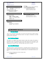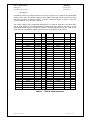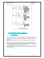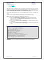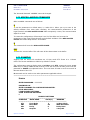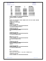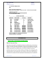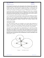
1
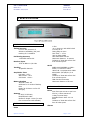
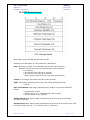
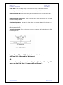
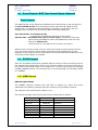
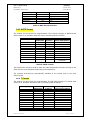
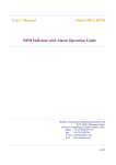
GPS masTER CLOCK
masibus
Model: MC-I
Doc Ref No: m05/om/101
Issue No:07
Jan 25, 2011
OPERATOR’S MANUAL
GPS masTER CLOCK
MASIBUS AUTOMATION & INSTRUMENTATION (P) LTD
B-30 GIDC, Electronics Estate, Gandhinagar – 382044, Gujarat, India
Ph No: 91-79-23287275/23287279
Fax No: 91-79-23287281/23287282
Email: [email protected], [email protected]
Operator’s Manual
Page 1 of 36
GPS masTER CLOCK
masibus
Model: MC-I
Doc Ref No: m05/om/101
Jan 25, 2011
Issue No:07
Website: www.masibus.com
CONTENTS
1. Introduction
2. Specifications
3. Time Signal Outputs
3.1
The 1 PPS Signal
3.2
The Event Signal
3.3
The IRIG-B Signal (Optional)
3.4
NTP / SNTP Time Protocol (Optional)
3.5
Event Outputs
3.6
RS232 Outputs
3.6.1 NMEA ($GPRMC) Format
3.6.2 NGTS Format
3.6.3 T-Format Format
4. Installation
4.1
Packing List
4.2
Mounting the Unit
4.3
Mounting the Antenna
4.4
Antenna Cable
4.5
Suggested Assembly Order
4.6
Self Monitoring
4.7
Available Alarms
4.8
Time Output Ports
5. Connection Diagram
6. User Configuration
6.1
Initializing the Configuration
6.2
Precautions
6.3
Configuration Command & Password
6.4
Communication Commands
6.5
Time Zone Offset Command
6.6
LCD Display Commands
6.7
Command For Selection of Format on COM2
6.8
Event Command
6.9
Additional Event Outputs.
6.10 COMMAND to set default IP address,Subnet mask & Gateway
6.11 Password Command
6.12 Miscellaneous Commands
6.13 Example
Appendices
A. The Global Positioning System (GPS)
B. Applicability of GPS masTER CLOCK
C. Health & Safety Statement
Operator’s Manual
Page 2 of 36
GPS masTER CLOCK
masibus
Model: MC-I
Doc Ref No: m05/om/101
Jan 25, 2011
Issue No:07
1. INTRODUCTION
Masibus’ GPS masTER CLOCK has been developed to address key power and process
industry timing requirements. Whether it’s the monitor, control or analysis of the power
system, the GPS masTER CLOCK is the cost-effective GPS time synchronization solution.
To begin with, the GPS masTER CLOCK offers superb timing accuracy (±1µs to UTC).
Using GPS satellites, it generates extremely accurate output pulses and time codes in
multiple formats.
The GPS masTER CLOCK synchronizes a wide variety of microprocessor-based power
system equipment including: SCADA systems, remote terminal units (RTUs), protection
relays, sequence of event recorders, digital fault recorders, tariff meters, Slave Display
Units, Data Loggers and other Intelligent Electronic Devices (IEDs). Being a Field
programmable device using HyperTerminal, a very common application in Windows, the
GPS masTER CLOCK allows the user to alter the settings or choose from Time codes. The
serial port COM2 (RS232) is provided for that purpose. Each output can feed directly to
different areas through electrically isolated ports which ensure reliable operation in a
harsh substation environment.
The GPS masTER CLOCK generates a wide range of timing signals via six output ports.
The GPS masTER CLOCK is defaulted with two serial ports, a 1 PPS Port, 1 RJ-45 NTP
port and four relay outputs. A fixed serial port provides NMEA 0183 $GPRMC format
data. Second serial port is configurable for either NGTS or T-format. Another fixed
output provides a very accurate pulse per second with accuracy of ±1µs to UTC. Optional
outputs include an IRIG-B DC Level Shift, an IRIG-B Amplitude Modulated (AM) time
code signals and 4 additional event outputs. Time synchronization protocol (NTP)
standard as Server/Broadcast mode implemented in GPS to provide time synchronization
to different slaves supporting NTP protocols.
All GPS masTER CLOCK units feature a front panel display, giving both installation teams
and users visual feedback about the time data being generated on the outputs. LED
indicators provide “at a glance” status information.
The optimized Receiver/Antenna system employed in the GPS masTER CLOCK provides
time information from the GPS satellite constellation. Dynamic T-RAIM processing is used
to eliminate any aberrant satellite signals from the timing solution. The result is timing
precision on all outputs with accuracy similar to that normally seen only in laboratory
instruments.
The GPS masTER CLOCK unit occupies the size of 19” x 12” x 3.5”. It is supplied
complete with all hardware and software required for the installation, including the
Antenna, Antenna mounting kit, 10 meters Antenna cable, 3 meters RS-232 cable and
10 meters RG58 Co-axial cable.
Operator’s Manual
Page 3 of 36
GPS masTER CLOCK
masibus
Model: MC-I
Doc Ref No: m05/om/101
Jan 25, 2011
Issue No:07
2. SPECIFICATIONS
RECEIVER CHARACTERISTICS
1 PPS
±1 µs Accuracy with GPS locked
TTL into 50 Ω
Rising Edge on time
Rise Time: < 15 ns
200 ms Pulse Width
Rear Panel BNC Female
Maximum Distance: 10 meters
Isolation of 2000 MΩ at 500 VDC
from all other ports.
Timing Accuracy
<2 ns in the presence of
Selective Availability (SA) and
tracking of 12 satellites
Positioning Accuracy
<25m SEP without SA
Receiver Input
1575.42 MHz L1 C/A Code
Serial
NMEA-0183-$GPRMC on COM 1
NGTS/ T-Format on COM 2
9600-8-N-1 on parameters COM1
4800/9600-7/8-N/E/O-1/2 on
COM2
Isolation of 2000 MΩ at 500 VDC
from all other ports.
DB9 Female Connectors
Maximum Distance of 50 mts.
Tracking
12 parallel channels
Acquisition Time
Hot Start: <25 s
Warm Start: <50 s
Cold Start: < 200 s
Memory Backup
Internal 5 mAh cell
Sufficient for 2 weeks of backup
time
Needs 24-36 hours run for full
charging
Antenna
L1 GPS, 25 dB Gain,
RG8/58/9913 Cable
Maximum length: 100m (In noise
free environment with LMR400)
OPTIONAL OUTPUTS
Event
One Event per minute or per hour
350 DC, 120mA maximum
8-Way Terminal Strip
Suitable Electric Wire: 22~14
AWG
Isolation of 2000 MΩ at 500 VDC
from all other ports
FIXED OUTPUTS
Alarms
Pulse
Operator’s Manual
Page 4 of 36
GPS masTER CLOCK
masibus
Model: MC-I
Doc Ref No: m05/om/101
Jan 25, 2011
Issue No:07
Three Isolated Dry Contacts to
230 V AC, 10 A:
1. GPS Lost
2. Watchdog
3. Power Fail
8-Way Terminal Strip
Suitable Electric Wire: 22~14
AWG
IRIGB-TTL
Serial Code with DC Level Shift
TTL into 50 Ω
Rise Time: < 15ns
Rear Panel BNC Female
Maximum Distance: 10 meters
Isolation of 2000 MΩ at 500 VDC
from all other ports.
IRIGB-Modulated
1 KHz AM Signal
3:1 Modulation Ratio
0-10Vpp (Unloaded)
0-3 Vpp (50 Ω load)
Rear Panel BNC Female
150 Ω Output Impedance
Isolation of 2000 MΩ at 500 VDC
from all other ports.
Ethernet Output:
Time Synchronization protocols:
NTP/SNTP Server
[Factory settable]
NTP: Network Time Protocol
(All versions compatible)
TP: RFC- 1059, RFC- 1119, RFC1305
SNTP: RFC- 1361
Network Protocol OSI Layer4
Transport layer: UDP
Internet protocol: IPv4
Modes: Server / Broadcast
Protocol Time format: UTC
Protocol standard: Universal
Time Output port: Rear Panel
RJ-45
Network Interface: 1 x 10Mbps
Isolation of 2000 MΩ at 500 VDC
from all other ports.
ON Time: min. 200 milliseconds
and max 50% of period time set
for particular event
Event contact capacity: 350 DC,
120mA maximum
Isolation: 2000 MΩ at 500 VDC
from all other ports.
INTERFACE
Display
99x24 mm, 2x16 LCD with
Backlit
Displayed data
Time of Day (HH:MM:SS)
Day of week
Date (DD/MM/YY)
Latitude, Longitude, Height
Number of satellites available
Data Format on COM2
Parameters of both serial ports
GPS status information
Status LED
Power
PPS
Event
Watchdog
GPS Locked
:
:
:
:
:
Red
Red
Red
Red
Green
Programming
Using HyperTerminal in a local PC
via COM2
Programmable parameters:
• Global Time zone correction
• 12/24 Hrs Format of Time
• COM2 serial port setting
• COM2 data format selection
(NGTS or T-FORMAT)
• Duration of Programmable
repetitive event generation
output via dry contact (Per
Minute or Hour).
• Password Protection
Network Settings
Additional Event Outputs
Four independent configurable
Event outputs
Individual configurable time
period and pulse ON time through
COM2
Time Period: 1 to 86400 seconds
(24 Hr.) max
Operator’s Manual
•
•
IP address, Subnet mask,
Gateway configurable through
Telnet remote login.
All network configurations are
password protected.
Page 5 of 36
GPS masTER CLOCK
masibus
Model: MC-I
Doc Ref No: m05/om/101
Jan 25, 2011
Issue No:07
POWER SUPPLY
AC
: 90 to 260 V, 47-440 Hz, 1φ
DC
: 110-340 V
Power Consumption: 15W
Compliance: FCC-B, CISPR22-B,
EN55022-B, VCCI-B
Humidity
90% at +40° C (Non-condensing)
Conducted & Radiated Noise
Tested immunity to 10 KV
Ignition Transformer Noise
PHYSICAL DIMENSIONS
EXTRA MODULE (OPTIONAL)
19” Rack Mountable:
Width : 426 mm (18.35”)
Depth : 300 mm (11.84”)
Height : 2 U – 88 mm (3.46”)
Weight: 4 Kg
RS232-to-RS485 Converter
Maximum Distance: 1.2 km
Power Requirement: 24 V DC
ENVIRONMENT
Temperature
Operating: 0° C to +45° C
Storage: -40° C to +85° C
3. TIME SIGNAL OUTPUTS
3.1
The 1pps Signal
This is a very important timing signal. It is the TTL level pulse with a width of 200ms
isolated output coming from the GPS receiver. This 1pps is connected to the BNC
connector on the rear panel.
3.2
The Event Signal
The signal is an isolated event output through a static relay contact. This signal is
connected to two of the terminal of the 8 way barrier strip on the rear panel of the
device the event is assigned as isolated event; the frequency for this event can be
configured as 1 minute or 1 hour. The pulse width of the event is 1 second.
3.3
The IRIG-B Signal
The IRIG-B format is a serial format based on a message frame per second which is Coordinated with the synchronized 1pps time output pulse. There are two alternative forms
of output, a dc level shift output, and a modulated output. The modulation frequency is 1
KHz.
For each form of output there are three output codes:a. A Reference Mark
b. A logical 1
Operator’s Manual
Page 6 of 36
GPS masTER CLOCK
masibus
Model: MC-I
Doc Ref No: m05/om/101
Jan 25, 2011
Issue No:07
c. A logical 0
For IRIG-B, each one of these codes is 10 ms long, which is 10 cycles for the modulated
format. There are 100 possible codes per time frame, although not all of them are used.
The code sequence is shown in Table 1, and the waveforms shown in Figure 2. The day
number starts at 1 on the first of January.
The output voltage of the modulated waveform is 3 V peak to peak into a 50 ohms load.
The dc level output is TTL standard and the rising edge of the pulse is "On Time". 1 kHz
modulated IRIG-B signal is connected to BNC on the rear panel of the device. IRIG-B TTL
level signal is connected to a BNC connector on the rear panel of the device.
Position
Type
0
1
2
3
4
5
6
7
8
9
10
11
12
13
14
15
16
17
18
19
20
21
22
23
24
25
26
Reference Mark
Signal
Signal
Signal
Signal
Logical 0
Signal
Signal
Signal
Reference Mark
Signal
Signal
Signal
Signal
Logical 0
Signal
Signal
Signal
Logical 0
Reference Mark
Signal
Signal
Signal
Signal
Logical 0
Signal
Signal
Item
Digit
Seconds
Seconds
Seconds
Seconds
1
2
4
8
Seconds
Seconds
Seconds
10
20
40
Minutes
Minutes
Minutes
Minutes
1
2
4
8
Minutes
Minutes
Minutes
10
20
40
Hours
Hours
Hours
Hours
1
2
4
8
Hours
Hours
10
20
Position
Type
27 to 28
29
30
31
32
33
34
35
36
37
38
39
40
41
42 to 48
49
50 to 58
59
60 to 68
69
70 to 78
79
80 to 88
89
90 to 98
99
Logical 0
Reference Mark
Signal
Signal
Signal
Signal
Logical 0
Signal
Signal
Signal
Signal
Reference Mark
Signal
Signal
Logical 0
Reference Mark
Logical 0
Reference Mark
Logical 0
Reference Mark
Logical 0
Reference Mark
Logical 0
Reference Mark
Logical 0
Reference Mark
Item
Digit
Day
Day
Day
Day
1
2
4
8
Day
Day
Day
Day
10
20
40
80
Day
Day
100
200
Table 1 – IRIG B Code Sequence
Operator’s Manual
Page 7 of 36
GPS masTER CLOCK
masibus
Model: MC-I
Doc Ref No: m05/om/101
Jan 25, 2011
Issue No:07
3.4
NTP / SNTP Time Protocol (Optional):
3.4.1. Introduction:
NTP(Network time protocol) is a common method for synchronization of hardware clocks
in local and global networks. The software package NTP is an implementation of the
actual version 3 [Mills90], based on the specification RFC-1305 from1990 (directory
doc/NOTES).
Other NTP compatible Versions are NTPv1 (RFC-1059), NTPv2(RFC-1119), RFC-958.
GPS is being provided with Internal protocol based Universal time synchronization
protocol i.e. SNTP (Simple Network Time Protocol) / NTP (Network Time Protocol) used
to synchronize the various clocks of NTP clients to adjust with universal time. SNTP uses
the standard NTP timestamp format described in RFC-1305.
Network Time Protocol is widely used to synchronize the time for Internet hosts, routers
and ancillary devices to Coordinated Universal Time (UTC) as disseminated by national
standards laboratories.
Operator’s Manual
Page 8 of 36
GPS masTER CLOCK
masibus
Model: MC-I
Doc Ref No: m05/om/101
Jan 25, 2011
Issue No:07
3.4.2. NTP:
GPS time protocol is transmitted via RJ-45 connector on UDP layer (RFC-768) at 10 Mbps
provided on rear panel of GPS. GPS transmits NTP packets in various optional modes i.e.
Server / Server Broadcast depending on the applications of client module. NTP packets
involve the timestamp value according to UTC (Universal Time) time.
Server mode: GPS responses with current timestamp when the query is received from
client.
Broadcast mode: GPS broadcasts the NTP packet at fixed intervals to clients.
Note:
a) NTP Version, Mode value in NTP packet is factory set.
b) Network IP, Subnet Mask and Gateway of GPS can be changed through
Telnet. Refer document m05/om/101-3 Appendix E for configuring GPS
master clock as Telnet Server.
c) Refer document m05/om/101-1 Appendix C for configuring Windows XP PC
as NTP Client.
d) Refer document m05/om/101-1 Appendix D for configuring Unix PC as NTP
Client.
Above figure shows the example of NTP packet transmitted containing different
parameters.
Operator’s Manual
Page 9 of 36
GPS masTER CLOCK
masibus
Model: MC-I
Doc Ref No: m05/om/101
Jan 25, 2011
Issue No:07
3.4.3. NTP Packet format:
Above figure shows the NTP packet header format.
Following is the description of each parameter in NTP Packet:
leap 2-bit integer warning of an impending leap second to be inserted or
deleted in the last minute of the current month, coded as follows:
0 no warning
1 last minute of the day has 61 seconds
2 last minute of the day has 59 seconds
3 alarm condition (the clock has never been synchronized)
version. 3-bit integer representing the NTP version number.
mode 3-bit integer representing the mode, with values defined as follows:
4 server
Peer clock stratum 8-bit integer representing the stratum, with values defined as
follows:
0 unspecified or invalid
1 primary server (e.g., equipped with a GPS receiver)
2-255 secondary server (via NTP)
Polling interval 8-bit signed integer representing the maximum interval between
successive messages.
Clock precision 8-bit signed integer representing the precision of the system clock. GPS
is having clock precision of 1 us (I microseconds = 0.000001s)
Operator’s Manual
Page 10 of 36
GPS masTER CLOCK
masibus
Model: MC-I
Doc Ref No: m05/om/101
Jan 25, 2011
Issue No:07
Root Delay Total roundtrip delay to the reference clock, in NTP short format.
Root Dispersion Total dispersion to the reference clock, in NTP short format.
Reference clock id. 32-bit code identifying the particular server or reference clock.
GPS Global Positioning System
Reference clock update time Time when the system clock was last set or corrected,
in NTP timestamp format.
Originate timestamp Time at the client when the request departed for the server, in
NTP timestamp format.
Receive timestamp Time at the server when the request arrived from the client, in
NTP timestamp format.
Transmit timestamp Time at the server when the response left for the client, in NTP
timestamp format.
To configure PC as a NTP client, please refer document
m05/om/101-1 Appendix C document.
OR
You can Access Procedure for configuring Windows XP using NTP
server on the link http://support.microsoft.com/.
Operator’s Manual
Page 11 of 36
GPS masTER CLOCK
masibus
Model: MC-I
Doc Ref No: m05/om/101
Jan 25, 2011
Issue No:07
3.5
Event Outputs / BCD Time Format Output (Optional)
Event Outputs
The additional four event signals are available at the terminal strip on the rear panel of
the GPS masTER CLOCK. User can configure these relays through COM2 for time
ranging from 1 to 86400 seconds individually for separate event outputs. User can
configure their Time period as well as their ON time through COM2 port.
Time Period limit: 1 to 86400 seconds
(0 values are to inhibit/stop particular event output).
ON time limit: 200 milliseconds (min.) to 50% (max.) of particular event time
period. Ensure that ON time value of all additional events are to be
entered in milliseconds.
(If time period is 0, the ON time will be also 0 by default).
Whenever the new time period is set, the new event timing counter will start from the
very next minute and the contact will be energized after the settable time for that
particular event. Please ensure to switch power of the instrument OFF and ON once if the
event time period settings are changed.
3.6
RS232 Outputs
There are two RS232 serial ports equipped within the device. These two serial ports use
two separate high performance chips to get electrical isolation. Each serial port has its
own format of the timing strings. On serial port one, 9 ways D-type socket, the message
is NMEA ($GPRMC) format. The serial port two, 9 way D-type plug, the message is NGTS
or T-FORMAT.
3.6.1 NMEA Format
RMC RECORD FORMAT
The $GPRMC sentence contains time and date of position fix, speed and course
information.The following examples show the contents of a typical RMC sentence:
The settings for this serial format is 4800, 8, N, 1.
The full data message of this format shall consist of data fields as follows:
Field
Sentence ID
UTC Time
Status
Latitude
N/S Indicator
Longitude
E/W Indicator
Speed over ground
Operator’s Manual
Example
$GPRMC,
130525.00,
A,
4250.5589,
S,
14518.5084,
E,
000.1,
Comments
hhmmss.ss,
A = Valid/V = Invalid,
ddmm.mmmm,
N = North/S = South,
dddmm.mmmm,
E = East/W = West,
Knots,
Page 12 of 36
GPS masTER CLOCK
masibus
Model: MC-I
Doc Ref No: m05/om/101
Jan 25, 2011
Issue No:07
Course over ground
UTC Date
Magnetic variation
Magnetic variation
Checksum
Terminator
245.0,
291206,
,
,
*25
<CR><LF>
Degrees,
DDMMYY,
Degrees,
E = East/W = West,
*CC
Non-printing characters
Table 3: RMC Record Selection
3.6.2 NGTS Format
The settings for this format are programmable. The full data message of NGTS format
shall consist of 14 printable characters and a concluding CRLF as follows:
Description
Code Identification
Year in Century
Month
Day of Month
Day of Week
Hours
Minutes
GMT Marker
Validity Marker
CRLF
Number of
Characters
1
2
2
2
1
2
2
1
1
2
Character
Position
1
2,3
4,5
6,7
8
9,10
11,12
13
14
15,16
Range of
Value/Information
Capital T
0 to 99
1 to 12
1 to 31
1 to 7
0 to 23
0 to 59
0 or 1
0 or 1
Non-printing
character
Table 4: NGTS Format
The transmission sequence shall be from the Code Identification character through to the
CRLF with the most significant digits being transmitted first.
The message shall become automatically available at one second prior to the clock
minute epoch.
3.6.3
T-Format
The settings for this format are programmable. The full data message of T-format shall
consist of 21 printable characters with a concluding CRLF as follows:
Description
Code Identification
Divider
Year in Century
Divider
Month
Divider
Day of Month
Divider
Day of Week
Divider
Hours
Operator’s Manual
Number of
Characters
1
1
2
1
2
1
2
1
1
1
2
Character
Position
1
2
3,4
5
6,7
8
9,10
11
12
13
14,15
Range of
Value/Information
Capital T
:
0 to 99
:
1 to 12
:
1 to 31
:
1 to 7
:
0 to 23
Page 13 of 36
GPS masTER CLOCK
masibus
Model: MC-I
Doc Ref No: m05/om/101
Jan 25, 2011
Issue No:07
Divider
Minutes
Divider
GMT Marker
Validity Marker
CRLF
1
2
1
1
1
2
16
17,18
19
20
21
22,23
:
0 to 59
:
0 or 1
0 or 1
Non printing character
Table 5: T- Format
4. INSTALLATION
4.1
Packing List
Each GPS masTER CLOCK is shipped with the following:
• GPS masTER CLOCK, Model MC-I time source with Regular outputs
• User Manual (This Document)
• Timing 3000 GPS antenna
• Antenna Mounting Kit
• 10 meters LMR- 195 Antenna Cable with N-to-BNC connectors
• 19” Rack mounting plate and fasteners
• 3 meters RS-232 Interface cable (Male to Female)
• 10 meters RG-58 Co-axial cable with BNC Male Connectors
• masTER SYNC Software for PC Synchronization
4.2
Mounting the Unit
The GPS masTER CLOCK is designed to be mounted in a 19 inch rack, but may be used
on a bench. The unit is attached with to the rack mount via four screws in the four
corners of the front panel.
The device should be installed inside a control room or suitable place without directly
effected by the changing of the condition of the weather. The environment temperature
should meet the requirement of the device.
4.3
Mounting the Antenna
The Antenna should be located in a position with as clear a view of the sky as possible,
over as wide an angle as possible. An absolute minimum is for it to have a view of 90%
of the sky. It should be mounted at least 0.5m clear of near by walls or other objects.
The antenna should also be mounted in a “Lightning-protected zone”, as far as is
possible. In practice, this means ensuring that there is at least one other ground-bonded
structure located in the same rooftop area (e.g. lightning rod) that reaches significantly
higher than the top of the GPS antenna. The GPS antenna should be mounted so that it
lies within a 45-degree angle “skirt” from the top of the other ground-bonded structure.
The GPS antenna mount itself should also be securely bonded directly to the building
protection ground – and not connected via any other grounded structures.
The mounting kit can be fastened to wall or fitted to the pipe using the screws supplied.
The antenna should be first placed through the hole of the mounting kit and then the
antenna cable should be fitted. The antenna erection at right angle wrt the ground is a
must.
Operator’s Manual
Page 14 of 36
GPS masTER CLOCK
masibus
Model: MC-I
Doc Ref No: m05/om/101
Jan 25, 2011
Issue No:07
4.4
Antenna Cable
The cable used must be with sufficient shielding. If the shielding is not sufficient, the
cable should not be in close proximity to power or other RF cables carrying transmitter
signals- in particular, parallel runs are to be avoided if possible. If such runs are
absolutely unavoidable, a minimum separation of 30 cm may be used as a guideline.
The GPS receiver embedded in the GPS masTER CLOCK has excellent OOB rejection
characteristics, as does the antenna itself. However, sound engineering practice should
not rely on these factors alone to guarantee performance. Careful installation will
enhance the long-term reliability and on-going stability of the GPS masTER CLOCK.
The maximum length of the cable is 100 meters when the LMR400 or Belden 9913 cable
is used. If the distance to be carried.
4.5
Suggested Assembly Order
The installation of GPS masTER CLOCK is very simple. Follow these steps:
•
•
•
•
•
Connect GPS receiver antenna. The antenna should be at sufficient height and in
open surrounding, with no obstacles nearby. Please follow the above stated
guidelines.
Make sure your power supply is in compliance with the specification and then
connect power supply.
Make the connections between time signal outputs and corresponding devices.
Connect the alarm signals to respective devices.
Figure 4 show the views of front panel and rear panel of the GPS masTER
CLOCK device respectively.
o
o
On the front panel of the device, there is a 2*16 characters LCD display.
There are five LEDs. These LEDs indicate the status of the device.
LED ‘POWER’ is the indicator for power supply.
Operator’s Manual
Page 15 of 36
GPS masTER CLOCK
masibus
Model: MC-I
Doc Ref No: m05/om/101
Jan 25, 2011
Issue No:07
LED ‘GPS LOCKED’ is the indicator for GPS locked. LED ‘EVENT’ is
the indicator for event output.
LED ‘1 pps’ is the indicator for one pulse per second output.
LED ‘WATCHDOG’ will be lit only when the application program has
been stopped for some reason.
All wiring connections are located on the rear panel of the device. Power supply
connector and one power supply fuse is also present at the rear panel.
o ANTENNA is used for connection of the GPS receiver antenna.
o COM1 is a 9 way D-type socket and the time message is NMEA ($GPRMC)
format on this serial communication port.
o COM2 is a 9 way D-type plug and the time message is standard NGTS or
T-FORMAT on this serial port.
o There are also three BNC connectors on the rear panel.
One with label ‘1PPS’ is the TTL level output of one pulse per
second signal.
One with label ‘IRIG-B TTL’ is the dc level shift IRIG-B signal output.
One with label ‘IRIG-B MOD’ is the modulated 1 KHz IRIG-B signal
output.
o NTP is RJ-45 female Ethernet connector provides NTP (Ethernet) output for
synchronization of NTP clients with GPS.
o Three pairs of alarm contacts are located between terminals 1 and 2,
terminals 3 and 4, terminals 5 and 6 respectively. They are assigned as
‘WATCHDOG’, ‘POWER FAIL’ and ‘GPS LOST’ accordingly.
o Optional output- There are 4 additional event outputs/contacts EVENT1,
EVENT2, EVENT3, EVENT4 provided on GPS rear terminal each with 350
VAC @ 120mA (max) capacity.
•
•
On first installation after about 15 days of off-state, the instrument may
initially show incorrect time because the battery of the receiver could be
discharged. It is required to run the system for 24 hours continuously to
completely recharge the battery and with antenna, so that it can get the
correct time.
4.6
SELF MONITORING
After the connections of power supply and GPS antenna, the device is ready to be
switched on.
• As soon as power is switched on, the green LED ‘POWER’ will be lit.
• The LCD display will also be lit and display some message as shown in figure 5(a)
to 5(d).
• The first screen of the LCD display is the name of manufacturer (Figure 5(a)). The
second screen is the message for settings of two serial communication ports. The
third screen is name of the device and the message ‘Connecting….’ will be
displayed until the device locks with the GPS receiver signal. This may be as long
as a few minutes.
• For the first time when the device is switched on, the exact location will not be
available for 2-15 minutes after the GPS has locked. This will depend on the
duration the device has been switched off and the distance the device has been
moved.
• After the device is locked with satellite signals, the green LED ‘GPS LOCKED’ will
be lit. The LCD display will restore to normal display situation. The normal display
screen shown as in Figure 5(d).
Operator’s Manual
Page 16 of 36
GPS masTER CLOCK
masibus
Model: MC-I
Doc Ref No: m05/om/101
Jan 25, 2011
Issue No:07
4.7
AVAILABLE ALARMS
Three alarm contacts are available on the connector block. They can be used to indicate
operation of the instrument to any remote device. The alarm contacts are all dry
contacts with ratings as detailed in the specification. They are all in open positions when
the system is working correctly, and closed in the event of a failure.
The events covered are:
(a) No power to the instrument
(b) Watchdog failure (i.e. firmware problem)
(c) GPS not locked.
Alarm (a) can be checked by switching the instrument off and checking that the contact
closes. Alarm (b) cannot be checked on site, and alarm (c) should give an alarm when
the instrument is first switched on before the clock synchronizes.
Operator’s Manual
Page 17 of 36
GPS masTER CLOCK
masibus
Model: MC-I
Doc Ref No: m05/om/101
Jan 25, 2011
Issue No:07
MASIBUS AUTO. &
INSTR. PVT. LTD.
Figure 5.a
COM 1: 9600 - N - 8 - 1
COM 2: 9600 - N - 8 - 1
Figure 5.b
GPS masTER CLOCK
CONNECTING……...
Figure 5.c
TIME: 12 : 00 : 00
DATE: 01 / 01 / 07
Figure 5.d
Figure – 5
4.8
TIME OUTPUT PORTS
A wide range of time related output signals are available from this instrument to suit a
wide range of possible applications. To complete installation of the instrument all that
remains is to couple the required outputs to the associated equipment, taking due
account of permitted signal output levels as detailed in the specification section.
Operator’s Manual
Page 18 of 36
GPS masTER CLOCK
masibus
Model: MC-I
Doc Ref No: m05/om/101
Jan 25, 2011
Issue No:07
The following is a summary of the signals available from the various terminals, and
sockets.
Connector
9 pin D type
COM1
Signal
RS-232
9 pin D type
COM2
RS-232
Description
NMEA format message
Pin 2: Serial Receive
Pin 3: Serial Transmit (NMEA Output)
Pin 4: 1 PPS
Pin 5: Ground
Standard NGTS or T-FORMAT message
Input – Local PC configuration COM2 can be
programmed to give different output formats
if required.
Pin 2: Serial Receive
Pin 3: Serial Transmit (NGTS/T-Format Output)
Pin 4: 1 PPS (for T-Format)/ 1 PPM (for NGTS)
Pin 5: Ground
Programmable output (Assigned as isolated event),
it is an isolated event through a static relay,
this event is indicated by the ‘EVENT’ LED.
Event
Terminal strip
WATCHDOG
Terminal
Strip-2
BNC
BNC
BNC
RJ-45
POWER
GPS LOCK
Event - 1
Event - 2
Event - 3
Event – 4
TTL Pulse
AM Signal
TTL String
Ethernet
Alarm output when firmware is not working properly.
Alarm output when there is a power failure.
Alarm output when there is a GPS sync loss.
Additional Programmable output
Additional Programmable output
Additional Programmable output
Additional Programmable output
1pps signal
1 kHz IRIG B Modulated Signal
IRIG B DC Shift Signal
SNTP Output/NTP Output
Table 6: Available Time Outputs
Operator’s Manual
Page 19 of 36
GPS masTER CLOCK
masibus
Model: MC-I
Doc Ref No: m05/om/101
Jan 25, 2011
Issue No:07
5. CONNECTION DIAGRAM
Fig 6: Connection Diagram with additional Event Outputs
Operator’s Manual
Page 20 of 36
GPS masTER CLOCK
masibus
Model: MC-I
Doc Ref No: m05/om/101
Jan 25, 2011
Issue No:07
6. USER CONFIGURATIONS
GPS masTER CLOCK offers facility to the users for configuring communication
parameters of serial port COM2, Time format Option of COM2, Display Format on LCD as
well as Event Mode.
• The communication parameters include baud rate, number of stop bits and parity.
• The user is free to choose either NGTS or T-Format on COM2.
• The LCD Display Format includes Hour Mode and Time Format (UTC/IST).
• The Event Mode can be either one event per minute or per hour.
• The user can enter the time offset of the time zone, where the unit is to be
installed.
• The user can change IP address, Subnet Mask & Gateway of GPS master clock.
Configuration requires a standard 9-way D-type RS-232 cable and standard
communication software in the PC, such as HyperTerminal. HyperTerminal is available
in every Windows based PC on the link shown in figure 7.
Fig 7: Path of HyperTerminal
6.1
INITIALIZING THE CONFIGURATION
The cable requirement for the GPS masTER CLOCK configuration is shown in figure 8.
Connect one end of the cross cable to the COM2 of the GPS masTER CLOCK and other
end to an available serial port on your local PC.
Operator’s Manual
Page 21 of 36
GPS masTER CLOCK
masibus
Model: MC-I
Doc Ref No: m05/om/101
Jan 25, 2011
Issue No:07
Open the HyperTerminal and start new connection on COMx of your PC. (x can be
any available serial RS232 port number)
In using HyperTerminal, it is recommended to select File\Properties\Settings and
set Emulation to ANSI, to avoid auto-detect making unwanted changes to the settings.
Fig 8: Cable requirement for configuration
The port settings in HyperTerminal and the COM2 port of the GPS masTER CLOCK
must match each other for fruitful communication. The settings of COM2 of GPS
masTER CLOCK are defaulted to 9600 baud, 8, N, 2 and may be checked by observing
the LCD on boot up. The settings of the HyperTerminal must be set same as that
observed on LCD to initialize the communication. This is shown in figure 9 and 10. In
order to configure the settings, first disconnect (See step 2 on page 20) the
communication on the HyperTerminal.
Once the communication parameters are set as that of GPS masTER CLOCK, you will
get NGTS data by default on the HyperTerminal, as shown in figure 11.
COM 1: 9600 - N - 8 - 1
COM 2: 9600 - N - 8 - 1
Fig 9: COM port Settings of GPS masTER CLOCK
Operator’s Manual
Page 22 of 36
GPS masTER CLOCK
masibus
Model: MC-I
Doc Ref No: m05/om/101
Jan 25, 2011
Issue No:07
Fig 10: Configuration of Settings of HyperTerminal
--------------------------------------------T0701022120101
T0701022120201
T0701022120301
T0701022120401
--------------------------------------------Fig 11: Default NGTS Data on HyperTerminal
This was the journey to get time format on RS-232. To configure the RS-232
communication, the user needs to follow the below listed commands.
6.2
PRECAUTIONS
1. The unit will enter the configuration as soon as it will receive CONFIG command
followed by an “Enter”.
2. Once the configuration mode is entered, the unit will stop sending time frames on
COM2.
3. Any pressing of “Enter”, if not followed by any command, will put the unit out of
configuration mode and the time frames will start getting transmitted from COM2
again.
4. In case of improper entry of command, following message will appear on the
screen:
----------------------------------------------------------------INVALID COMMAND
TO SET DEFAULT CONFIGURATION PRESS ‘D’
TO CONTINUE PRESS ENTER
6.3
CONFIGURATION COMMANDS & PASSWORD
CONFIG
This command lets the user to enter in the configuration mode. Once writing ‘CONFIG’
and pressing ‘Enter’ key, will stop the display of the T-format data and will ask the user
to enter the password, as shown below:
---------------------------------------------T0701022120401
T0701022120501
CONFIG
ENTER PASSWORD : _
----------------------------------------------
ENTER PASSWORD
There are two passwords for GPS masTER CLOCK. One is user-defined password, which
can be changed by the user. By default, this password is ‘MASIBUS’. Another is
Immortal Password that cannot be changed by any user and it kept confidential to
Masibus Service Engineers. Users are asked to change the user-defined password.
Operator’s Manual
Page 23 of 36
GPS masTER CLOCK
masibus
Model: MC-I
Doc Ref No: m05/om/101
Jan 25, 2011
Issue No:07
Enter the correct password and press Enter. As a result, it will ask the user to enter any
command to configure the parameters. This is shown below:
------------------------------------------------------ENTER PASSWORD : *******
PASSWORD OK
ENTER COMMAND TO CONFIGURE PARAMETER.
H FOR HELP MENU.
L FOR PRESENT SETTINGS.
Z FOR TIME-ZONE SETTINGS.
_
--------------------------------------------------------If the entered password is wrong, the following message will be displayed:
-------------------------------------------------------ENTER PASSWORD : ****
WRONG PASSWORD
TO CONTINUE PRESS ENTER
T0701022120501
…
-------------------------------------------------------To enter into the configuration mode, again write ‘CONFIG’ and enter correct password.
L: LIST PRESENT CONFIGURATIONS
On writing ‘L’, it will display the present settings of the parameters of GPS masTER
CLOCK.
---------------------------------------------------------------------------------------------…
H FOR HELP MENU.
L FOR PRESENT SETTINGS.
Z FOR TIME-ZONE SETTINGS.
L
PRESENT SETTINGS
-----------------------------------------------------------------------COMMAND
MODE NAME
VALUE(x)
MEANING
-----------------------------------------------------------------------STx
Hour Mode
2
24 Hour Mode
SBx
Baud Rate
96
9600 Baud Rate
SPx
Parity
0
Parity None
SSx
Stop Bit
1
1 Stop Bit
SUx
Time Format
1
UTC time
Tx
Transmit Mode
1
NGTS Mode
Ex
Event Mode
1
Minute Mode
ET1
Addi. Event1
00000001
Second Mode
ET2
Addi. Event2
00000001
Second Mode
ET3
Addi. Event3
00000001
Second Mode
ET4
Addi. Event4
00000001
Second Mode
EW1
Event1 ON Time
00000200
m.second Mode
EW2
Event2 ON Time
00000200
m.second Mode
EW3
Event3 ON Time
00000200
m.second Mode
EW4
Event4 ON Time
00000200
m.second Mode
---------------------------------------------------------------------------
Operator’s Manual
Page 24 of 36
GPS masTER CLOCK
masibus
Model: MC-I
Doc Ref No: m05/om/101
Jan 25, 2011
Issue No:07
ENTER COMMAND TO CONFIGURE PARAMETER
OR PRESS ENTER TO CONTINUE.
----------------------------------------------------------------------------------------------
H: HELP
The ‘H’ command will list all the commands to configure GPS masTER CLOCK. If the
user presses the ‘Enter’ key before writing any command, operator has to enter
‘CONFIG’ and password again. Any pressing of ‘Enter’ instead of command will result in a
jump out of the configuration mode.
H command will show the various possible values applicable to be entered for the
particular parameter.
The HELP is displayed below:
---------------------------------------------------------------------------------------------…
H FOR HELP MENU.
L FOR PRESENT SETTINGS.
Z FOR TIME-ZONE SETTINGS.
H
GPS MASTER CLOCK SYSTEM
Version No: 101
UART commands:
STx : Set hour mode to 12 or 24.(For Display)
1 : set it to 12 hour mode.
2 : set it to 24 hour mode.
SBxx : Set baud rate.
48 : 4800 baud rate.
96 : 9600 baud rate.
SPx : Set parity bit.
0 : parity bit set to none.
1 : parity bit set to odd.
2 : parity bit set to even.
SSx : Set stop bit.
1 : stop bit set to 1.
2 : stop bit set to 2.
SUx : Set UTC OR IST time. (default set to 2 )
1 : UTC time.
2 : LOCAL time.
H : Show help test.
Tx : Set transmit mode.
1 : ngts mode.
2 : t-format mode.
Ex : Set Event mode.
1 : minute mode.
2 : hour mode.
P(password) : To change password.(max upto 9 character.)
R : Reset the controller.
D : Set to Default Setting.
ETH0: Set to Default Network Settings.
ESC : Reset the receive buffer.
ETx : To configure additional Events.
Operator’s Manual
Page 25 of 36
GPS masTER CLOCK
masibus
Model: MC-I
Doc Ref No: m05/om/101
Jan 25, 2011
Issue No:07
EWx : To configure additional Events ON Time.
ENTER COMMAND TO CONFIGURE PARAMETER
OR PRESS ENTER TO CONTINUE.
Note: a) Parameter S : To save Parameters is not used as it it reserved for
future use.
6.4
COMMUNICATION COMMANDS
The communication commands change the parameters of serial communication port of
the GPS masTER CLOCK. These include SBxx, SPx and SSx.
These commands first change the configuration of COM2 of the GPS masTER CLOCK,
hence for the moment, the communication between the unit and HyperTerminal stops.
To reinitialize the communication, first disconnect the link, enter into the settings of
the HyperTerminal and set it same as the present setting of GPS masTER CLOCK.
Again connect the link.
SBxx
1.
Suppose that the desired baud rate is 4800, the command should be SB48 (See
H: HELP). This will display following on the HyperTerminal:
------------------------------------------------------------------ENTER COMMAND TO CONFIGURE PARAMETER
OR PRESS ENTER TO CONTINUE.
SB48
------------------------------------------------------------------Now, the communication must have stopped.
2.
Disconnect the link by a right click on Call\disconnect.
3.
Enter the settings by following the path:
File\Properties\Connect To\Configure.
Operator’s Manual
Page 26 of 36
GPS masTER CLOCK
masibus
Model: MC-I
Doc Ref No: m05/om/101
Jan 25, 2011
Issue No:07
4.
Set the baud rate to 4800 and check for other parameters to be same as that of
the GPS masTER CLOCK.
5.
After setting the parameters, reconnect the link by right click on Call\Call.
6.
Now press ESC and Enter keys.
7.
Once the connection is reestablished, the time data will again be displayed on the
HyperTerminal.
Now, without pressing ‘Enter’ anymore times, if you enter any of the commands listed in
help, you do not need to reenter the ‘CONFIG’ and password. Press ‘L’ to check whether
the baud rate change was accepted or not.
SPx
The change of parity configuration can be done using this command. Different options for
the parity settings are as below:
SP0: No Parity
8 data bits
SP1: Odd Parity
7 data bits
SP2: Even Parity
7 data bits
Operator’s Manual
Page 27 of 36
GPS masTER CLOCK
masibus
Model: MC-I
Doc Ref No: m05/om/101
Jan 25, 2011
Issue No:07
Same as SBxx command, the communication stops as soon as you finish the command
and press ‘Enter’ once. This is because the protocol settings at GPS masTER CLOCK
and HyperTerminal do not match. To correct this, follow the steps 2 and 3 of SBxx
command. Now correct the parameter to match with desired/set ones. In this case, take
care of changing the databits to 7, when the parity is either even or odd.
After setting the parity in this setting window, follow the steps 5 and 6 of the SBxx
command. The time data will again reappear. You can check present settings using ‘L’
command.
SSx
The number of stop bits in the serial communication can be set as 1 or 2 using this
command. The options are simply two:
SS1: One stop bit
SS2: Two stop bits
The steps to follow are same as SBxx and STx command.
6.5
TIME ZONE OFFSET COMMAND
Z
This command is to enter the time offset of any particular location with reference to the
UTC. Every country has some time zone offset in its local time wrt the UTC. The table of
the time zone can be found from Internet. The following is the example of the entering a
time zone.
Remember that the time zone will put its direct effect of the IRIG-B signal while it will
affect the NGTS and T-frames only if the unit is set in the LOCAL TIME DISPLAY mode,
using the SUx command as explained further.
Time zone offset value should be between time ranges of -12:00 to +12:00.
Time offset value apart from above range will be considered as INVALID command.
Z
ENTER THE TIME-ZONE OFFSET ADDED WITH THE DAY-LIGHT SAVING
TIME, IF APPLICABLE.
FORMAT: (+/-)(HH):(MM)
ENTER NOW:
-02:00
COMMAND COMPLETE
ENTER COMMAND TO CONFIGURE PARAMETER.
TO CONTINUE PRESS ENTER
6.6
LCD DISPLAY COMMANDS
The 2x16 LCD on the front panel of the GPS masTER CLOCK displays time as either
UTC or IST and 12 Hour/24 Hour mode. The commands to set these modes are as
explained below:
Operator’s Manual
Page 28 of 36
GPS masTER CLOCK
masibus
Model: MC-I
Doc Ref No: m05/om/101
Jan 25, 2011
Issue No:07
STx
Suppose that initially the display is in 12 hour mode. The command to change it to 24
hour mode will be ST2.
If the hour mode were 24 initially, then the command to convert it in 12 hour mode will
be ST1.
SUx
This command is used to select the displayed time from UTC or Local Time. There is a
predefined time zone offset of any country’s Local time wrt the UTC. The selection of
local time using this command will add the offset to the GMT for display on the LCD as
well as in the T-format and NGTS frame. The offset is entered by the user using ‘Z’
command that is explained later.
The commands for selection of UTC or Local Time are:
SU1: UTC Time
SU2: LOCAL Time
6.7
COMMAND FOR SELECTION OF FORMAT ON COM2
The COM2 of GPS masTER CLOCK allows the time format in two different ways: NGTS
format and T-format. These formats are already explained before. These commands are:
T1:
NGTS mode
T2:
T-format mode
Remember that T-format sends the time frame each second while the NGTS sends the
time frame each minute.
6.8
EVENT COMMAND
The relayed event signal is available at the terminal strip on the rear panel of the GPS
masTER CLOCK. This signal triggers relay either every minute or every hour based on
the configuration set by the command as listed below:
E1:
1 Minute mode
E2:
1 Hour Mode
6.9
ADDITIONAL EVENT’S COMMAND
The additional four event signals are available at the terminal strip on the rear panel of
the GPS masTER CLOCK. User can configure these relays through COM2 for time
ranging from 1 to 86400 seconds individually for separate event outputs. User can
configure their Time period as well as their ON time through COM2 port.
Time Period limit: 1 to 86400 seconds
(0 values are to inhibit/stop particular event output).
ON time limit: 200 milliseconds (min.) to 50% (max.) of particular event time
period. Ensure that ON time value of all additional events are to be
entered in milliseconds.
(If time period is 0, the ON time will be also 0 by default).
Operator’s Manual
Page 29 of 36
GPS masTER CLOCK
masibus
Model: MC-I
Doc Ref No: m05/om/101
Jan 25, 2011
Issue No:07
Whenever the new time period is set, the new event timing counter will start from the
very next minute and the contact will be energized after the settable time for that
particular event. Please ensure to switch power of the instrument OFF and ON once if the
event time period settings are changed.
ETx
This command is used to configure Time Period of Additional Events. These Events can
be configured to trigger at every second to every 86400 seconds (24 hr.). These
configuration commands are listed below:
ET1:
ET2:
ET3:
ET4:
Additional
Additional
Additional
Additional
Event1
Event2
Event3
Event4
EWx
This command is used to configure ON Time of Additional Events. These Events can be
configured to stay ON for a minimum 200 millisecond to 50% of its period. These
configuration commands are listed below:
EW1:
EW2:
EW3:
EW4:
Event1
Event2
Event3
Event4
ON
ON
ON
ON
Time
Time
Time
Time
NOTE: a) Please ensure that the instrument should be power switch OFF/ON after
changing the event time settings.
6.10 COMMAND to set default IP address,Subnet mask &
Gateway.
ETH0
This command is used to set default network settings of GPS masTER CLOCK.
Default network settings are,
IP Address
: 192.168.100.153
Subnet Mask : 255.255.255.0
Gateway
: 192.168.100.1
6.11 PASSWORD COMMAND
The user is allowed to change one password. The command for changing password is:
P (password)
The default password is ‘MASIBUS’. Suppose, user wishes to change it to ‘INDIA’, then
the command will be:
PINDIA
Remember that the password should not exceed 9 characters. If you try to keep a
password that has more than 9 characters, the system will show an error “Invalid
Command” and the previous password will be retained.
Operator’s Manual
Page 30 of 36
GPS masTER CLOCK
masibus
Model: MC-I
Doc Ref No: m05/om/101
Jan 25, 2011
Issue No:07
The Immortal Password ‘LAMBDA’ cannot be changed.
6.12 MISCELLANEOUS COMMANDS
Other available commands are as follows:
D
To set the parameters to default state, i.e. 9600-8-N-1. When you try to enter in the
default condition from some other condition, the communication parameters of the
HyperTerminal and GPS masTER CLOCK differ temporarily. Hence, the communication
stops for a while.
To restart the configuration, follow steps 2 and 3 of the SBxx and now set the
parameters of the HyperTerminal same as the default condition of the GPS masTER
CLOCK. Now follow steps 6 and 7 of the SBxx.
R
This command will reset the GPS masTER CLOCK.
ESC
To Reset the receive buffer. This will erase all the data written in the buffer.
6.13 EXAMPLE
Suppose that the initial LCD conditions are 12 Hour mode UTC. Event is in 1 Minute
mode. The format available on COM2 is by default T-format.
The configuration steps to display time in 24 Hour mode UTC, trigger the event at per
hour rate, to change COM2 format to NGTS, to set the time zone of India, and to set the
password to INDIA are explained below. The Local time of India is set 5 Hours and 30
Minutes ahead of the UTC.
H command can be used to view other parameters applicable values.
---------------------------------------------------------------------------------------------…
CONFIG
ENTER PASSWORD : *******
PASSWORD OK
ENTER COMMAND TO CONFIGURE PARAMETER.
H FOR HELP MENU.
L FOR PRESENT SETTINGS.
Z FOR TIME-ZONE SETTINGS.
L
PRESENT SETTINGS
----------------------------------------------------------------------COMMAND
MODE NAME
VALUE(x)
MEANING
-----------------------------------------------------------------------STx
Hour Mode
2
24 Hour Mode
SBx
Baud Rate
96
9600 Baud Rate
SPx
Parity
0
Parity None
SSx
Stop Bit
1
1 Stop Bit
Operator’s Manual
Page 31 of 36
GPS masTER CLOCK
masibus
Model: MC-I
Doc Ref No: m05/om/101
Jan 25, 2011
Issue No:07
SUx
Time Format
1
UTC time
Tx
Transmit Mode
1
NGTS Mode
Ex
Event Mode
1
Minute Mode
ET1
Addi. Event1
00000001
Second Mode
ET2
Addi. Event2
00000001
Second Mode
ET3
Addi. Event3
00000001
Second Mode
ET4
Addi. Event4
00000001
Second Mode
EW1
Event1 ON Time
00000200
m.second Mode
EW2
Event2 ON Time
00000200
m.second Mode
EW3
Event3 ON Time
00000200
m.second Mode
EW4
Event4 ON Time
00000200
m.second Mode
--------------------------------------------------------------------------ENTER COMMAND TO CONFIGURE PARAMETER
OR PRESS ENTER TO CONTINUE.
Z
ENTER THE TIME-ZONE OFFSET ADDED WITH THE DAY-LIGHT SAVING
TIME, IF APPLICABLE.
FORMAT: (+/-)(HH):(MM)
ENTER NOW:
+05:30
COMMAND COMPLETE
ENTER COMMAND TO CONFIGURE PARAMETER.
TO CONTINUE PRESS ENTERST2
COMMAND COMPLETE
ENTER COMMAND TO CONFIGURE PARAMETER.
TO CONTINUE PRESS ENTER
SU2
COMMAND COMPLETE
ENTER COMMAND TO CONFIGURE PARAMETER.
TO CONTINUE PRESS ENTER
T1
COMMAND COMPLETE
ENTER COMMAND TO CONFIGURE PARAMETER.
TO CONTINUE PRESS ENTER
E2
COMMAND COMPLETE
ENTER COMMAND TO CONFIGURE PARAMETER.
TO CONTINUE PRESS ENTER
PINDIA
COMMAND COMPLETE
ENTER COMMAND TO CONFIGURE PARAMETER.
TO CONTINUE PRESS ENTER
ET1
Event-1 Configuration
Please enter interval (Min. = 1 sec, Max. = 86400 sec):2
COMMAND COMPLETE
ENTER COMMAND TO CONFIGURE PARAMETER.
Operator’s Manual
Page 32 of 36
GPS masTER CLOCK
masibus
Model: MC-I
Doc Ref No: m05/om/101
Jan 25, 2011
Issue No:07
TO CONTINUE PRESS ENTER
EW1
Event-1 ON Time Configuration
Please enter interval (Min. = 200 m.sec, Max. = 50% Of Interval):1000
COMMAND COMPLETE
ENTER COMMAND TO CONFIGURE PARAMETER.
TO CONTINUE PRESS ENTER
L
PRESENT SETTINGS
-----------------------------------------------------------------------COMMAND
MODE NAME
VALUE(x)
MEANING
-----------------------------------------------------------------------STx
Hour Mode
2
24 Hour Mode
SBx
Baud Rate
96
9600 Baud Rate
SPx
Parity
0
Parity None
SSx
Stop Bit
1
1 Stop Bit
SUx
Time Format
1
UTC time
Tx
Transmit Mode
1
NGTS Mode
Ex
Event Mode
2
Minute Mode
ET1
Addi. Event1
00000002
Second Mode
ET2
Addi. Event2
00000001
Second Mode
ET3
Addi. Event3
00000001
Second Mode
ET4
Addi. Event4
00000001
Second Mode
EW1
Event1 ON Time
00001000
m.second Mode
EW2
Event2 ON Time
00000200
m.second Mode
EW3
Event3 ON Time
00000200
m.second Mode
EW4
Event4 ON Time
00000200
m.second Mode
--------------------------------------------------------------------------ENTER COMMAND TO CONFIGURE PARAMETER
OR PRESS ENTER TO CONTINUE.
APPENDICES
THE GLOBAL POSITIONING SYSTEM (GPS)
Need of Accurate Time
Most days as we go about our business we look at our watches ten or more times in
order to check "The Time". Our measurement of time has two components, the unit (the
second), by which we specify the duration of events, and the reference point which
enables us to use time in a general way. For example Greenwich Mean Time (GMT) is
based on observations of the transit of the sun in the sky at midday at Greenwich.
Scientists need a much more accurate method of measuring, and synchronizing time
than this method. This led quite early in the history of radio to the establishment of
standard frequency radio transmissions, which continue to the present. Since frequency
is measured in cycles/second, these transmissions automatically provide a standard for
Operator’s Manual
Page 33 of 36
GPS masTER CLOCK
masibus
Model: MC-I
Doc Ref No: m05/om/101
Jan 25, 2011
Issue No:07
the second as the unit of time. They also provide a time reference which is coded into
the modulation of the signal. With the development of very accurate clocks based on the
properties of atoms, it was found that the world did not rotate at a constant speed, and
therefore atomic clocks, which depend on vibrations within atoms, were adopted as the
standard, and Universal Co-ordinate Time (UTC) was established as the world standard.
In the power generation and distribution industry, synchronized time is important,
although the accuracy required varies with the application. If one is trying to compare
phase angles measured at different points in a transmission system without a direct
connection using synchronized clocks, it is impossible to achieve the accuracy needed to
be around 50 µs (for 1 degree accuracy) in the measurement.
To use synchronized clocks for fault location using traveling wave methods one needs to
get 1 µs accuracy. Till now, last two higher accuracies have been very difficult to obtain,
but they can now be obtained quite easily by making use of the Global Positioning
System (GPS). This has the advantage of being available world wide, and does not suffer
from the signal propagation problems associated with terrestrial standard radio
frequency transmissions.
Introduction to GPS
The Global Positioning System was developed by the United States Department of
Defense, with the object of making it possible (with suitable equipment) to find the
position of a receiver in terms of latitude, longitude, and height with a high degree of
accuracy. A system which can do this provides a universal means of aerial navigation.
The principle is very simple, although the implementation uses a great deal of modern
technology. If one considers Figure 1 which shows a flat plane. X and Y are two known
fixed points on the plane. P is an unknown point. If the distances PX and PY can be
measured, then the position of point P can be calculated. Actually there is an ambiguity
in that point P’ would also fit the measurements. This can be resolved if the position of a
third fixed point Z is known since PZ is different to P’Z. This can be summed up by
saying that the unknown point P lies at the intersection of three circles based on the
known points X, Y and Z.
Operator’s Manual
Page 34 of 36
GPS masTER CLOCK
masibus
Model: MC-I
Doc Ref No: m05/om/101
Jan 25, 2011
Issue No:07
When the plane becomes three dimensional spaces, the circles become spheres. The
intersection of two sphere is a circle, and the intersection of three spheres is a pair of
points analogous to the points P and P’ of the flat plane case. As for the flat plane case a
measurement from an extra fixed point is required to absolutely resolve the ambiguity,
although in many cases the ambiguous point would be below the surface of the world.
Thus to achieve the objective, GPS must provide accurate measurement of distance from
the unknown location of the receiver to 4 known points.
Electromagnetic radiation travels at a constant speed of approximately 300 m/µs, so if
one could measure the time for radio waves to travel to the unknown point from four
known points then one could calculate the position of the unknown point. This relaxation
makes the GPS system practical. The "fixed points" consist of an array of 24 satellites,
each of which are at a height of 20,183 km (10,899 nautical miles) and orbit the earth
every twelve hours. They are distributed between 6 orbits, which are evenly spaced
around the equator, and inclined at 55° to it. This means that a minimum number of the
satellites are always in view from any point in or over the world.
The complete system consists of 3 parts:
A. A Master Control Station
This is at Colorado Springs in America, and receives information on the status,
clock data and position of the satellites from 5 Monitoring stations, which are
spread around the World. It transmits control data to the satellites, via 3 up-link
stations, which are again spread around the world. This data is used to correct
the satellite clocks and to update their data on the orbits of all the satellites.
B. The Satellites
The satellites, each has 4 atomic clocks, are kept in synchronism with UTC via the
Up-links by the Master Control Station. They transmit navigational signals, which
include the identity of, system time, and the almanac of satellite orbits. The
transmission frequency is about 1.5 GHz, which means that signals are not
affected by weather.
C. The User’s Receiver
This must be able to simultaneously receive signals from at least 4 satellites.
Commercial receivers such as the GPS masTER CLOCK can deal with up to 12
signals. The receiver will process the 4 strongest signals and from them it
calculates the distances to the 4 satellites, and hence the position of the receiver,
and the correction necessary to its local clock to bring it into synchronism with
UTC.
The system is available for free. All the user needs to do is provide himself with a
suitable aerial and receiver. Navigational user’s main interest is in the positional
information, but as a consequence of being able to get this data, a local clock is available
which is synchronized with UTC to an accuracy of ±1 µs. The GPS masTER CLOCK
combines a GPS receiver with a microcomputer and buffers to provide a local time
source with a variety of outputs suitable for synchronizing a wide variety of equipment.
A. APPLICABILITY OF GPS MASTER CLOCK
The GPS Master Clock can be used wherever there is a requirement to accurately
synchronize equipment.
Typical applications include:
I. Digital Fault Recorders (DFR)
II. Sequence of Event Recorders (SER)
III. Supervisory Control and Data Acquisition Systems (SCADA)
Operator’s Manual
Page 35 of 36
GPS masTER CLOCK
masibus
Model: MC-I
Doc Ref No: m05/om/101
Jan 25, 2011
Issue No:07
IV. Power Line Fault Detection using Time Domain Reflectometer.
V. Integrated Alarm Management Systems
B. HEALTH & SAFETY STATEMENT
This product is checked and supplied in accordance with our published specifications and
used in normal or prescribed applications and within the parameters set for mechanical
and electrical performance. The product will not cause danger or hazard to health or
safety, provided that normal engineering and safety practices are observed and the
product is only used by trained and qualified persons.
All usage of this product must be in accordance with this manual. If there is any doubt
about any aspect relating to the correct use of the product, please contact:
Masibus Automation & Instruments (P) Ltd,
B-30 GIDC, Electronics Estate,
Gandhinagar – 382044.
Gujarat, India.
Telephone
Fax
: 00-91-79-23287275
: 00-91-79-23287281
This operators’ manual is published by Masibus Automation & Instruments (P) Ltd, for
use with the GPS masTER CLOCK instrument described herein. Masibus Automation &
Instruments (P) Ltd reserves the right to revise this manual without notice for any
reason. This includes but is not limited to the utilization of advances in technology, and
changes in the instrument or its configuration. Liabilities for difficulties arising from
unknown or unforeseen technical limitations are disclaimed.
Operator’s Manual
Page 36 of 36