1
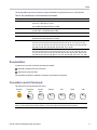
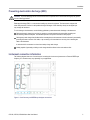
x
Tektronix BERTScope
Clock Recovery Instruments
ZZZ
Quick Start User Manual
*P071285201*
071-2852-01
xx
Tektronix BERTScope
Clock Recovery Instruments
ZZZ
Quick Start User Manual
This document supports BSA Software V10 and above.
www.tektronix.com
071-2852-01
Copyright © Tektronix. All rights reserved. Licensed software products are owned by Tektronix or its subsidiaries or suppliers, and are
protected by national copyright laws and international treaty provisions.
Tektronix products are covered by U.S. and foreign patents, issued and pending. Information in this publication supersedes that in all
previously published material. Specifications and price change privileges reserved.
TEKTRONIX and TEK are registered trademarks of Tektronix, Inc.
Contacting Tektronix
Tektronix, Inc.
14150 SW Karl Braun Drive
P.O. Box 500
Beaverton, OR 97077
USA
For product information, sales, service, and technical support:
In North America, call 1-800-833-9200.
Worldwide, visit www.tektronix.com to find contacts in your area.
Warranty
Tektronix warrants that this product will be free from defects in materials and workmanship for a period of one (1) year from the date of
shipment. If any such product proves defective during this warranty period, Tektronix, at its option, either will repair the defective
product without charge for parts and labor, or will provide a replacement in exchange for the defective product. Parts, modules and
replacement products used by Tektronix for warranty work may be new or reconditioned to like new performance. All replaced
parts, modules and products become the property of Tektronix.
In order to obtain service under this warranty, Customer must notify Tektronix of the defect before the expiration of the warranty period
and make suitable arrangements for the performance of service. Customer shall be responsible for packaging and shipping the
defective product to the service center designated by Tektronix, with shipping charges prepaid. Tektronix shall pay for the return of the
product to Customer if the shipment is to a location within the country in which the Tektronix service center is located. Customer shall
be responsible for paying all shipping charges, duties, taxes, and any other charges for products returned to any other locations.
This warranty shall not apply to any defect, failure or damage caused by improper use or improper or inadequate maintenance and
care. Tektronix shall not be obligated to furnish service under this warranty a) to repair damage resulting from attempts by personnel
other than Tektronix representatives to install, repair or service the product; b) to repair damage resulting from improper use or
connection to incompatible equipment; c) to repair any damage or malfunction caused by the use of non-Tektronix supplies; or
d) to service a product that has been modified or integrated with other products when the effect of such modification or integration
increases the time or difficulty of servicing the product.
THIS WARRANTY IS GIVEN BY TEKTRONIX WITH RESPECT TO THE PRODUCT IN LIEU OF ANY OTHER WARRANTIES,
EXPRESS OR IMPLIED. TEKTRONIX AND ITS VENDORS DISCLAIM ANY IMPLIED WARRANTIES OF MERCHANTABILITY OR
FITNESS FOR A PARTICULAR PURPOSE. TEKTRONIX' RESPONSIBILITY TO REPAIR OR REPLACE DEFECTIVE PRODUCTS
IS THE SOLE AND EXCLUSIVE REMEDY PROVIDED TO THE CUSTOMER FOR BREACH OF THIS WARRANTY. TEKTRONIX
AND ITS VENDORS WILL NOT BE LIABLE FOR ANY INDIRECT, SPECIAL, INCIDENTAL, OR CONSEQUENTIAL DAMAGES
IRRESPECTIVE OF WHETHER TEKTRONIX OR THE VENDOR HAS ADVANCE NOTICE OF THE POSSIBILITY OF SUCH
DAMAGES.
[W2 – 15AUG04]
Table of Contents
Table of Contents
General safety summary . . .. . .. . .. . .. . .. . .. . .. . .. . .. . .. . .. . .. . .. . .. . .. . .. . .. . .. . .. . .. . .. . .. . .. . .. . .. . .. . .. . .. . .. . .. . .. . .. . .. . .. . .. . .. .
Compliance information .. . .. . .. . .. . .. . .. . .. . .. . .. . .. . .. . .. . .. . .. . .. . .. . .. . .. . .. . .. . .. . .. . .. . .. . .. . .. . .. . .. . .. . .. . .. . .. . .. . .. . .. . .. . .. .
EMC compliance . . .. . .. . .. . .. . .. . .. . .. . .. . .. . .. . .. . .. . .. . .. . .. . .. . .. . .. . .. . .. . .. . .. . .. . .. . .. . .. . .. . .. . .. . .. . .. . .. . .. . .. . .. . .. . .. .
Safety compliance. .. . .. . .. . .. . .. . .. . .. . .. . .. . .. . .. . .. . .. . .. . .. . .. . .. . .. . .. . .. . .. . .. . .. . .. . .. . .. . .. . .. . .. . .. . .. . .. . .. . .. . .. . .. . .. .
Environmental considerations .. . .. . .. . .. . .. . .. . .. . .. . .. . .. . .. . .. . .. . .. . .. . .. . .. . .. . .. . .. . .. . .. . .. . .. . .. . .. . .. . .. . .. . .. . .. . .. . .
Preface .. . .. . .. . .. . .. . .. . .. . .. . .. . .. . .. . .. . .. . .. . .. . .. . .. . .. . .. . .. . .. . .. . .. . .. . .. . .. . .. . .. . .. . .. . .. . .. . .. . .. . .. . .. . .. . .. . .. . .. . .. . .. . .. .
Product description.. . .. . .. . .. . .. . .. . .. . .. . .. . .. . .. . .. . .. . .. . .. . .. . .. . .. . .. . .. . .. . .. . .. . .. . .. . .. . .. . .. . .. . .. . .. . .. . .. . .. . .. . .. . . . .
Key specifications . .. . .. . .. . .. . .. . .. . .. . .. . .. . .. . .. . .. . .. . .. . .. . .. . .. . .. . .. . .. . .. . .. . .. . .. . .. . .. . .. . .. . .. . .. . .. . .. . .. . .. . .. . .. . .. .
Documentation . .. . .. . .. . .. . .. . .. . .. . .. . .. . .. . .. . .. . .. . .. . .. . .. . .. . .. . .. . .. . .. . .. . .. . .. . .. . .. . .. . .. . .. . .. . .. . .. . .. . .. . .. . .. . .. . .. .
Conventions used in this manual .. . .. . .. . .. . .. . .. . .. . .. . .. . .. . .. . .. . .. . .. . .. . .. . .. . .. . .. . .. . .. . .. . .. . .. . .. . .. . .. . .. . .. . .. . .. . .. .
Installation.. . .. . .. . .. . .. . .. . .. . .. . .. . .. . .. . .. . .. . .. . .. . .. . .. . .. . .. . .. . .. . .. . .. . .. . .. . .. . .. . .. . .. . .. . .. . .. . .. . .. . .. . .. . .. . .. . .. . .. . .. . . . .
Accessories . .. . .. . .. . .. . .. . .. . .. . .. . .. . .. . .. . .. . .. . .. . .. . .. . .. . .. . .. . .. . .. . .. . .. . .. . .. . .. . .. . .. . .. . .. . .. . .. . .. . .. . .. . .. . .. . .. . . . .
Options .. . .. . .. . .. . .. . .. . .. . .. . .. . .. . .. . .. . .. . .. . .. . .. . .. . .. . .. . .. . .. . .. . .. . .. . .. . .. . .. . .. . .. . .. . .. . .. . .. . .. . .. . .. . .. . .. . .. . .. . .. .
Operating requirements. .. . .. . .. . .. . .. . .. . .. . .. . .. . .. . .. . .. . .. . .. . .. . .. . .. . .. . .. . .. . .. . .. . .. . .. . .. . .. . .. . .. . .. . .. . .. . .. . .. . .. . .. .
Preventing electrostatic discharge (ESD) .. . .. . .. . .. . .. . .. . .. . .. . .. . .. . .. . .. . .. . .. . .. . .. . .. . .. . .. . .. . .. . .. . .. . .. . .. . .. . .. . .. . .. .
Instrument connection information . .. . .. . .. . .. . .. . .. . .. . .. . .. . .. . .. . .. . .. . .. . .. . .. . .. . .. . .. . .. . .. . .. . .. . .. . .. . .. . .. . .. . .. . .. . .. .
Power on the instrument .. . .. . .. . .. . .. . .. . .. . .. . .. . .. . .. . .. . .. . .. . .. . .. . .. . .. . .. . .. . .. . .. . .. . .. . .. . .. . .. . .. . .. . .. . .. . .. . .. . .. . .. .
Power off the instrument .. . .. . .. . .. . .. . .. . .. . .. . .. . .. . .. . .. . .. . .. . .. . .. . .. . .. . .. . .. . .. . .. . .. . .. . .. . .. . .. . .. . .. . .. . .. . .. . .. . .. . .. .
BERTScopePC Software . . .. . .. . .. . .. . .. . .. . .. . .. . .. . .. . .. . .. . .. . .. . .. . .. . .. . .. . .. . .. . .. . .. . .. . .. . .. . .. . .. . .. . .. . .. . .. . .. . .. . .. .
Operation. .. . .. . .. . .. . .. . .. . .. . .. . .. . .. . .. . .. . .. . .. . .. . .. . .. . .. . .. . .. . .. . .. . .. . .. . .. . .. . .. . .. . .. . .. . .. . .. . .. . .. . .. . .. . .. . .. . .. . .. . .. . .. .
Front panel connectors and controls . . .. . .. . .. . .. . .. . .. . .. . .. . .. . .. . .. . .. . .. . .. . .. . .. . .. . .. . .. . .. . .. . .. . .. . .. . .. . .. . .. . .. . .. . .. .
Rear panel connectors . . .. . .. . .. . .. . .. . .. . .. . .. . .. . .. . .. . .. . .. . .. . .. . .. . .. . .. . .. . .. . .. . .. . .. . .. . .. . .. . .. . .. . .. . .. . .. . .. . .. . .. . .. .
Interface and display information .. . .. . .. . .. . .. . .. . .. . .. . .. . .. . .. . .. . .. . .. . .. . .. . .. . .. . .. . .. . .. . .. . .. . .. . .. . .. . .. . .. . .. . .. . .. . ..
Use the Clock Recovery instrument with a Tektronix BERTScope Analyzer . . .. . .. . .. . .. . .. . .. . .. . .. . .. . .. . .. . .. . .. . .. . .. . ..
Applications . .. . .. . .. . .. . .. . .. . .. . .. . .. . .. . .. . .. . .. . .. . .. . .. . .. . .. . .. . .. . .. . .. . .. . .. . .. . .. . .. . .. . .. . .. . .. . .. . .. . .. . .. . .. . .. . .. . .. . .. . ..
Connect the Clock Recovery instrument to a Tektronix sampling oscilloscope . . .. . .. . .. . .. . .. . .. . .. . .. . .. . .. . .. . .. . .. . .. . ..
Connect the Clock Recovery instrument to another Bit Error Rate Tester (BERT). . .. . .. . .. . .. . .. . .. . .. . .. . .. . .. . .. . .. . .. . ..
User service. .. . .. . .. . .. . .. . .. . .. . .. . .. . .. . .. . .. . .. . .. . .. . .. . .. . .. . .. . .. . .. . .. . .. . .. . .. . .. . .. . .. . .. . .. . .. . .. . .. . .. . .. . .. . .. . .. . . . . .. . ..
Service offerings . . .. . .. . .. . .. . .. . .. . .. . .. . .. . .. . .. . .. . .. . .. . .. . .. . .. . .. . .. . .. . .. . .. . .. . .. . .. . .. . .. . .. . .. . .. . .. . .. . .. . .. . .. . .. . ..
General care. .. . .. . .. . .. . .. . .. . .. . .. . .. . .. . .. . .. . .. . .. . .. . .. . .. . .. . .. . .. . .. . .. . .. . .. . .. . .. . .. . .. . .. . .. . .. . .. . .. . .. . .. . .. . .. . .. . . .
Preventive maintenance .. . .. . .. . .. . .. . .. . .. . .. . .. . .. . .. . .. . .. . .. . .. . .. . .. . .. . .. . .. . .. . .. . .. . .. . .. . .. . .. . .. . .. . .. . .. . .. . .. . .. . ..
Connector replacement . .. . .. . .. . .. . .. . .. . .. . .. . .. . .. . .. . .. . .. . .. . .. . .. . .. . .. . .. . .. . .. . .. . .. . .. . .. . .. . .. . .. . .. . .. . .. . .. . .. . .. . ..
Fuse replacement . .. . .. . .. . .. . .. . .. . .. . .. . .. . .. . .. . .. . .. . .. . .. . .. . .. . .. . .. . .. . .. . .. . .. . .. . .. . .. . .. . .. . .. . .. . .. . .. . .. . .. . .. . .. . ..
Instrument calibration .. . .. . .. . .. . .. . .. . .. . .. . .. . .. . .. . .. . .. . .. . .. . .. . .. . .. . .. . .. . .. . .. . .. . .. . .. . .. . .. . .. . .. . .. . .. . .. . .. . .. . .. . . .
Repack the instrument for shipment.. . .. . .. . .. . .. . .. . .. . .. . .. . .. . .. . .. . .. . .. . .. . .. . .. . .. . .. . .. . .. . .. . .. . .. . .. . .. . .. . .. . .. . .. . ..
Specifications . . .. . .. . .. . .. . .. . .. . .. . .. . .. . .. . .. . .. . .. . .. . .. . .. . .. . .. . .. . .. . .. . .. . .. . .. . .. . .. . .. . .. . .. . .. . .. . .. . .. . .. . .. . .. . .. . .. . .. . . .
Index
CR125A, CR175A, CR286A Quick Start User Manual
iii
v
v
vi
viii
ix
ix
x
xi
xi
1
1
2
2
3
3
4
5
5
7
7
9
10
12
14
14
15
16
16
17
17
18
18
18
18
19
i
Table of Contents
ii
CR125A, CR175A, CR286A Quick Start User Manual
General safety summary
General safety summary
Review the following safety precautions to avoid injury and prevent damage to this product or any products connected to it.
To avoid potential hazards, use this product only as specified.
Only qualified personnel should perform service procedures.
While using this product, you may need to access other parts of a larger system. Read the safety sections of the other
component manuals for warnings and cautions related to operating the system.
To avoid fire or personal injury
Use proper power cord. Use only the power cord specified for this product and certified for the country of use.
Connect and disconnect properly. Do not connect or disconnect probes or test leads while they are connected
to a voltage source.
Ground the product. This product is grounded through the grounding conductor of the power cord. To avoid electric
shock, the grounding conductor must be connected to earth ground. Before making connections to the input or output
terminals of the product, ensure that the product is properly grounded.
Observe all terminal ratings. To avoid fire or shock hazard, observe all ratings and markings on the product. Consult the
product manual for further ratings information before making connections to the product.
The inputs are not rated for connection to mains or Category II, III, or IV circuits.
Power disconnect. The power cord disconnects the product from the power source. Do not block the power cord; it
must remain accessible to the user at all times.
Do not operate without covers. Do not operate this product with covers or panels removed.
Do not operate with suspected failures. If you suspect that there is damage to this product, have it inspected by
qualified service personnel.
Avoid exposed circuitry. Do not touch exposed connections and components when power is present.
Wear eye protection. Wear eye protection if exposure to high-intensity rays or laser radiation exists.
Do not operate in wet/damp conditions.
Do not operate in an explosive atmosphere.
Keep product surfaces clean and dry.
Provide proper ventilation. Refer to the manual's installation instructions for details on installing the product so it has
proper ventilation.
CR125A, CR175A, CR286A Quick Start User Manual
iii
General safety summary
Terms in this manual
These terms may appear in this manual:
WARNING. Warning statements identify conditions or practices that could result in injury or loss of life.
CAUTION. Caution statements identify conditions or practices that could result in damage to this product or other property.
Symbols and terms on the product
These terms may appear on the product:
DANGER indicates an injury hazard immediately accessible as you read the marking.
WARNING indicates an injury hazard not immediately accessible as you read the marking.
CAUTION indicates a hazard to property including the product.
The following symbol(s) may appear on the product:
iv
CR125A, CR175A, CR286A Quick Start User Manual
Compliance information
Compliance information
This section lists the EMC (electromagnetic compliance), safety, and environmental standards with which the instrument
complies.
EMC compliance
EC Declaration of Conformity – EMC
Meets intent of Directive 2004/108/EC for Electromagnetic Compatibility. Compliance was demonstrated to the following
specifications as listed in the Official Journal of the European Communities:
EN 61326-1 2006. EMC requirements for electrical equipment for measurement, control, and laboratory use. 1 2 3
CISPR 11:2003. Radiated and conducted emissions, Group 1, Class A
IEC 61000-4-2:2001. Electrostatic discharge immunity
IEC 61000-4-3:2002. RF electromagnetic field immunity
IEC 61000-4-4:2004. Electrical fast transient / burst immunity
IEC 61000-4-5:2001. Power line surge immunity
IEC 61000-4-6:2003. Conducted RF immunity
IEC 61000-4-11:2004. Voltage dips and interruptions immunity
EN 61000-3-2:2006. AC power line harmonic emissions
EN 61000-3-3:1995. Voltage changes, fluctuations, and flicker
European contact.
Tektronix UK, Ltd.
Western Peninsula
Western Road
Bracknell, RG12 1RF
United Kingdom
1
This product is intended for use in nonresidential areas only. Use in residential areas may cause electromagnetic interference.
2
Emissions which exceed the levels required by this standard may occur when this equipment is connected to a test object.
3
For compliance with the EMC standards listed here, high quality shielded interface cables should be used.
CR125A, CR175A, CR286A Quick Start User Manual
v
Compliance information
Australia / New Zealand Declaration of Conformity – EMC
Complies with the EMC provision of the Radiocommunications Act per the following standard, in accordance with ACMA:
CISPR 11:2003. Radiated and Conducted Emissions, Group 1, Class A, in accordance with EN 61326-1:2006.
Australia / New Zealand contact.
Baker & McKenzie
Level 27, AMP Centre
50 Bridge Street
Sydney NSW 2000, Australia
Safety compliance
EC Declaration of Conformity – Low voltage
Compliance was demonstrated to the following specification as listed in the Official Journal of the European Communities:
Low Voltage Directive 2006/95/EC.
EN 61010-1: 2001. Safety requirements for electrical equipment for measurement control and laboratory use.
U.S. Nationally Recognized Testing Laboratory listing
UL 61010-1:2004, 2nd Edition. Standard for electrical measuring and test equipment.
Canadian certification
CAN/CSA-C22.2 No. 61010-1:2004. Safety requirements for electrical equipment for measurement, control, and
laboratory use. Part 1.
Additional compliances
IEC 61010-1: 2001. Safety requirements for electrical equipment for measurement, control, and laboratory use.
Equipment type
Test and measuring equipment.
Safety class
Class 1 – grounded product.
vi
CR125A, CR175A, CR286A Quick Start User Manual
Compliance information
Pollution Degree description
A measure of the contaminants that could occur in the environment around and within a product. Typically the internal
environment inside a product is considered to be the same as the external. Products should be used only in the environment
for which they are rated.
Pollution Degree 1. No pollution or only dry, nonconductive pollution occurs. Products in this category are generally
encapsulated, hermetically sealed, or located in clean rooms.
Pollution Degree 2. Normally only dry, nonconductive pollution occurs. Occasionally a temporary conductivity that is
caused by condensation must be expected. This location is a typical office/home environment. Temporary condensation
occurs only when the product is out of service.
Pollution Degree 3. Conductive pollution, or dry, nonconductive pollution that becomes conductive due to condensation.
These are sheltered locations where neither temperature nor humidity is controlled. The area is protected from direct
sunshine, rain, or direct wind.
Pollution Degree 4. Pollution that generates persistent conductivity through conductive dust, rain, or snow. Typical
outdoor locations.
Pollution Degree
Pollution Degree 2 (as defined in IEC 61010-1). Note: Rated for indoor use only.
Installation (Overvoltage) category descriptions
Terminals on this product may have different installation (overvoltage) category designations. The installation categories are:
Measurement Category IV. For measurements performed at the source of low-voltage installation.
Measurement Category III. For measurements performed in the building installation.
Measurement Category II. For measurements performed on circuits directly connected to the low-voltage installation.
Measurement Category I. For measurements performed on circuits not directly connected to MAINS.
Overvoltage category
Overvoltage Category II (as defined in IEC 61010-1)
CR125A, CR175A, CR286A Quick Start User Manual
vii
Compliance information
Environmental considerations
This section provides information about the environmental impact of the product.
Product end-of-life handling
Observe the following guidelines when recycling an instrument or component:
Equipment recycling. Production of this equipment required the extraction and use of natural resources. The equipment
may contain substances that could be harmful to the environment or human health if improperly handled at the product’s
end of life. To avoid release of such substances into the environment and to reduce the use of natural resources, we
encourage you to recycle this product in an appropriate system that will ensure that most of the materials are reused
or recycled appropriately.
This symbol indicates that this product complies with the applicable European Union requirements according
to Directives 2002/96/EC and 2006/66/EC on waste electrical and electronic equipment (WEEE) and
batteries. For information about recycling options, check the Support/Service section of the Tektronix Web
site (www.tektronix.com).
Restriction of hazardous substances
This product is classified as an industrial monitoring and control instrument, and is not required to comply with the substance
restrictions of the recast RoHS Directive 2011/65/EU until July 22, 2017.
viii
CR125A, CR175A, CR286A Quick Start User Manual
Preface
Preface
This document supports the following Tektronix BERTScope Clock Recovery instruments:
CR125A with a maximum bit rate of 12.5 Gb/s
CR175A with a maximum bit rate of 17.5 Gb/s
CR286A with a maximum bit rate of 28.6 Gb/s
NOTE. Faster instruments have higher specifications. Please contact your local Tektronix representative for additional
details not mentioned in this document.
The software-based graphical user interface is accessed through the Tektronix BERTScope Analyzer top level View menu,
listed as Clock Recovery Control. Detailed information on the operation of the control interface can be accessed at any time
through the Help menus available in any of the control views.
BERTScopePC Standalone Software installs the Clock Recovery instrument control interface on a user-supplied PC. The
BERTScopePC software is included on the CD-ROM shipped with the Clock Recovery instrument.
The instrument communicates with the Tektronix BERTScope Analyzer or Host PC through a USB interface. A USB
interconnect cable is provided with the product.
Product description
The Tektronix BERTScope CR125A, CR175A, and CR286A are fully flexible clock recovery instruments designed to make
compliance testing of today’s communication designs easy and accurate. With jitter being such a complex and contentious
parameter, the Tektronix Clock Recovery instrument is intended to make compliance testing simple, repeatable and accurate.
Many communication standards now specify that jitter testing must be carried out using a reference clock that has been
derived from the data signal using clock recovery with well defined loop bandwidth characteristics. Typically these
characteristics are specified in terms of the -3 dB bandwidth of the recovery loop, the rate of roll-off of the frequency
response, and the degree of response peaking allowable. These effects will greatly dictate the amount of jitter that will be
present on the reference clock, and therefore the amount of jitter ultimately measured by test instrumentation.
The Clock Recovery instrument has been designed from the ground up to provide flexibility and accuracy in compliance
measurements. For easy verification of compliance, the correct characteristics are automatically set when a given standard is
selected from a pull-down menu. However, for users wanting to explore the limits of their designs, full control of parameters
is also easily available. A good example of this is for systems where restricting the buildup of jitter is critical. Clock recovery
plays a crucial role in this, and the ability to emulate a clock recovery source with excessive peaking is a great way of
understanding the system sensitivity to jitter gain.
The Tektronix BERTScope Clock Recovery instrument is the perfect companion to the Tektronix BERTScope Bit Error Rate
Analyzer, sharing a common user interface. A single USB connection and high quality microwave coax cables connect
the two units.
CR125A, CR175A, CR286A Quick Start User Manual
ix
Preface
Table i: Features and benefits
Features
Benefits
Accurate, robust (including spread spectrum clocking) clock
recovery
Recover clock when no device or system clock is available,
jitter measurements cannot be any better than your clock
reference.
Accurate, user-controllable PLL bandwidth and peaking
Compliant clock recovery for standards testing, measured
DUT jitter is dependent on PLL bandwidth
Optional jitter spectrum analysis
Spectral view and measurement of jitter in signal, calibration
of jitter components for PCIe 5 Gb/s receiver test
Optional 24 MHz loop bandwidth
For PCIe Gen 3 testing
Key specifications
Table ii: Key specifications
Characteristic
CR125A
Data insertion loss
Data input voltage range
Measured edge density
accuracy
CR286A
100 mV single-ended
50 mV differential
Input sensitivity (typical)
Input data rate coverage
CR175A
150 Mb/s to
12.5 Gb/s
150 Mb/s to
17.5 Gb/s
1
x
CR286A
Option HS
40 mV single-ended
20 mV differential
150 Mb/s to
28.6 Gb/s
150 Mb/s to
17.5 Gb/s
150 Mb/s to
28.6 Gb/s
2 dB (min), 2.6 dB (typical), 3 dB (max),
up to 12.5 Gb/s 1
–
–5 V (min), +5 V (max)
–5 V (min), +5 V (max) 1 Vp-p (max)
±1%, up to 14.3 Gb/s, ±3% >14.3 Gb/s
Equalization range
Data output
CR175A
Option HS
0 to 10 dB
Up to 12.5 Gb/s
1
–
Data through path only recommended for use below 12.5 Gb/s. Use external pick-off tees and terminate output connector above 12.5 Gb/s.
CR125A, CR175A, CR286A Quick Start User Manual
Preface
The following table lists the clock and subrate clock output characteristics and specifications common to all instruments:
Table iii: Key specifications, clock and subrate clock outputs
Characteristic
Specifications
Loop bandwidth
100 kHz-12 MHz,
200 kHz to 12 MHz above 14.3 GHz
up to 24 MHz with Option XLBW ext. loop BW
Peaking
0-6 dB, 500 kHz-12 MHz,
0-5 dB 12 MHz – 24 MHz with option XLBW
Intrinsic jitter (typical)
250 fs
Clock output range
Full-rate clock for input data rates to 14.3 Gb/s
Half-rate clock for input data rates >14.3 Gb/s
Sub-rate divider ratios
For input data rate to 14.3 Gb/s: Full rate divided by 1, 2, 4, 5, 6, 7, 8, 9, 10, 12, 14, 16, 18, 20,
24, 25, 28, 30, 32, 35, 36, 40, 42, 45, 48, 49, 50, 54, 56, 60, 63, 64, 70, 72, 80, 81, 90, 100,
108, 112, 120, 126, 128, 140, 144, 160, 162, 168, 180, 192, 196, 200, 216, 224, 240, 252, 256,
280, 288, 320, 324, 336, 360, 384, 392, 432, 448, 504, 512, 576, 648
For input data rate >14.3 Gb/s: Full rate divided by 2, 4, 8, 10, 12, 14, 16, 18, 20, 24, 28, 32,
36, 40, 48, 50, 56, 60, 64, 70, 72, 80, 84, 90, 96, 98, 100, 108, 112, 120, 126, 128, 140, 144,
160, 162, 180, 200, 216, 224, 240, 252, 256, 280, 288, 320, 324, 336, 360, 384, 392, 400, 432,
448, 480, 504, 512, 560, 576, 640, 648, 672, 720, 768, 784, 864, 896, 1008, 1024, 1152, 1296
Documentation
In addition to this document, the following documents are available:
Online help, including remote control commands
Online remote control guide (PDF)
Check the Tektronix Web site for additional documentation at www.tektronix.com/manuals.
Conventions used in this manual
The following icons are used throughout this manual.
Sequence
Step
Front panel
power
Connect
power
Network
PS2
SVGA
USB
NOTE. A Notice statement identifies conditions which can result in unintended operating modes, incorrect measurement
results, or require resetting the operating software on a personal computer that interacts with the instrument.
CR125A, CR175A, CR286A Quick Start User Manual
xi
Preface
xii
CR125A, CR175A, CR286A Quick Start User Manual
Installation
Installation
Unpack the instrument and check that you have received all items listed as Standard Accessories. Check the Tektronix Web
site (www.tektronix.com) for the most current information.
The Tektronix Clock Recovery Instrument is intended to be operated in a controlled laboratory environment.
The instrument is intended to operate on a bench top, or on top of another instrument such as the Tektronix BERTScope Bit
Error Rate Analyzer. There are four shock-absorbing feet located on the bottom of the instrument. Operate the instrument
only when positioned with the feet facing downward. Do not operate the instrument with the long axis vertical, standing on its
side, as this will block the path of air required for cooling.
CAUTION. Operating the instrument while it is standing on the side can damage and overheat the instrument. To avoid
damaging the instrument or to avoid overheating the instrument, do not block any of the air vents to allow proper cooling
during normal operation.
This instrument uses a low voltage soft power switch that activates the power supply. The primary power control circuitry is
always live whenever the power cable is connected to the mains. The instrument is fuse-protected to reduce the risk of
fire in the event of a power supply failure. Access to the power cable for disconnection from the mains in an emergency
may be required by local codes.
CAUTION. To prevent damage to the instrument when the data outputs are not in use, terminate the data outputs with the
SMA terminations provided.
CAUTION. To prevent damage to the high sensitivity data circuitry, ensure that the input voltage does not exceed ±5 V
range, 3 Vp-p.
Accessories
The instrument comes with the following standard accessories:
Power cord
USB interconnect cable
Documents
BERTScopePC Standalone Software CD-ROM (installs the CR’s control interface on a user-supplied PC)
CR125A, CR175A, CR286A Quick Start User Manual
1
Installation
The following optional accessories are available for your product:
Accessory
Description
CR125ACBL
High-performance delay matched cable set (required for BERTScope Analyzer and
Clock Recovery instrument in SSC applications)
100PSRTFILTER
100 ps rise time filter
BSA12500ISI
Differential ISI board
PMCABLE1M
Precision phase-matched cable pair, 1 m
SMAPOWERDIV
SMA power dividers
BSASATATEE
BSA-SATA-Tee for OOB Signaling
SATATESTSW
Serial ATA Interop Test Suite automation software
BSARACK
BSA rack mount kits
Options
The following options are available for your product.
Option
Description
CR125A
CR175A
CR286A
PCIE
PCIe PLL analysis (requires 12GJ, operates at 2.5 G and 5 G only)
X
X
X
PCIE8G
PCIe PLL analysis (requires 12GJ, operates at 2.5 G, 5 G, and
8 G only)
X
X
X
HS
Add high-sensitivity clock recovery
X
X
X
X
XLBW
Add extended loop bandwidth in the clock recovery
X
12GJ
Add jitter spectrum analysis from 1.2 to 11.2 Gb/s
X
17GJ
Add jitter spectrum analysis from 1.2 to 11.2 Gb/s
28GJ
Add jitter spectrum analysis from 1.2 to 11.2 Gb/s
X
X
Operating requirements
Place the instrument on a cart or bench on the bottom feet or rear feet. Observe the following clearance requirements and
dimensions:
Table 1: Operating requirements
Feature
Description
Top
0 mm (0 in)
Left and right sides
76 mm (3 in)
Bottom
0 mm (0 in) standing on feet, flip stands down
Rear
0 mm (0 in) on rear feet
Width
394 mm (15.5 in)
Height
220 mm (8.7 in)
Before operating the instrument, verify the ambient temperature: +10° C to +40 °C (+41 °F to +113 °F).
2
CR125A, CR175A, CR286A Quick Start User Manual
Installation
Preventing electrostatic discharge (ESD)
CAUTION. To prevent damaging internal circuit boards and their components due to electrostatic discharge (ESD), please
read the following guidelines.
Electrostatic discharge (ESD) is a concern when handling any electronic equipment. The instrument is designed with
robust ESD protection; however it is still possible that large discharges of static electricity directly into the signal input
may damage the instrument.
To avoid damage to the instrument, use the following guidelines to prevent electrostatic discharge to the instrument:
Discharge the static voltage from your body by wearing a grounded antistatic wrist strap while connecting and
disconnecting cables and adapters. The instrument provides a front panel connection for this purpose.
Discharge any static voltage from all cables before connecting them to the instrument or device under test by momentarily
grounding the center conductor of the cable, or by connecting a 50 Ω termination to one end, prior to attaching the
cable to the instrument.
A cable that is left unconnected on a bench can develop a large static charge.
Nothing capable of generating or holding a static charge should be allowed on the work station surface.
Instrument connection information
The following diagram shows one of several ways of connecting the clock recovery instrument to a Tektronix BERTScope
Analyzer; your connections may vary depending on your applications.
Figure 1: Clock Recovery and BERTScope Analyzer connections
CR125A, CR175A, CR286A Quick Start User Manual
3
Installation
Power on the instrument
1. Connect the AC power cord to the rear
of the instrument and to a properly
grounded power source.
2. Push the front-panel power button to turn
the instrument on.
The green power indicator on the button
will turn on.
NOTE. The first time that the BERTScope Analyzer starts with the Clock Recovery instrument attached, the standard
Microsoft Windows New Hardware Found message displays as the drivers automatically load.
CAUTION. Static discharge can damage the instrument. To avoid static discharge while connecting cables to the front panel
interface, always use the proper coaxial cables with APC-3.5, 2.92 mm, or SMA cables.
4
CR125A, CR175A, CR286A Quick Start User Manual
Installation
Power off the instrument
1. Press the front panel power button to
turn the instrument off.
The green power indicator on the button
will turn off.
2. Disconnect the power cord from the rear
of the instrument to completely remove
power from the instrument after it shuts
down.
NEW DRAWING HERE
BERTScopePC Software
The BERTScope PC software provides for PC control of BERTScope Clock Recovery instruments and the Digital
Pre-Emphasis Processor (DPP) instruments that are being operated as stand-alone instruments (not connected directly to a
BERTScope bit error rate tester).
With the BERTScopePC software installed on a Windows PC, and the stand-alone instrument connected to the PC via the
standard USB interface, the BERTScopePC software initiates installation of the appropriate driver and provides a user
interface allowing control of all DPP or CR functions. The user interface provided for each instrument is similar to the
BERTScope bit error rate tester.
Included in the installation is the BERTScope Remote Client application which provides for remote access to the
BERTScopePC application. Also included is the CR firmware update tool.
This software must be installed on a PC running the Windows XP Professional operating system.
Insert the BERTScope PC disk in the disc drive of the PC and follow the on-screen instructions to install the software.
After the software is installed, start the software from the Start menu by selecting Start > BERTScope > BERTScope PC UI
(or one of the other selections in the menu).
CR125A, CR175A, CR286A Quick Start User Manual
5
Installation
6
CR125A, CR175A, CR286A Quick Start User Manual
Operation
Operation
Front panel connectors and controls
Refer to the following illustration and table for information on the front panel connectors and controls.
Adjust the input settings after connecting the cables to the Data Input and Clock Output connectors and turning the
instrument on.
Figure 2: Front panel connectors and controls
Connectors/controls
Description
1
Chassis ground
Use this connector to connect a common ground to other instruments or to
connect a ground strap with a banana connector to the instrument to reduce
risk of static discharge while using the instrument.
2
DATA INPUT + and DATA
INPUT –
Data input connectors. Connect a differential input from a signal source to these
connectors. To prevent damage to the high sensitivity data circuitry, ensure that
the input voltage does not exceed ±5 V range, 3 Vp-p.
3
DATA OUTPUT + and DATA
OUTPUT –
Data output connectors. These are loop-through data differential data output
connectors. Terminate any unused output connectors to avoid reflections that
can severely degrade performance.
4
CLK OUT
Clock output connector. This is the recovered full rate clock connector.
5
SUBRATE CLOCK
Subrate clock connector. This is the recovered clock connector with
programmable subrates. This signal can be connected to the trigger input of
an oscilloscope.
6
Display
The display shows measured values on the left side of the display and the
device settings on the right side. The device settings can be controlled by
buttons beneath the display and the rotary knob.
CR125A, CR175A, CR286A Quick Start User Manual
7
Operation
8
Connectors/controls
Description
7
Power On/Off button
The power button activates the power supply to provide power to the primary
circuits of the instrument. The switch has a green light when the instrument is
powered on.
The primary power control circuitry is always live whenever the power cord
is connected to the instrument. To completely disconnect power from the
instrument, disconnect the power cord a the rear of the instrument.
8
Adjustment knob
The rotary knob adjusts the display settings and can scroll through the menu
selections. It can also be used to zoom selections.
9
Lock button
Push this button to initiate manual locking.
10
Lock status indicator
The lock status indicator shows a different color for the status of the lock:
Green, lock; Amber, locking; Red, unable to lock.
11
ESC button
Push this button exit the submenus in the display and revert to the previous
values when editing settings.
12
Left and right cursor buttons
Push these buttons to navigate through the display settings. Use the buttons
to move through and change individual digits; use the rotary knob to make
larger changes.
13
Enter button
Push this button to scroll through menus or to change digits when editing the
display. It also selects the setting for adjustment and confirms changes when
editing settings.
CR125A, CR175A, CR286A Quick Start User Manual
Operation
Rear panel connectors
Refer to the following illustration and table for information on the rear panel connectors.
Figure 3: Rear panel connectors
Connectors/controls
Description
1
Chassis ground
Use this connector to connect a common ground to other instruments.
2
AC Power
Connect with a suitable power cable to match the local power outlet type.
3
USB IN
USB 2.0 type B connector used to interface the instrument for control. When
used with a BERTScope Analyzer, connect to any available USB connector.
The instrument can also be operated standalone with an external PC. When
operated in this mode, connect the USB connector to an available USB
connector in the PC. The BERTScopePC software must be installed on the
PC to support standalone operation.
4
USB HUB OUT
Use these USB connectors to connect to other instruments in the system with
USB cables.
5
RS232
Miniature type D connector for standard RS232 communication
CR125A, CR175A, CR286A Quick Start User Manual
9
Operation
Interface and display information
Many industry standards are available from the front panel menu. The current settings appear on the right side of the display.
The following table shows settings that you can enter manually.
Table 2: Display settings
Item
Description
Nominal Data Rate
Nominal rate of the recovered clock
Lock Range
Frequency range around the nominal rate that will be scanned during locking
Bandwidth
Bandwidth of the recovery loop measured at –3 dB
Peaking
Peaking of the recovery loop. Also sets first or second order roll-off of untracked jitter
Nominal Edge Density
Expected edge density of incoming data. Required to set bandwidth correctly
Edge Density Mode
Sets bandwidth. Calculations are based on Nominal Edge Density or edge density
measured during lock
Clock Amplitude
Output amplitude of the full rate clock
Subrate Amplitude
Output amplitude of the subrate clock
Subrate Division
Division ratio of the subrate clock
By default, all settings will be saved automatically when you power off the instrument will be restored when you turn the
instrument on. You can save current settings to one of four setups to be recalled later.
Several continuously updated measurements are shown on the front panel display.
Figure 4: Measured values
10
CR125A, CR175A, CR286A Quick Start User Manual
Operation
The following table describes the displayed measurements.
Table 3: Displayed measurements
Item
Description
Data rate
The actual input data rate in Hertz. If the CR platform has DDR capability (such as
the CR2500A), the CR Monitor data rate will be displayed in Gb/s or Mb/s.
Edge Density (EdgeD)
The measured edge density. A ‘1010’ data pattern transmitted at the Nominal Data
Rate would have 100% edge density.
Phase Error
The peak-to-peak phase error between the incoming data and the recovered clock.
This measured value will increase if jitter is present on the input data that is not
being tracked by the recovered clock.
Phase Error RMS (PhErms)
The RMS phase error between the incoming data and the recovered clock
Lock Status
Reports whether the CR is locked, unlocked, or in the process of locking.
By default, the instrument is configured in Auto Lock mode, where it automatically attempts to acquire lock if the detected
Phase Error exceeds the Phase Error Limit setting, or if the recovered clock is unstable. Pressing the LOCK key on the CR
front panel forces a relock.
CR125A, CR175A, CR286A Quick Start User Manual
11
Operation
Use the Clock Recovery instrument with a Tektronix BERTScope Analyzer
This section provides information on using the Clock Recovery instrument with a Tektronix BERTScope Analyzer.
The Clock Recovery instrument can be connected to a Tektronix BERTScope Analyzer through a USB cable, allowing full
control of the instrument through the BERTScope Analyzer touchscreen user interface.
The following setup is one of many ways of connecting the instruments. Your system configuration will vary. The following
steps are provided as guidelines for connecting the Clock Recovery instrument to a Tektronix BERTScope Analyzer.
Refer to the connection diagram as needed.
Figure 5: Connecting the Clock Recovery instrument to a Tektronix BERTScope Analyzer
1. Connect a USB cable from the rear of the Clock Recovery instrument to the BERTScope Analyzer.
2. Connect the Clock Recovery data input connectors to the BERTScope Analyzer Pattern Generator data output
connectors.
3. Connect the Clock Recovery data output connectors to the BERTScope Analyzer data input connectors.
4. Connect the Clock Recovery clock output to the BERTScope Analyzer clock input.
5. Power on the BERTScope Analyzer and then the Clock Recovery instrument.
12
CR125A, CR175A, CR286A Quick Start User Manual
Operation
After the BERTScope Analyzer completes the start-up sequence, the Home view will appear.
Figure 6: BERTScope Analyzer Home view
Press View on the BERTScope Analyzer, select Clock Recovery followed by CR Control to access the CR Control view.
Figure 7: Clock Recovery CR Control view
Use the buttons on the touchscreen to access the device settings; all functionality is available through the user interface
as well as the front panel controls of the Clock Recovery instrument. Graphing capability is available on the Tektronix
BERTScope Analyzer by pressing the oval To CR Analysis button at the top of the BERTSCope Analyzer Clock Recovery
Control display (this Clock Recovery Analysis view can also be selected from the initial View menu).
CR125A, CR175A, CR286A Quick Start User Manual
13
Applications
Applications
To connect to another instrument, here are some simple configurations to get you started.
Connect the Clock Recovery instrument to a Tektronix sampling oscilloscope
Complete the following steps to connect the clock recovery instrument to a Tektronix sampling oscilloscope.
Figure 8: Connecting the Clock Recovery instrument to a Tektronix sampling oscilloscope
1. Connect the data input connections from the signal under test to the Data Input connectors on the Clock Recovery
instrument.
2. Connect the Clock Recovery Data Output connectors to the data input connection on the sampling oscilloscope.
3. Connect the Clock Recovery Clock Output connectors to the trigger input connector of the sampling oscilloscope.
14
CR125A, CR175A, CR286A Quick Start User Manual
Applications
Connect the Clock Recovery instrument to another Bit Error Rate Tester
(BERT)
Complete the following steps to connect the Clock Recovery instrument to another Bit Error Rate Tester. The actual
connections depend on your instrument.
Figure 9: Connecting the Clock Recovery instrument to another BERT instrument
1. Connect the pattern generator data output connectors from the BERT instrument to the Clock Recovery Data Input
connectors.
2. Connect the Error Detector data input connectors from the BERT instrument to the Clock Recovery Data Output
connectors.
3. Connect the Clock Input connector from the BERT instrument to the Clock Recovery Clock Output connectors.
CR125A, CR175A, CR286A Quick Start User Manual
15
User service
User service
This section describes high-level service and maintenance information for your instrument.
Service offerings
Tektronix provides service to cover repair under warranty as well as other services that are designed to meet your specific
service needs.
Whether providing warranty repair service or any of the other services listed below, Tektronix service technicians are
well equipped to service the instruments. Services are provided at Tektronix Service Centers and on-site at your facility,
depending on your location.
Warranty repair service
Tektronix warrants this product as described in the warranty statements at the front of this manual. Tektronix technicians
provide warranty service at most Tektronix service locations worldwide. The Tektronix product catalog lists all service
locations worldwide.
Calibration and repair service
In addition to warranty repair, Tektronix Service offers calibration and other services that provide cost-effective solutions
to your service needs and quality standards compliance requirements. Our instruments are supported worldwide by the
leading-edge design, manufacturing, and service resources of Tektronix to provide the best possible service.
16
CR125A, CR175A, CR286A Quick Start User Manual
User service
General care
Protect the instrument from adverse weather conditions. The instrument is not waterproof. Do not store or leave the
instrument where the display will be exposed to direct sunlight for long periods of time.
CAUTION. To avoid damage to the instrument, do not expose it to sprays, liquids, or solvents.
Preventive maintenance
Preventive maintenance mainly consists of periodic cleaning. Periodic cleaning reduces instrument breakdown and
increases reliability. Clean the instrument as needed, based on the operating environment. Dirty conditions may require
more frequent cleaning than computer room conditions.
Exterior cleaning
Clean the exterior surfaces with a dry, lint-free cloth or a soft-bristle brush. If dirt remains, use a cloth or swab dampened with
a 75% isopropyl alcohol solution. A swab is useful for cleaning in narrow spaces around the controls and connectors. Do not
use abrasive compounds on any part of the instrument.
Cleaning guidelines
Avoid getting moisture inside the instrument during external cleaning and use only enough solution to dampen the
cloth or swab.
Do not wash the front-panel On/Standby switch. Cover the switch while washing the instrument.
Use only deionized water when cleaning. Use a 75% isopropyl alcohol solution as a cleanser and rinse with deionized
water.
Do not use chemical cleaning agents; they may damage the instrument. Avoid chemicals that contain benzene, toluene,
xylene, acetone, or similar solvents.
CR125A, CR175A, CR286A Quick Start User Manual
17
User service
Connector replacement
The DATA IN and DATA OUT connectors use Planar Crown® adapters. These facilitate user replacement of the adapter,
should it become damaged. Replacement adapters can be ordered from Tektronix.
Replace the front panel connectors
The adapter is secured to the connector with a captive threaded mounting ring.
1. Remove a damaged connector by grasping the knurled outer portion of the ring with your fingers and turning
counter-clockwise.
Do not allow foreign material to enter the connector body when replacing the adapter.
2. Position the two locating tabs in the corresponding slots of the instrument-mounted portion of the connector and seat
the replacement adapter.
3. Align the retaining ring and tighten by rotating clockwise.
Tightened the connector finger-tight. To avoid over-tightening and possibly damaging the connector, do not use a tool
to tighten it.
Fuse replacement
The instrument is protected by a fuse placed in series with the power line input. The fuse is conservatively rated and should
never open through the life of the instrument. A blown fuse would generally indicate a problem with the instrument which
requires factory service. It is recommended that you arrange to have the instrument serviced if you experience a blown fuse.
Instrument calibration
The instrument uses digital calibration of the output buffers. To maintain the accuracy of the output amplitude and offset,
annual calibration is recommended. Contact Tektronix to schedule instrument calibration.
Repack the instrument for shipment
If the instrument is to be shipped to a Tektronix service center for repair, attach a tag showing the following information:
Name of the product owner
Address of the owner
Instrument serial number
A description of the problems encountered and/or service required
When packing an instrument for shipment, use the original packaging. If it is unavailable or not fit for use, contact your
Tektronix representative to obtain new packaging.
18
CR125A, CR175A, CR286A Quick Start User Manual
Specifications
Specifications
Table 4: Data specifications
Characteristic
Description
Data interfaces
50 Ω differential or single-ended, DC-Coupled APC 3.5mm user-replaceable Planar
Crown® adapters
Data rate coverage
CR125A
150 Mb/s to 12.5 Gb/s
CR175A 1
150 Mb/s to 17.5 Gb/s
CR286A 1
150 Mb/s to 28.6 Gb/s
Data insertion loss
2 dB (min), 2.6 dB (typical), 3 dB (max) from data input to data output
Data input voltage range
–5 V (min), +5 V (max)
Input sensitivity
100 mV single ended (typical)
50 mV differential (typical)
Measured edge density resolution
±1%
Measured phase deviation
Displayed as % RMS and % peak-peak, 10-90% peak-peak available range
1
Includes specifications for Option HS
Table 5: Clock specifications
Characteristic
Description
Clock interfaces
50 Ω single-ended, AC Coupled. APC 3.5 mm user-replaceable Planar Crown®
adapters
Clock output range
150 MHz to 12.5 GHz (full rate clock output)
Loop bandwidth
2.5 kHz to 12 MHz variable
Loop bandwidth accuracy
±10% (1100 pattern)
Locking range
50 MHz default, adjustable to 10 to 500 MHz
Peaking
0-6 dB from 500 kHz to 12 MHz
0 dB from 100 kHz to 500 kHz
Peaking accuracy
Greater of ±10% of setting, or 0.5 dB
Frequency response roll-off
–20 dB/ decade to –40 dB/decade
Intrinsic jitter (typical)
70 fs (typical), 250 fsRMS (max), measured at 800 mVp-p input amplitude, 10 Gb/s,
1010 pattern, 2 MHz loop bandwidth setting, and 0.5 dB peaking
Output frequency deviation tracking
range (tracking 30 to 33 kHz
triangle modulated SSC)
+500/–5500 ppm (+0.05/–0.55%)
Minimum input return loss
15 dB
Output waveform rise/fall times
(20/80%)
25 ps (typical), 30 ps (max)
Clock output amplitude
250 mVp-p (min)
900 mVp-p (max) at clock rates ≤12.5 Gb/s
700 mVp-p (max) at clock rates >12.5 Gb/s
Output amplitude setting accuracy
Greater of 10% or 30 mV, >50 MHz clock output frequency
CR125A, CR175A, CR286A Quick Start User Manual
19
Specifications
Table 5: Clock specifications (cont.)
Characteristic
Description
Subrate clock output (as specified for clock output except for the following)
Subrate divider ratios
Full rate divided by 1, 2, 4, 5, 6, 7, 8, 9, 10, 12, 14, 16, 18, 20, 24, 25, 28, 30, 32, 35,
36, 40, 42, 45, 48, 49, 50, 54, 56, 60, 63, 64, 70, 72, 80, 81, 90, 100, 108, 112, 120,
126, 128, 140, 144, 160, 162, 168, 180, 192, 196, 200, 216, 224, 240, 252, 256, 280,
288, 320, 324, 336, 360, 384, 392, 432, 448, 504, 512, 576, 648
Table 6: Trigger information (rear panel)
Characteristic
Description
Trigger output
Interface type
SMA, 50 Ω, DC coupled
Latency
300 ms
Trigger input
Interface type
SMA, 50 Ω, DC-coupled to 0 V
Threshold
1.5 V
Minimum pulse width
50 ns
Table 7: General specifications
Characteristic
Description
Device information
Serial number, revision codes available using front-panel
Control interface
USB cable (supplied). Unit also provides hub capability for 3 additional USB ports.
Table 8: Physical specifications
20
Characteristic
Description
Height
9.5 cm (3.75 in)
Width
39.4 cm (15.5 in)
Depth
33.6 cm (13.25 in)
Weight
9.1 kg (20 lbs)
Power
150 W maximum
Voltage
100 to 240 VAC, 50/60 Hz
Power fuse
3.15 A, 250 V, 5 mm x 20 mm, fast blow
CR125A, CR175A, CR286A Quick Start User Manual
Specifications
Table 9: Environmental specifications
Characteristic
Description
Temperature
Operating
+10 °C to +40 °C (+41 °F to +113 °F)
Non-operating
−20 °C to +60 °C
Humidity
Operating
20 to 80% at or below 40 °C
Non-operating
5 to 90% at or below 60 °C
The performance of the BERTScope CR Series Option GJ Jitter Spectrum and DCD measurements are listed in the
following tables. The performance of the clock recovery functionality remains identical as listed in the BERTScope CR
series specifications.
Table 10: Jitter spectrum
Characteristic
Description
Minimum frequency
200 Hz
Maximum frequency
90 MHz
Minimum frequency resolution
200 Hz
Maximum jitter
Limited only by the ability of the clock recovery to lock with PLL BW at 0.5 MHz
and 0.5 dB peaking
Vertical units
% UI or ps
Vertical scale
Log or linear
Frequency scale
Log or linear
Maximum number of integrated
measurement frequency bands
3
Table 11: Duty cycle-dependent jitter
Characteristic
Description
Units
% UI or ps
Maximum range
50% UI
CR125A, CR175A, CR286A Quick Start User Manual
21
Specifications
22
CR125A, CR175A, CR286A Quick Start User Manual
Index
Index
A
D
accessories
optional, 2
standard, 1
adapters, 18
auto lock mode, 11
data input connectors, 7
data output connector termination, 1
data output connectors, 7
data rate, 11
data specifications, 19
dimensions, 2
display
measurements, 11
settings, 10
B
bandwidth, 10
benefits, x
BERTScope Analyzer
connections, 12
setups, 13
BERTScope PC software, 5
BERTScope remote client, 5
BERTScopePC application, 5
bit error rate tester
connections, 15
E
edge density, 11
edge density mode, 10
environmental specifications, 21
ESD
preventing, 3
exterior cleaning, 17
C
F
calibration, 16, 18
cleaning
exterior, 17
guidelines, 17
clearance requirements, 2
clock
amplitude, 10
output connector, 7
specifications, 19
subrate connector, 7
connections
BERTScope Analyzer, 12
bit error rate tester, 15
sampling oscilloscope, 14
connector termination, 1
connectors
front panel, 7
rear panel, 9
replacing, 18
controls, 7
CR Control view, 13
CR125A, ix
CR175A, ix
CR286A, ix
features, x
front panel
connectors, 7
controls, 7
fuse, 18
lock status, 11
lock status indicator, 8
M
maintenance
cleaning, 17
preventive, 17
maintenance information, 16
N
nominal data rate, 10
nominal edge density, 10
O
operating requirements, 2
optional accessories, 2
options, 2
output connector termination, 1
P
PC
input voltage precautions, 1
installation, 1
pre-requisites, 5
PC software, 5
peaking, 10
phase error
Pk-Pk, 11
RMS, 11
physical specifications, 20
power-off procedure, 5
power-on procedure, 4
preventive maintenance, 17
product options, 2
J
R
H
Home view, 13
I
jitter spectrum specifications, 21
K
key specifications, x
L
LOCK key, 11
lock range, 10
CR125A, CR175A, CR286A Quick Start User Manual
rear panel
connectors, 9
S
Safety Summary, iii
sampling oscilloscope
connections, 14
service offerings, 16
23
Index
settings
display, 10
specifications, 19
clock, 19
data, 19
environmental, 21
general, 20
jitter spectrum, 21
key, x
physical, 20
trigger, 20
24
standard accessories, 1
subrate
amplitude, 10
clock connector, 7
division, 10
W
warranty repair, 16
warranty service, 16
T
terminating data output
connectors, 1
trigger specifications, 20
CR125A, CR175A, CR286A Quick Start User Manual