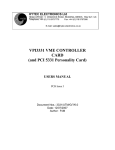
1
*****************************************
*
*
*
*
LP 1341 LIST PROCESSOR
*
*
*
*
128K OR 256K, 7 TRIGGER VERSION
*
*
*
*
TECHNICAL MANUAL
*
*
*
*
AND PROGRAMMING INSTRUCTIONS
*
*
*
*
*****************************************
HYTEC ELECTRONICS LTD.,
5 CRADOCK ROAD, READING, RG2 0JT, U.K.
Doc:
Issue:
Date:
Author:
UM1341
K
12/5/99
PJM
*
*
August 1993
ENGINEERING NOTICE
IMPORTANT ENHANCEMENTS TO LP 1341 LIST PROCESSOR
From serial number 516 onwards, the LP 1341 is constructed
using a new PCB, issue 3, which incorporates a number of
corrections and improvements. (The PCB issue number can be
found on the component side of the board, just below the
wiring for the front panel Cannon connector). The
improvements are as follows:a)
Incorrect Jump Address
It has been found that a valid slave write command to
the module can corrupt Jump Addresses. This error has
been corrected in the new artwork.
b)
Unwanted Pointer Incrementing
In earlier models, when a Jump instruction was not
obeyed, unwanted incrementing of either data pointer
could occur, depending on certain Jump Address bits.
Hardware modifications have been included to avoid this.
c)
Jump and Restore Pointer
One customer requested enhancement to the Jump
conditions has been incorporated as a standard feature.
Users at Argonne wanted a "Jump and Restore Write
Pointer" feature so that one set of 'constant' output
data could be used repeatedly for a set-up task. This
has now been included in the standard set as Jump
Condition Code 7. This is an unconditional Jump which
restores the value of the write pointer to its last
loaded value.
Existing users should find no difference in the behaviour of
the new units and field upgrade of old units is possible,
contact Hytec for details.
P Marshall - 27 August 1993.
August 1995
ENGINEERING NOTICE
FURTHER IMPORTANT ENHANCEMENTS TO LP 1341 LIST PROCESSOR
As the result of continuing improvement of Hytec's products,
another new artwork for the LP1341 has been produced, Issue 4.
The aims of this revision are as follows:a)
To incorporate minor corrections to the Issue 3 artwork,
which have no effect on the characteristics of the unit.
b)
To make two distinct changes to the design in line with
customer requests for enhancements, namely:i)
More data memory: the unit can now accept bigger memory
chips, so that it may have up to 1 megaword by 24 bits of data
memory.
ii)
Programmable self-trigger rate. The old scheme gave the
user two internal trigger frequencies selected by jumpers, which
were virtually useless. These have been deleted and replaced by
a divided crystal oscillator capable of outputting a variety of
frequencies from 0.001 Hz to 100 kHz.
The LP 1341 is still produced by Hytec using this board, with
the smaller memory chips, giving 128K or 256K words of data
memory, and without any self trigger facility.
A new unit, called the LP 1342, is now offered by Hytec, using
this board, which has larger memories of 512 or 1024K words, and
the new programmable self trigger scheme. However, the self
trigger feature makes use of the comparator register to store
the desired frequency value, which means that operationally, you
cannot use both functions, just one at a time.
This manual concerns itself ONLY with the board built as an LP
1341.
Doc:
UM1341
Issue: K
Date: 12/5/99
Page: 1/20
Author:PJM
CONTENTS
Page
Module Data Sheet
2/3
1.
Introduction
4
2.
Configuring
5
3.
Detailed Operational Description.
7
3.1
Starting
8
3.2
Stopping
9
4.
Operating Example.
12
5.
Seven Trigger Operation.
13
6.
Main Logic Sequencer.
14
7.
Handy Hints and Conditional Jumping.
15
8.
Physical and Electrical.
16
9.
Parts List.
18
Doc:
UM1341
Issue: K
Date: 12/5/99
Page: 4/20
Author:PJM
1. Introduction
This manual is really aimed at people who have already used the LP1340 List
Processor or the T7 (seven trigger) variant and are familiar with the basic
principles of operation of Auxiliary Controllers in CAMAC Crates. Those who do not
have that experience should read the data sheet and this manual very carefully
before making a start. The best way to find out how to operate this module is to
start with the example given and then progress from there. Section 7 contains a lot
of valuable information about the possible pitfalls in setting this device to work
and some more detailed information about how the hardware actually works.
Users of the LP1340/T7 will find that this unit will run the same software as that
unit, except that bits 5-8 of the LAM registers will always be read as '1' by the
commands F(1) A(12,13,14), so they should be masked off by software.
After you have studied the data sheet on the module, this manual will outline the
basic principles of operation of the unit, what options are available and how it
differs from its predecessor, the LP 1340.
The major differences between this unit and the LP 1340 are as follows:a)
Larger Memories:
Data Store is 128K x 24 bits, optionally 256K
Instruction Store is 8K x 16 bits and can be EEPROM.
Both memories are battery-backed.
b)
New Jump Instruction Format:
The new Jump Instruction Format is as follows:
|16 |15 |14 |13 |12 |11 |10 | 9 | 8 | 7 | 6 | 5 | 4 | 3 | 2 | 1 |
1
1
\ /
JUMP
JC2 JC1 JC0 A11
|
|
|
\
\
/
\/
JUMP CONDITION SPECIFIERS
A1
/
DESTINATION ADDRESS
The Jump Condition Specifiers operate as follows:JC2
JC1
JC0
0
0
0
0
1
1
1
1
0
0
1
1
0
0
1
1
0
1
0
1
0
1
0
1
ACTION
Unconditional Jump
Jump if No Q response during last CAMAC cycle
Jump if data read greater than stored value
Jump if data read less than stored value
Jump unconditionally and await trigger
Jump if No Q and await trigger
Jump if data read equal to stored value.
Jump (uncond.) and restore Write Data Pointer
Doc:
UM1341
Issue: K
Date: 12/5/99
Page: 5/20
Author:PJM
The "Stored value" referred to above means the data written into the LP 1341's
Comparator Register which can then be compared with actual Read Data obtained by the
LP 1341 during the last dataway READ command it performed.
c)
The List Processor may now read its own Instruction Pointer.
A modification has been incorporated to allow the LP1341 to read its own Instruction
Pointer so that blocks of read data from different triggers can be distinguished by
incorporating a "Read Instruction Pointer" command as the first in each list. The Q
response to F(1) A(0) has been changed to Q=1 for this command so that the data read
is retained.
d)
Multiple Trigger Inputs.
The LP 1341 has seven trigger inputs via a front panel 9-way Cannon connector,
which invoke a "bootstrap" program which results in an internal jump to the start
of the chosen list. As we shall see later, one of the triggers (Trigger 1) may be
used in the same way as the old LP1340 trigger, also, the LEMO Trigger input with
its LAM links can still be used as Trigger 7.
e)
The Control Register is NOT fitted.
This register, which used to work with the LP 1340's loop counter/comparator, is not
fitted in the LP 1341 and is replaced by a data comparator, permitting "JUMP if
Greater Than" type instructions. The "Jump and Await Trigger" function, formerly
derived from a bit in the control register, is taken over by bits in the new Jump
Instruction Format as seen above.
2. Configuring
Before the List Processor can be assembled into a CAMAC system, its operating mode
must be decided, and its internal links set accordingly. These are as follows:JP1-JP23
Links to permit the appearance of a given LAM
to start execution of a list of instructions. Note
that this is "wire ORed" with the LEMO Trigger
Input (front panel) and that use of both at the
same time is inadvisable. In the case of the
LP1341, this trigger input (and also the LAM
triggers) are wired in as TRIGGER 7. JP1
connects in LAM1 and so on. Fit only one.
Note: All triggers are level sensitive. (Sect. 5)
Standard Setting:
All OUT.
Doc:
UM1341
Issue: K
Date: 12/5/99
Page: 6/20
Author:PJM
JP24,25,26
OVERFLOW SELECT
If any of these three links is fitted, then as
soon as the TOP 8 or 16 BITS of the corresponding
pointer reaches the "all ones" state, the LP1341
will stop, setting NO X and FINISHED as it does
so. This therefore represents OVERFLOW WARNING.
See also Section 7 (b).
JP24
selects the top 8 bits of the Instruction Pointer
(Note that overflow is on all 16 bits, not just
the 13 bits of the "real" counter).
JP25
selects the Read Data Pointer (Note that
the data memory is now 128K or even 256K,
read and write data pointers are 24-bits,
only 17 or 18 bits have any real meaning.
overflow is on bits 9-24).
JP26
selects the Write Data Pointer
since
both
although
Thus
Standard Setting - All OUT
JP27/JP28
STOP/VETO
This determines the function of the Stop/Veto
input as follows:JP27 - STOP. If the front panel input is taken
low, the List Processor will stop after the
current instruction, and set FINISHED and NO Q
Status.
JP28 - VETO.
If the input is low at the time
that the LP1341 advances to the next instruction,
the relevant Data Memory Pointer will not be
incremented (data will be ignored). Clearly this
only applies if reads are being performed, and
some external module is looking at data patterns
and issuing VETO accordingly.
To be effective, the VETO input must be taken low
no more than 500nS after the beginning of the
LP1341's CAMAC Cycle, and should be held low until
the end of that CAMAC cycle.
Standard Setting - JP 27 IN.
Note that in order to satisfy a number of applications where the absence of Q means
"No Data Ready", this condition has been made an internal source of VETO (i.e.
ignore data). The effect of this will be to prevent the incrementing of pointers,
which will mean that data will simply be ignored, when performing commands in Q
Ignore Mode (either Reading or Writing), e.g. Selective Set LAM Mask, Read LAM
Status.
Doc:
UM1341
Issue: K
Date: 12/5/99
Page: 7/20
Author:PJM
If, therefore, your list will include instructions involving reading or writing
without expecting Q=1 and you want the pointer(s) to increment, please contact Hytec
for details of the required modification.
JP29
JP31
Self-Trigger Select. NOT USED. Contact Hytec for
details of use if desired.
128K/256K Memory Select.
JP31 IN - 256K Memory
JP31 OUT - 128K Memory (128K memory mapped twice
over 256K area to allow proper overflow)
JP32
JP33
JP34
3.
512K memory chip use only, do not fit.
128K memory chip use only: must be fitted.
512K memory chip use only, do not fit.
Detailed Operational Description
The List Processor LP1341 is an ACB Auxiliary Controller in accordance with EUR
6500. As such, it must reside in a CAMAC Crate, connected to an ACB Master
Controller in stations 24 and 25 by a rear-panel 40-way ACB cable and a set of
Request/Grant cables at the front. The user must connect Request to Grant In on
the highest priority controller, and then Grant Out on that controller to Grant In
on the next lowest priority device and so on. It is left to the user to decide the
order of priority of the controllers, bearing in mind their relative needs in terms
of desired operating speed and importance of controlling actions. The LP1341 is
capable of accepting and responding to ACL, but cannot generate it itself.
Having configured the LP1341, assembled the modules in the crate and connected up
the ACB etc., the user can now switch on and program the LP1341 with its list(s) of
commands and Write Data (if any) as follows:Test Booked F(27) A(0) - This tells you if the List Processor is available or not.
If you get Q, OK to proceed. The List Processor is now booked to you and will give
NOT Q to all subsequent Tests by other potential users. The LP 1341 will not GO
unless it has been BOOKED.
FROM NOW ON WE ARE GOING TO CONSIDER THE PROGRAMMING OF THE LP1341 AS A "STANDARD"
LIST PROCESSOR, FOR THE DETAILS OF HOW TO USE THE SEVEN TRIGGERS, SEE SECTION 5.
Write Instruction Pointer - F(17) A(0) - To point to the start of the list of
instructions you are going to write into the Instruction Store.
Doc:
UM1341
Issue: K
Date: 12/5/99
Page: 8/20
Author:PJM
Write Instruction Store - F(16) A(0) - Write a sequence of NAFs into the Store at
incrementing addresses (this happens automatically); not necessary, of course, if
they are already programmed in and you are just going to execute them again. Finish
with either a STOP instruction, or a JUMP instruction. Don't forget to add the Q
IGNORE bit to any command where the module in question will only give X but not Q in
valid circumstances. If you do not do this, the LP1341 will repeat the command for
about 10 uSec and then STOP, setting the NO Q status bit.
Write Instruction Pointer again, to point to List Start. Remember that for seven
trigger operation, this must be at zero since that is where the "bootstrap" jump
instructions should be loaded. For "normal" operation, with dataway GO or Trigger 1,
you can start anywhere.
Write Write-Data Pointer - F(17) A(1) - Point to the beginning of an area of data
memory into which you are going to put Write Data to be used by the LP1341 when it
executes a command involving F16 and not F8.
Write Data Memory using Write Pointer - F(16) A(1) - Writes a sequence of data words
into Memory (pointer auto-increments).
Write Write-Data Pointer again to point at the start.
Write Read-Data Pointer - F(17) A(2) - To point to the start of the area of data
memory to be used to store data read from modules during valid instructions which
had neither F16 nor F8 present AND which gave a TRUE Q Response.
Clear LAM Status Register (All bits) - F(23) A(12) - data 'F' HEX to clear the GO
bit and any other status bits set by the previous sequence.
Clear LAM Mask Register (All bits) - F(23) A(13) - data 'F' HEX again, then:
Selective Set LAM Mask Register - F(19) A(13) - using appropriate bits to allow End
status conditions to generate an Interrupt via LAM.
3.1
Starting
The List Processor is now ready to be started. In the "STANDARD" mode we are
discussing now, this can be done in two ways; either by selectively setting the GO
bit, bit 4, in the LAM Status Register (F(19) A(12)), or by Enabling Trigger F(26) A(0) and giving the module an active LOW TTL trigger pulse on TRIGGER 1
via the front panel 9-way Cannon Trigger Input socket. Note that Trigger 1 causes
the LP1341 to look at the instruction it is pointing at and if it is NOT a jump
instruction, it will start executing commands as usual. In this way it can be made
"Compatible" with existing LP1340 units. Having been placed in the "GO" condition by
either of these means, the LP1341 will start doing CAMAC cycles at high speed (about
1.5 uSec each if "unopposed") until it reaches a Stop condition.
Doc:
UM1341
Issue: K
Date: 12/5/99
Page: 9/20
Author:PJM
The command Test GO/Trig Enb.- F(27) A(1) - can be used to test whether the List
Processor is Running or Awaiting Trigger. In either case, it would be disastrous for
a computer to attempt to access the LP1341's internal registers at this time. Note
that because the List Processor runs so fast, it is quite possible that if you tell
it to GO, by setting bit 4 in the Status Register, then by the time you come back to
ask it if it is running, it will have finished!
Whilst Execution is in progress, it is in fact possible to access all the internal
registers of the LP1341 and some users successfully do this, although the data sheet
implies that this is not so. This is because some of the commands to be "excluded"
do not generate Q anyway, so that the only way to signal their nonacceptance would
be to give NO X. This is thought to be at best misleading.
Reading the LP1341's LAM Status Register whilst execution is under way will show 8
bits of data. The bottom 3 bits (the End condition bits) should all be zero; bit 4
should be a '1' if you set it to start, (this does not happen if the LP is
Triggered); bits 5 to 8 will all be read as '1' and they should be ignored.
3.2
Stopping
( See also the IMPORTANT NOTE - Page 11 ).
There are a number of ways in which execution of a list of instructions can be
terminated, as follows:Stop Instruction: An instruction was encountered with bit
The LP1341 stops, resets its internal GO flag (not the GO
Register) and sets the Finished bit (bit 3) in the Status
Pointer will be pointing to the Stop Instruction, and the
will be pointing to the location ABOVE the last one used.
16 set and bit 15 not set.
bit in the Status
Register. The Instruction
Read and Write Pointers
Overflow: When the top 16 bits of the Read or Write Pointer or the top 8 bits of
the Instruction Pointer selected by one of links 24, 25 and 26 has reached the all
'ones' state, the LP1341 will stop, reset its GO flag and set Finished and NO X. The
pointers will not be incremented following the last instruction. The LP1341 stops,
therefore, pointing to the last instruction executed and not having incremented
either of the two Data Pointers. This is true of all stop conditions from here on.
External Stop:
If JP 27 is IN and the Stop/Veto input is pulled low, then at the
end of the current instruction, the LP1341 will stop, set Finished and NO Q and
reset its GO flag.
NO X Abort:
If the LP1341 does not get an X response during a CAMAC cycle
(sampled at S1 time), it will stop, set NO X and reset its GO flag.
Doc:
UM1341
Issue: K
Date: 12/5/99
Page: 10/20
Author:PJM
Q Repeat Fail or Time-out: If the LP1341 does not get Q to a Command and the Q
Ignore bit (bit 15) is not set in the instruction, then it will repeat that
instruction until either it does get Q, or the 10 uSec timer expires. The Time-out
period is set internally by a capacitor, C5, whose standard value is 3n3. Apart from
failing to get a good Q response from a module, there is one other way in which a
Time-out can occur, which is the failure of the List Processor to gain control of
the Crate through the ACB (someone is "hogging" the bus, or a wrong connection)
within 10 uSec.
The effect of a Time-out is to stop the LP1341, which resets its GO flag and sets
the NO Q Status bit.
When the List Processor has Finished, check that the finishing conditions are
correct by reading the LAM Status Register - F(1) A(12) - then, if you wish, check
that the pointers are as expected (i.e. that the right number of cycles of each
type took place), then read out the data collected, if any. To do this, you must
obviously reset the Read Pointer to its original value - F(17) A(2) - and then read
out the data sequentially with F(0) A(2). This will auto-increment the pointer.
It is possible to read out data whilst the list processor is running by using the
Write Data Pointer, but clearly that means that you cannot do any writes with the
LP1341, and also that you must not read the data out faster than it is being
collected. Note that the act of reading this data out concurrently will reduce the
overall execution rate of the list processor because it will be sharing use of the
CAMAC Dataway with the read-out controller.
Having accomplished all this, you can either perform another sequence with the List
Processor, or un-book it so that another computer can use it if it wishes. The
command to do this is RESET - F(25) A(15) - which does the following :Reset
Reset
Reset
Reset
BOOKED Flag
all LAM Status and Mask bits
Trigger Enable, Triggered Flag and GO Flag
Main Logic Sequencer and Trigger Input Logic
Z.S2 does all the above, plus :Reset all Pointers to zero
Power-on Reset has the same effect as Z.S2.
The List Processor is now free to accept another Test Booked
Command.
Doc:
UM1341
Issue: K
Date: 12/5/99
Page: 11/20
Author:PJM
IMPORTANT NOTE: Stopping in Triggered Mode.
The GO state of the List Processor is the logical OR of the following:
a)
The output of the GO flip flop, set by a '0' to '1' transition on bit 4 of the
LAM Status Register, and
b)
The output of the "Triggered" flip flop, set by a '1' to '0' transition on a
trigger signal, if triggers are enabled.
When the List Processor's state machine detects a Stop condition, and in this case
we are thinking primarily of a "Pointer Overflow" condition, it resets both of the
above flip-flops and then sets the appropriate LAM Status Register bits to show why
it stopped.
After it has done this, and if Triggers are Enabled, the reception of another
trigger will cause the LP1341 to examine the state of the Overflow flag, and, if it
is set, it will go through the routine of stopping on overflow, that is setting the
relevant bits in the status register and resetting the GO flag.
It is recommended, therefore, that an interrupt routine written to handle "Stopped
LAMS" from an LP1341 working in triggered mode should Disable Triggers ON ENTRY to
prevent this action interfering with the unloading of the list processor.
Doc:
UM1341
Issue: K
Date: 12/5/99
Page: 12/20
Author:PJM
4. Operating Example
4.1
The following Program, written in CATY, shows a typical sequence
performed, reading data from an input module in the crate:
10
20
LP=7,1,16
MOD=8
'In Branch 7, Crate 1, stn. 16 with CCA2
'Module to be read in Stn. 8
100
110
120
130
140
150
160
170
180
190
200
210
220
230
240
250
260
270
280
290
300
310
320
330
340
350
360
370
380
390
400
410
420
430
440
450
460
470
480
F27 LP,0
'Test Booked [F(27) subaddress 0]
IF NOTQ GOTO 1000
'Not free, error
F24 LP,0
'Disable Trigger just in case
F17 LP,0,0
'Set Instruction Pointer to zero
LET X=MOD*512
'Generate NAF for N8 A0 F0
FOR I=1 TO 100
'100 cycles
F16 LP,0,X
'Write NAF [F(16) sub. 0, data X]
NEXT I
F16 LP,0,'100000
'Stop Instruction [bit 16 set]
F17 LP,0,0
'Inst Pointer to zero again
F17 LP,1,0
'Write Pointer to zero
F17 LP,2,0
'Read Pointer to zero
F17 LP,3,0
'Comp. Reg. = 0, comparator not used
F23 LP,12,15
'Reset all LAM Status bits
F23 LP,13,15
'Reset all LAM Mask bits
PRINT "LIST PROCESSOR READY TO GO, HIT RETURN"
WAIT
F19 LP,12,8
'Set GO bit
F27 LP,1
'Test GO/Enabled
IF CAMQ GOTO 280
'Still going ? Wait
F1 LP,12,X
'Fetch LAM Status
IF X=12 GOTO 330
'Status correct? Expect GO + FIN
PRINT "FINISHED STATUS WRONG, EXP 12, GOT",X
F1 LP,0,X
'Fetch Inst Pointer
IF X=100 GOTO 360
'As expected?
PRINT "EXPECTED 100 INSTRUCTIONS, GOT",X
F1 LP,1,X
'Fetch Write Pointer
IF X=0 GOTO 390
'Should be none
PRINT "EXPECTED 0 WRITES, GOT",X
F1 LP,2,X
'Fetch Read Pointer
IF X=100 GOTO 420
'Exp 100 Reads
PRINT "EXPECTED 100 READS, GOT",X
F17 LP,2,0
'Reset Read Pointer
FOR I=1 TO 100
'100 Reads
F0 LP,2,X
'Fetch Data
PRINT "DATA ELEMENT ",I,"=",X
NEXT I
F25 LP,15
'Reset, finished with Engines!
STOP
1000 PRINT "LIST PROCESSOR NOT FREE!"
1010 STOP
being
Doc:
UM1341
Issue: K
Date: 12/5/99
Page: 13/20
Author:PJM
5.
Seven Trigger Operation.
The Trigger Input connector on the front panel, a 9-way Cannon socket, pinout in
section 8, brings in seven active-low TTL trigger signals, each pulled up by an
internal 1Kohm resistor.
The trigger inputs are LEVEL sensitive and must be held low for a minimum of 300
nSec. More than one trigger may be true at a time, since they are prioritised and
latched before presentation to the Main Logic Sequencer. If one or more triggers are
present when a list completes, then the highest numerical value trigger will then be
serviced (trigger 7 is highest). The maximum delay between setting a trigger input
true and the start of list execution is just under 2 microseconds for trigger 7;
trigger 1 takes just 500 nSec. Triggers are ignored when disabled.
The trigger should be removed before the list in question completes, or it will
execute again. A different trigger MAY be present at this time, however, which will
be executed as soon as the Logic Sequencer gets back to the "reset" state.
Before any triggers can be handled (apart from the straightforward use of trigger 1
as we saw above), the Instruction store must be loaded with the "Bootstrap" Jump
Instructions and the lists themselves.
The "Bootstrap" looks like this:
Address
Contents
Function
0006H
0005H
0004H
0003H
0002H
0001H
0000H
11000xxxxxxxxxxx
11000xxxxxxxxxxx
11000xxxxxxxxxxx
11000xxxxxxxxxxx
11000xxxxxxxxxxx
11000xxxxxxxxxxx
11000xxxxxxxxxxx
Jump
Jump
Jump
Jump
Jump
Jump
Jump
to
to
to
to
to
to
to
List
List
List
List
List
List
List
7
6
5
4
3
2
1
Start
Start
Start
Start
Start
Start
Start
Where "x" is part of the 11 bit jump address, and list 1 is triggered by Trigger 1
and so on. "H" means HEXADECIMAL.
Starting from the Start Address of each list, the Instructions are then loaded,
finishing with a Jump to Zero and await trigger, which is:
16 15 14 13 12 11 10
1
1
1
0
0
0
0
9
8
7
6
5
4
3
2
1
0
0
0
0
0
0
0
0
0
Notice that bit 14 is a '1' to denote "re-trigger".
After all the lists have been loaded, the Instruction Pointer should be reset to
zero. The Read Pointer should also be reset to zero, then read data collected by
each list will accumulate upwards, tagged if needed by Reads of the LP1341's own
Instruction Pointer as mentioned above, but remember that this read will give the
top 8 bits all '1's (Bits 17 - 24) due to the internal bus pull-ups.
Doc:
UM1341
Issue: K
Date: 12/5/99
Page: 14/20
Author:PJM
If it is required that one (and only one) of the lists include writing data, then
this should be loaded into memory, preferably at the top for obvious reasons, and
the Write Pointer left pointing to it. Remember to load the "set" of write data as
many times as it will be needed, unless you use the new "Jump and Restore Write
Pointer" feature available from serial no. 516 onwards.
The way that the bootstrap works is as follows:
a)
The Main Logic Sequencer (MLS) sees the GO bit true, which
comes from either the Dataway GO or the Trigger input logic.
b)
The Trigger Input Logic will have generated a 3-bit code,
which is presented to the MLS.
c)
If the 3-bit code is greater than one, the MLS uses the code
to skip through the bootstrap program to the jump
instruction corresponding to the trigger.
d)
If the trigger code was zero or one, then the instruction
being pointed to is checked to see if it is a Jump, if not,
execution starts there and then.
e)
List execution proceeds as normal, finishing with a jump to
zero and await trigger.
6.
The MAIN LOGIC SEQUENCER
This is a PLS 105 (formerly 82S105) Programmable Logic Sequencer, which is clocked
by the 10M signal, the output of the 10 MHz oscillator. This also clocks the CAMAC
Cycle Generator. The Main Logic Sequencer's inputs and outputs are as follows:NAME
PIN NO.
FUNCTION
INPUTS
CAT
/OVF link
STOP
ERR
/TIMEOUT
CJNQ
/TCODE1
/TCODE2
GO
B16
B15
/LOOPEND
CQSTAT
XSTAT
BUSYFF
/TCODE4
2
3
4
5
6
7
8
9
20
21
22
23
24
25
26
27
Await Trigger (stop) after Jump (conditioned)
Pointer Overflow flag input
Ext. STOP Input
Overall 'OR' of possible ERRORS
Timer Expired
Jump if No Q Response (conditioned)
Trigger Code, Binary value 1
Trigger Code, Binary value 2
Start doing Instructions
STOP or JUMP Instruction
JUMP Instruction or Q Ignore
Done all Loops (NOT USED)
Q State This Instruction (conditioned)
X State This Instruction
CAMAC Cycle started OK
Trigger Code, Binary value 4
Doc:
UM1341
Issue: K
Date: 12/5/99
Page: 15/20
Author:PJM
OUTPUTS
CKINST
FINISH
NO X
NO Q
START
JUMP
SJUMP
RGO
10
11
12
13
15
16
17
18
Advance Pointer(s)
Set FINISHED LAM Status
Set
NO X
LAM Status
Set
NO Q
LAM Status
Do a CAMAC Cycle
Ready to load Jump Address
Load Jump Address
Reset Internal GO Flags
"Conditioned" means that the signal has been processed by the Jump Logic PAL, IC44,
which looks at the Jump Condition Specifiers and the outputs of the comparator to
decide whether to jump or not (see below).
7. Handy Hints and Conditional Jumping
a)
Always remember to read the LAM Status Register after stopping, especially if
things did not go as planned. Look at the STOP condition table on the data sheet to
see what happened and look at the Instruction Pointer as well. Check that you have
composed the Instructions properly, with bits 1-5 = Function Code, bits 6-9 are
Subaddress, and bits 10-14 are Station Number and bit 15 is Q-Ignore. Thus :
INST = F + (A*32) + (N*512)
[ + 16384 if Q-ignore]
b)
When using pointer overflow to stop the List Processor, remember that the
physical pointers are all a lot wider than they need to be, that is you only need 18
bits to address the 256K words of the data memory, but there is a 24-bit pointer.
The top 6 bits do nothing and the memory just wraps round if you count past the 18
bit boundary, but for overflow, the top 6 bits are considered and MUST be '1'. So on
a unit with 256K words, the top address is HEX 03FFFF and address 040000 is the same
as address 000000. Overflow is on the top 16 bits of the read/write data pointers,
so for these pointers this is HEX FFFF00, which is at 256K-255 words (ignoring the
top 6 bits) and for the instruction pointer (overflow on top 8 bits) it is HEX FF00
(64K-255). If you wish to reach overflow after a certain number of cycles, just
take that number away from the overflow value and start at that address. For
example, to stop after 200,000 reads, install JP25 and start the Read Data Pointer
F(17) A(2) at HEX FFFF00 - 30D40 (200,000 in HEX) which is HEX FCF1C0. Users of 128K
LP 1341s will have JP31 removed so that their memory is duplicated over the top
and bottom halves of the area, so they will set their start address to somewhere
above the 128K boundary in the last 256K page.
Doc:
UM1341
Issue: K
Date: 12/5/99
Page: 16/20
Author:PJM
On the subject of pointers and addressing, remember that the instruction store is 8K
words, but jump addresses are still restricted to the bottom 2K of that store
because there are only 11 address bits in the jump instruction. Thus if you wish to
return to the start of a list of commands, this must be below the 2K boundary.
On the front panel there are 5 LEDs, one for 'N', stretched to 10mSec., one for
'RUN' or GO, which comes on when the LP1341 is executing a list, and three showing
which trigger is active.
These Trigger Code LEDs come on when a non-zero trigger is received and will go off
when the list is completed.
If a trigger is received when triggers are not enabled, it will simply be ignored.
(Early units of this type did not do this).
8. Physical and Electrical
The module is a single width CAMAC unit, with rear mounted 40-way ACB header, front
panel 9-way Cannon socket Trigger Input connector, six LEMO sockets and five LEDs.
Doc:
UM1341
Issue: K
Date: 12/5/99
Page: 17/20
Author:PJM
POWER CONSUMPTION
Basic Module
2300 mA Typ.
256K Memory option
+100 mA
Note: Due to the high power consumption of this module, we recommend that forced
air cooling be used.
SIGNAL STANDARDS
All inputs and outputs are at standard TTL signal levels, all open-collector.
CONNECTOR PINOUTS
Rear ACB Connector - 40 way header, pin 1 bottom right
40
38
36
34
32
30
28
26
24
22
20
18
16
14
12
10
08
06
04
02
AL23
AL21
AL19
AL17
AL15
AL13
AL11
AL09
AL07
AL05
AL03
AL01
Request Inhibit
Request
ACL
EN16
EN 4
EN 1
39
37
35
33
31
29
27
25
23
21
19
17
15
13
11
09
07
05
03
01
AL22
AL20
AL18
AL16
AL14
AL12
AL10
AL08
AL06
AL04
AL02
GND
GND
GND
GND
GND
EN 8
EN 2
GND
All signals on the ACB are ACTIVE LOW
Trigger Input Connector - 9-way Cannon Socket.
Pin
Function
1
2
3
4
5
6
7
9
Trigger
Trigger
Trigger
Trigger
Trigger
Trigger
Trigger
GROUND.
Input
Input
Input
Input
Input
Input
Input
1
2
3
4
5
6
7
("Standard" Trigger)
Doc:
Issue:
Date:
Page:
Author:
Parts list for :- LP1341 ISSUE 4
Part
Type
Outline
IC1
74622,74LS622
DIL20
IC2
74622,74LS622
DIL20
IC3
74622,74LS622
DIL20
IC4
74642,LS642-1
DIL20
IC5
74642,LS642-1
DIL20
IC6
74642,LS642-1
DIL20
IC7
74652,LS652
DIL24.3
IC8
74652,LS652
DIL24.3
IC9
7405,7405
DIL14
IC10
PLS100,PLS100 "1341P10" DIL28
IC11
74245,HCT245
DIL20
IC12
74245,HCT245
DIL20
IC13
74245,HCT245
DIL20
IC14
74682,LS682
DIL20
IC15
74682,LS682
DIL20
IC16
PAL22V10, "1341P16V"
DIL24.3
IC17
PAL22V10, "1341P17V"
DIL24.3
IC18
PAL22V10, "1341P18V"
DIL24.3
IC19
74593,LS593
DIL20
IC20
74593,LS593
DIL20
IC21
74593,LS593
DIL20
IC22
74245,HCT245
DIL20
IC23
74245,HCT245
DIL20
IC24
74593,LS593
DIL20
IC25
74593,LS593
DIL20
IC26
74593,LS593
DIL20
IC27
74245,HCT245
DIL20
IC28
74245,HCT245
DIL20
IC29
7414,74LS14
DIL14
IC30
7475,74LS75
DIL16
IC31
7408,74LS08
DIL14
IC32
628128,628128
DIL32
IC33
628128,628128
DIL32
IC34
628128,628128
DIL32
IC35
74593,LS593
DIL20
IC36
74593,LS593
DIL20
IC37
7474,74LS74
DIL14
IC38
7404,74LS04
DIL14
IC39
7404,74LS04
DIL14
IC40
74374,HCT374
DIL20
IC41
74374,HCT374
DIL20
IC42
74622,ALS622
DIL20
IC43
74622,ALS622
DIL20
IC44
PAL22V10,"1341P44V"
DIL24.3
IC45
628128,628128 ***
DIL32
IC46
628128,628128 ***
DIL32
IC47
628128,628128 ***
DIL32
IC48
6264,6264
DIL28
IC49
6264,6264
DIL28
IC50
PLS105, "BRAINV9F"
DIL28
***
256K Memory only
Manufacturer
UM1341
K
12/5/99
18/20
PJM
Doc:
Issue:
Date:
Page:
Author:
Parts list for :- LP1341 ISSUE 4
Part
Type
IC51
IC52
IC53
IC54
IC55
IC56
IC57
IC58
IC59
IC60
IC61
IC62
IC63
IC64
IC65
IC66
IC67
IC68
IC69
IC70
D1
D2
D3
D5
D6
D7
D8
D9
D10
D11
D12
XT1
R1
R2
R3
R8
R9
R10
R11
R12
R13
R14
R15
R16
R17
R18
C1
C2
C3
74174,74LS174
75452,75452
PLS100, "1341P53"
7475,74LS75
7408,74LS08
7408,74LS08
7405,7405
7430,74LS30
PAL18P8,"LPPALV3"
PAL18P8,"LPPALV3"
PAL16V8,"LPTRIG2C"
74374,LS374
Not fitted
Not fitted
74132,74S132
7474,74LS74
7400,74LS00
74123,74LS123
7432,74LS32
Not fitted
1N5401,1N5401
1N4148,1N4148
1N4001,1N4001
1N4148,1N4148
1N4148,1N4148
1N4148,1N4148
1N4148,1N4148
1N4148,1N4148
1N4148,1N4148
1N4148,1N4148
1N4148,1N4148
HC18S,10MHz
RESA8,3K3
RESA8,2K2
RESA8,100K
RESA8,560R
RESA8,10K
RESA8,10K
RESA8,10K
RESA8,1K0
RESA8,680R
RESA8,100K
RESA8,100K
RESA8,10K
RESA8,1K0
RESA8,3K9
CAPR4D4E,47U/16V
CAPR4D4E,47U/16V
CAPR4D4E,10uF16V
Outline
DIL16
DIL8
DIL28
DIL16
DIL14
DIL14
DIL14
DIL14
DIL20
DIL20
DIL20
DIL20
DIL14
DIL14
DIL14
DIL16
DIL14
DDCMC
DO35
DO41
DO35
DO35
DO35
DO35
DO35
DO35
DO35
DO35
HC18U
RESA8
RESA8
RESA8
RESA8
RESA8
RESA8
RESA8
RESA8
RESA8
RESA8
RESA8
RESA8
RESA8
RESA8
CAPR4D4E
CAPR4D4E
CAPR4D4E
Manufacturer
UM1341
K
12/5/99
19/20
PJM
Doc:
Issue:
Date:
Page:
Author:
Parts list for :- LP1341 ISSUE 4
Part
Type
C4
CAPR2W2,56pf
C5
CAPR2W2,3N3
C6-C36 inc.
100nF CER.
C37
CAPR2W2,56pf
C38
CAPR2W2,470pF
C41
CAPR2W2,1n0
C42
CAPR2W2,2n2
RN1
RN8COM,1K
RN2
RN8COM,10K
RN3
RN8COM,10K
RN4
RN8COM,1K
RN5
RN8COM,470R
CO1
PL40-01,IDC40
CO2
SK9D,D9SK
FS1
FUSECMC,3A
BT1
Not fitted
JP1-34 JUMPER,JP
LD1
LEDT5MM,N
LD2
LEDT5MM,RUN
LD3
LEDT5MM,TRIG CODE 4
LD4
LEDT5MM,TRIG CODE 2
LD5
LEDT5MM,TRIG CODE 1
LM1
LMSP,TRIGGER IN
LM2
LMSP,FINISHED OUT
LM3
LMSP,STOP/VETO
LM4
LMSP,REQUEST
LM5
LMSP,GRANT-IN
LM6
LMSP,GRANT-OUT
Outline
Manufacturer
CAPR2W2
CAPR2W2
CAPR2W2
CAPR2W2
CAPR2W2
CAPR2W2
CAPR2W2
SIL9
SIL9
SIL9
SIL9
SIL9
ACB
9WCANBD
FUSECMC
JP
LED5H
LED5H
LED5H
LED5H
LED5H
LMSP
LMSP
LMSP
LMSP
LMSP
LMSP
RED
GREEN
RED
RED
RED
UM1341
K
12/5/99
20/20
PJM