1
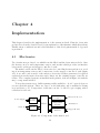
Comparator
Set Point
+
Heater
-
Temperature
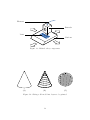
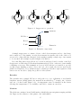
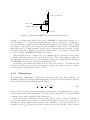
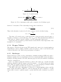
Figure 4.13: PID heater controller schematic
account such behaviours. PID controllers are widely used where a process which is not
completely understood must be controlled [Ben93].
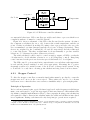
Figure 4.13 shows a schematic of the PID controller used in the system. At time t
the comparator calculates the error, e(t), between the actual temperature and the set
point. A value is calculated from this error using a factor proportional to the error, the
error accumulated over time (integral) and the error’s rate of change (derivative). These
factors are weighted by the constants Kp , Ki and Kd respectively and the result used
to control the heater. The three weights must be chosen manually to produce sensible
behaviour. §5.5 discusses how these values were selected.
The value calculated could be used to control an analog output or PWM1 or a threshold value used to decide whether a heater is on or off (‘bang-bang’ control). Bang-bang
control was used as the previous electronics proved this method to be adequate.
The PID control loop is executed in its own task twice a second when each temperature
is read and the heaters switched on and off as appropriate. Executing the loop more
frequently would not be useful because of the slow rate of change in the system. Doing
so would also be costly due to floating point calculations being carried out in software.
4.2.3
Stepper Control
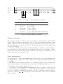
To drive the stepper controllers, accurately timed pulses must be produced to cause the
stepper motors to move at the correct speed. These pulses also need to be coherent
between motors so that the three axes can move simultaneously to plot straight paths.
Principle of Operation
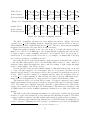
Before each movement begins, a periodic timer is set based on the frequency at which steps
must occur and is used to toggle the step signal. This is used instead of Bresenham’s line
algorithm to simplify implementation [Bre65]. Since expensive floating point calculations
are required for value conversion into machine units, the additional calculation introduced
is not significant. During each timer tick only cheap integer operations are required.
1
Pulse width modulation (PWM) is a method of approximating analog outputs by rapidly switching
a signal on and off with a varying duty-cycle. This is cheap to implement in hardware and avoids
inefficiencies in MOSFETs when only partially driven.
33