1
5.2
5.3
5.4
5.5
5.6
5.7
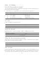
Exponential back-off by computer when µIP flow-control used . . . . . .
Checking platform temperatures using an infra-red thermometer . . . . .
Synthetic 3D printer tests for basic calibration . . . . . . . . . . . . . . .
Bad print of the test in figure 5.4(D) . . . . . . . . . . . . . . . . . . . .
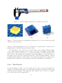
Digital callipers being used to measure test cuboids . . . . . . . . . . . .
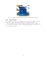
Test cuboid model (A) print from Skeinforge G-code before raft removal
(B) and after raft removal (C) . . . . . . . . . . . . . . . . . . . . . . . .
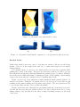
5.8 3D printed vase with detailed corners . . . . . . . . . . . . . . . . . . . .
5.9 3D printed Z-axis handle comparison . . . . . . . . . . . . . . . . . . . .
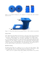
5.10 3D printed herringbone gear comparison . . . . . . . . . . . . . . . . . .
5.11 Failed large print showing warping (A) and a collision with the extruder (B)
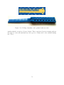
5.12 Folding ‘butterfly comb’, printed without a raft . . . . . . . . . . . . . .
53
54
54
55
55
56
A.1
A.2
A.3
A.4
A.5
A.6
A.7
A.8
A.9
.
.
.
.
.
.
.
.
.
65
66
66
67
68
68
69
69
70
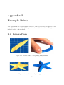
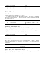
Flexible snake to test printing many thin fins . . . . . . . . . . . . . . . .
Starfish to test layering appearance . . . . . . . . . . . . . . . . . . . . .
Doorstop to test large, smooth gradients . . . . . . . . . . . . . . . . . .
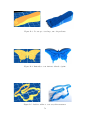
Butterfly to test intricate islands of print . . . . . . . . . . . . . . . . . .
Rabbit outline to test very thin structures . . . . . . . . . . . . . . . . .
Letter ‘A’ to test simple large shapes . . . . . . . . . . . . . . . . . . . .
Phone stand to test steep gradients . . . . . . . . . . . . . . . . . . . . .
Tooth to test large models with large overhanging areas . . . . . . . . . .
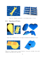
Multiple ‘metabricks’ to test building batches of objects . . . . . . . . . .
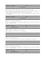
Twistable heart to test simple mechanisms and multi-part objects . . . .
Whistle (with pea printed inside) to test precise, air-tight objects with
simultaneously printed sub-components . . . . . . . . . . . . . . . . . . .
B.12 Tweezers to test flexible designs (frequently used to remove excess extrusion produced during self-cleaning) . . . . . . . . . . . . . . . . . . . . .
71
71
72
72
72
73
73
73
74
74
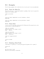
OpenSCAD showing a cube model compiled and rendered . .
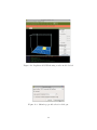
ReplicatorG GUI showing a cube model loaded . . . . . . . .
Skeinforge profile selection dialogue . . . . . . . . . . . . . . .
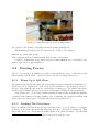
Extruder placed in the homing bracket . . . . . . . . . . . . .
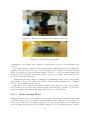
Extruder extruding plastic during a self-clean . . . . . . . . .
First layer being printed . . . . . . . . . . . . . . . . . . . . .
Fill pattern being printed . . . . . . . . . . . . . . . . . . . .
Finished cuboid being ejected . . . . . . . . . . . . . . . . . .
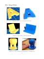
Strings of plastic left during printing requiring manual removal
.
.
.
.
.
.
.
.
.
.
.
.
.
.
.
.
.
.
.
.
.
.
.
.
.
.
.
.
.
.
.
.
.
.
.
.
.
.
.
.
.
.
.
.
.
B.1
B.2
B.3
B.4
B.5
B.6
B.7
B.8
B.9
B.10
B.11
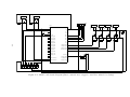
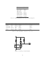
C.1 Main board circuit diagram (direct connections to stepper controllers omitted for clarity) . . . . . . . . . . . . . . . . . . . . . . . . . . . . . . . . .
C.2 End-stop circuit schematic . . . . . . . . . . . . . . . . . . . . . . . . . .
8
47
48
52
52
53
74
75
78
80