1
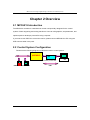
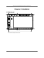
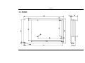
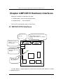
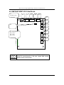
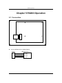
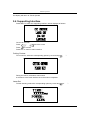
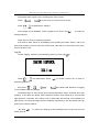
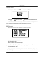
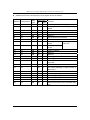
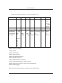
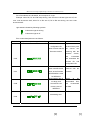
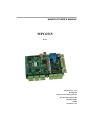
MANUFACTURER’S MANUAL
MPC6515
V 2.0
Step-Servo Co., Ltd.
Building 8-B
Dayi Zone of Incubating Hi-Tech
No.1 South 2nd Keyuan Rd
Chengdu 610041
CHINA
www.leetro.com
Copyright
The content of this manual has been carefully prepared and is believed to be
accurate, but no responsibility is assumed for inaccuracies.
Step-Servo Co., Ltd. reserves the right to make changes without further notice to
any products herein to improve reliability, function or design. Step-Servo Co., Ltd.
does not assume any liability arising out of the application or use of any product
or circuit described herein; neither does it convey any license under its patent
rights of others. Step-Servo and Leetro™are trademark of Step-Servo Co., Ltd.
Step-Servo Co., Ltd.’s general policy does not recommend the use of its products
in life support or aircraft applications wherein a failure or malfunction of the
product may directly threaten life or injury. Per Step-Servo Co., Ltd.’s terms and
conditions of sales, the user of Step-Servo Co., Ltd. products in life support or
aircraft applications assumes all risks of such use and indemnifies Step-Servo
Co., Ltd. against all damages.
Step-Servo Co., Ltd.
Customers outside China, please email to: [email protected]
©2005 by Step-Servo Co., Ltd. All Rights Reserved
II
MPC6515 Laser Engraving&Cutting Controller-User Manual (V 2.0)
Table of Content
CHAPTER 1 PREFACE....................................................................1
CHAPTER 2 OVERVIEW .................................................................2
2.1
2.2
2.3
MPC6515 INTRODUCTION ..................................................................................... 2
CONTROL SYSTEM CONFIGURATION ...................................................................... 2
MPC6515 PACK LIST ............................................................................................. 3
CHAPTER 3 INTALLATION.............................................................4
3.1
3.2
MAINBOARD .......................................................................................................... 4
PAD03 ................................................................................................................... 5
CHAPTER 4 MPC6515 HARDWARE INTERFACES ..................6
4.1
4.2
MPC6515/CPU INTERFACES ................................................................................. 6
MPC6515/MC V2.0 INTERFACES .......................................................................... 8
CHAPTER 5 PAD03 OPERATION................................................11
5.1
5.2
5.3
5.4
CONNECTION ........................................................................................................11
START SYSTEM ..................................................................................................... 12
MAIN INTERFACE ................................................................................................. 12
SUPPORTING INTERFACE ...................................................................................... 15
Cutting Contour........................................................................................................................... 15
Laser Set ..................................................................................................................................... 15
Jog Set ......................................................................................................................................... 16
Language Options ...................................................................................................................... 17
5.5
5.6
PROCESS .............................................................................................................. 17
DOWNLOAD WITH USB FLASH DISK .................................................................... 19
CHAPTER 6 HMI DEVELOPMENT..............................................20
6.1
6.2
6.3
PROTOCOL AND SYSTEM SETTING ........................................................................ 20
ADDRESS.............................................................................................................. 20
SAMPLE PROGRAM ............................................................................................... 24
CHAPTER 7 DOWNLOAD DOCUMENT.....................................25
7.1
7.2
UPDATE FIRMWARE .............................................................................................. 25
DOWNLOAD DATA ................................................................................................ 26
CHAPTER 8 ERROR CODE..........................................................27
8.1
8.2
INDICATOR LIGHT DESCRIPTION........................................................................... 27
ERROR CODE DESCRIPTION.................................................................................. 27
CHAPTER 9 FAQ ............................................................................31
9.1
EXTERNAL INDICATOR LIGHT OF U DISK ............................................................. 31
Functionality ................................................................................................................................ 31
Instruction .................................................................................................................................... 31
III
MPC6515 Laser Engraving&Cutting Controller-User Manual (V2.0)
9.2
CUSTOMIZE PAD03 CONTROL PANEL .................................................................. 31
Functionality ................................................................................................................................ 31
9.3
EXTERNAL INDICATOR LIGHT OF PROCESSING STATUS......................................... 32
Functionality ................................................................................................................................ 32
Instruction .................................................................................................................................... 32
9.4
BLOW-OFF ............................................................................................................ 32
Functionality ................................................................................................................................ 32
Instruction .................................................................................................................................... 32
9.5
GRADE ENGRAVE ................................................................................................. 33
Functionality ................................................................................................................................ 33
Instruction .................................................................................................................................... 33
9.6
SOFTWARE LIMIT UNDER IMMEDIATE MODE ........................................................ 33
Functionality ................................................................................................................................ 33
Instruction .................................................................................................................................... 33
9.7
CONTROL TWO LASER HEADS ............................................................................. 33
Functionality ................................................................................................................................ 33
Instruction .................................................................................................................................... 33
IV
Preface
Chapter 1 Preface
Thank you for using Step-Servo’s Leetro™ motion controllers. MPC6515, specially
designed for laser engraving and cutting system.
This manual will instruct you on using MPC6515 in details.
Please read the instructions carefully before using MPC6515.
Warning
User should debug the system with full consideration on
protection measures to avoid any machine damage or
human injury
Do not connect or use the Products without understanding
this manual.
Prohibited
Do not disassemble, modify nor repair the Products
without being authorized.
Prohibited
Do not subject the Product to water, corrosive or flammable
gases, and combustibles.
Prohibited
1
MPC6515 Laser Engraving&Cutting Controller-User Manual (V2.0)
Chapter 2 Overview
2.1 MPC6515 Introduction
The MPC6515 controller is a stand-alone control card specially designed for the control
system of laser engraving and cutting machines. User can edit graphics, set parameters, and
optimize path to develop a process file using computer.
If you want to use DSP5.0 to control the motion, please connect MPC6515 to PC using the
USB connect cable in the pack.
2.2 Control System Configuration
Please see the following diagram on MPC6515 motion control system:
MPC6515
USB flash
disk
PC
Transfer process data
PAD03 or
USB
Touch Screen
2
Overview
2.3 MPC6515 Pack List
No.
1
ITEM
MPC6515
QTY
Description
Type
1
Standard
Control Card
2
256M USB Flash
1
Disk
Used to upgrade firmware
and
download
data
Standard
to
MPC6515/CPU
3
USB-AA-1.5M
1
Connect cable of USB flash
Standard
disk (Length:1.5M)
4
USB-AB-3M
1
Used to connect PC to
MPC6515/CPU
Standard
(Length:
3M)
5
C4-PAD03-1.5M
1
Used to connect PAD03 to
Standard
MPC6515/CPU
6
PAD03-E
1
Human-Machine Interface
Standard
7
USB
1
Key
Standard
Softdog(Red)
of
control
Lasercut5.0.
software
To
make
installed Lasercut5.0 active
to use, please insert softdog
to the USB interface of PC
8
Software CD
1
Lasercut5.0,
MPC6515
driver
3
Standard
Remark
MPC6515 Laser Engraving&Cutting Controller-User Manual (V2.0)
Chapter 3 Intallation
3.1 Mainboard
102
Φ3×6
62
142
The mainboard adopts 6 bolts of M3
4
Intallation
3.2 PAD03
5
MPC6515 Laser Engraving&Cutting Controller-User Manual (V2.0)
Chapter 4 MPC6515 Hardware Interfaces
MPC6515 controller is composed of two parts:
1)MPC6515/MC motion control daughter board
2)MPC6515/CPU
CPU mainboard
User can find corresponding mark on each board
4.1 MPC6515/CPU Interfaces
J3
No Use
J2
Human-Machine Interface
Support HMI based on
Protocol
Modbus
USB slave interface
Connect to PC to
download data
USB
USB
Main USB interface
Download data from
flash disk
D1
Indicate light for
data downloading
and operating
J2: HMI(RS232)-support HMIs such as EasyView, BYDseries HMI, PAD03, etc. based
on Modbus Protocol
6
MPC6515 Hardware Interfaces
J2 adopts DB9-pin plug. Pin2, Pin3, Pin5 and Pin9 are used.
Pins
1
2
3
4
5
6
7
Description
TXD
RXD
GND
z Wiring of J2 and EasyView RS232 (PLC):
EasyView
(PLC)
2
3
5
MPC6515/J2
2
3
5
z Wiring of J2 and PAD03 RS232:
PAD03
MPC6515/J2
2
3
5
9
2
3
5
9
z Wiring of J2 and BYDseries HMI RS232 (PLC):
BYDseries HMI (PLC)
2
3
5
MPC6515/J2
2
3
5
7
8
9
+5V
MPC6515 Laser Engraving&Cutting Controller-User Manual (V2.0)
4.2 MPC6515/MC V2.0 Interfaces
X1
24VDC Power
JP4
X2
Y1
JP3
Y2
Y3
Y4
JP2
Y5
JP1
D1: Working Status
D2: Z-axis
D3: Y-axis
D4: X-axis
X3
X4
X5
D8
D7
D6
D5
D4
D3
D2
D1
Caution
Please pay attention to the version of MPC6515/MC. If the
version of circuit board is V1.0, user cannot find version
number in the circuit board.
8
MPC6515 Hardware Interfaces
Pin Array
1
X1
X2
2
3
4
24V
24V GND
Foot Switch
Uncapping
protection
Reserve
5V/24V
GND
5
5V/24V
Z-axis
Forward
Limit
Y-axis
Forward
Limit
X-axis
Forward
Limit
Z-axis
Reverse Limit
Z-axis
Origin
5V/24V
GND
5V/24V
Y-axis
Reverse Limit
Y-axis
Origin
5V/24V
GND
5V/24V
X-axis
Reverse Limit
X-axis
Origin
5V/24V
GND
5V/24V
Y1
Blow-off
Processing
Finished
Reserve
5V/24V
GND
Y2
Laser Power
GND
Y3
Z-axis Pulse
Y4
Y-axis Pulse
Y5
X-axis Pulse
X3
X4
X5
Analog
Output
Z-axis
Direction
Y-axis
Direction
X-axis
Direction
USB Flash
Disk
Indication
Laser
Power
6
5V/24V
Laser
On/Off
5V GND
5V
5V GND
5V
5V GND
5V
X1: Input power interface (24VDC)
Note: MPC6515 adopts single 24VDC power supply. The other power pins are output
MPC6515 adopts single 24VDC. User must use proper and
reliable power supply. Exorbitant voltage could result in
damage of components, while low voltage could result in
Warning
problem in operation.
power of the controller.
The output power of the above pins should be used only for
the common-anode and common-cathode of control signals,
and should not be used as the power supply for motor
Prohibited drives. Failure to observe this instruction could result in
damage of the controller
JP1:
Note: JP1 is related with X3, X4 and X5. If 24V voltage is required for input signal ports
X3, X4 and X5, the jumper should be connected to Pin1 and Pin2. If 5V voltage is required,
the jumper should be connected to Pin2 and Pin3. If the jumper is removed, Pin5 of X3, X4
and X5 not connected.
JP2:
9
MPC6515 Laser Engraving&Cutting Controller-User Manual (V2.0)
Note: JP2 is related with Y2. For analog-control laser power, remove the jumper,connect
laser power to Pin2. For PWM-control laser power, connect the power to Pin3.
JP3:
Note: JP3 is related with Y1. If output Y1 to drive a 24V relay, the jumper should be
connected to Pin1 and Pin2. To drive a 5V relay, the jumper should be connected to Pin2
and Pin3. If the jumper is removed, Pin6 of Y1 not connected.
JP4:
Note: JP4 is related with X2. If 24V is required for the general input X2, the jumper
should be connected to Pin1 and Pin2. If 5V voltage is required, the jumper should be
connected to Pin2 and Pin3. If the jumper is removed, Pin5 of X2 not connected.
Warning
Pin 3 and Pin4 of Y3, Y4, and Y5 is output 5V power of
MPC6515, can be the common anode for motor drive. Do
not connect external 5V to Pin3 and Pin4.
All inputs and outputs are single-ended
Caution
GND of laser power should be connected to Pin1 of Y2,
Common-ground.
Caution
10
PAD03 Operation
Chapter 5 PAD03 Operation
5.1 Connection
5
4
3
2
1
z Connect MPC6515/J2 to PAD03 RS232:
PAD03
5
4
1
2
MPC6515/J2
2 TXD
3 RXD
5 GND
9 +5V
11
MPC6515 Laser Engraving&Cutting Controller-User Manual (V2.0)
5.2 Start System
When system started, it is displayed as follows:
V3.0.0 is the version number of PAD.
5.3 Main Interface
If there’s no communication problem with MPC6515, main interface will be shown as follows:
User can set parameters according to the following parameter descriptions:
File: processing file name
Speed: percentage of the processing speed
Power: percentage of processing power. The first one is the power corresponding to low
speed, while the latter one is the power corresponding to high speed.
Pieces: repeat times of a processing file
Cursor appears at this time
Then
Press“
Press “
”“
”“
”to move the cursor to select the option you want to modify;
”to set the values of selected option, including processing speed,
12
PAD03 Operation
power corresponding to low speed, power corresponding to high speed and pieces,
stepping=1;
Press“
”“
”to select a file. If there’s no file in controller, no name of file will be
shown.
To delete a file: Press DELÆ Enter
To process a file: Press”Start/Pause”
Note:
User should press “
By using “
”to confirm the settings on speed, power and pieces.
” to confirm the settings, these parameters will not be lost even the
power goes off.
Press”Esc”, cursor will disappear
Then
Press“
For
Press“
”“
”“
point-to-point
”“
”“
”“
”to move the laser head.
beaming,
”“
hold
down
“Shoot”
button,
and
”
Press “Shoot” to beam according to the settings of Shooting;
Press ”Reset”, then X-axis and Y-axis make homing motion simultaneously;
X and Y axes will not stop until they reach their origin point respectively or until the user
press ” Stop” to stop the motion.
13
MPC6515 Laser Engraving&Cutting Controller-User Manual (V2.0)
Press”Test” to make contouring motion:
Press “
“ to return to the main interface
Jogging and reset of Z-axis
Press button “Z”, interface displays as follows
Press “
”“
” to start Z-axis jogging;
Press”Reset” to start Z-axis homing motion.
Press”Stop” to stop Z-axis homing motion;
Other buttons will not work at this time.
Press”Z” to return to the main interface;
When Z-axis is making homing motion, interface displays as follows:
This motion will not stop until Z-axis reaches the origin, or until user press “Stop ”. Then
14
PAD03 Operation
the display will return to Z-Axis Operate
5.4 Supporting Interface
Press”Menu” to enter the supporting interface, which displays as follows:
Cursor can be seen
Press“
Press“
”“
“ to move the cursor
”to confirm
Press”Esc” to return to main interface
Cutting Contour
To cut contour, select the corresponding option by cursor and press“
”:
During the motion, all buttons cannot work
It will return to the main interface once the motion completed
Laser Set
To start shooting, select the corresponding option by cursor and press“
15
”:
MPC6515 Laser Engraving&Cutting Controller-User Manual (V2.0)
The default value of time is 0 ms, default power value is100%;
Press “
Press“
”“
”“
”to move the cursor to choose Time or Power;
”to set parameters, setting=1;
Time ranged from 0-99999ms, Power ranged from 0-100%. Press”
“ to make the
settings effective.
Press “Esc” to return to supporting interface
If the time=0, laser will be on immediately upon pressing the button “Shoot”, and be off
when stop pressing. If time is set to be a fixed value, laser will be on and off for each press.
Unit for the time is ms.
Jog Set
To start Jogging, select the corresponding option by cursor and press“
Press”
”“
”to set parameters. Press “
”:
” to confirm. Press “Esc” to return to
supporting interface.
Then press ”
”“
”“
”“
” to move the laser head. Distance of Jogging
is in accordance with the settings.
The default value =0, start moving upon pressing the button “Shoot”, and stop when stop
pressing. If hold down the button, keep continuous motion at low speed for 2 seconds and
high speed for 2 seconds. If the value is not 0, laser head start moving a fixed distance at
high speed. Low speed and high speed correspond respectively to the low speed and high
speed set in machine options.
By using “
” to confirm the settings, these parameters will not be lost even the
power goes off.
16
PAD03 Operation
Language Options
Move cursor to Language and press “
Press“
”“
”
”to move cursor, press “
to choose a language:
“ to choose a preferred display language
If without pressing button to set a language, system will choose the language where the
cursor is and return to the supporting interface automatically in 30 seconds.
5.5 Process
Return to main interface, press “Start/Pause” to start the processing:
Parameter descriptions are as follows:
File: processing file name
Speed: percentage of the processing speed
Power: percentage of processing power. The first one is the power corresponding to low
speed, while the latter one is the power corresponding to high speed.
Time: processing time spent
During the process, only following buttons can work-- “Start/Pause”, “Stop”, “Up”,
“Down”,”Left”,”Right;
17
MPC6515 Laser Engraving&Cutting Controller-User Manual (V2.0)
Buttons “Up” and “Down” are used to set the processing speed. Stepping=1. The value
ranged from 0-100;
Buttons “Left” and “Right” are used to set the power corresponding to high speed.
Stepping=1. The value ranged from 0-100;
Press “Start/Pause” for odd times, it will enter pause interface and show as follows:
In this interface, only “Start/Pause” and “Stop” buttons can work;
Press “Start/Pause” for even times during processing, it will return from pause interface
to process interface.
Press “Stop ” during the process, it will stop and show as follows:
In this interface, only “Start/Pause”, “Esc, “Up”, “Down”, “Left” and “Right” buttons can
work.
Press “Start/pause” to enter process interface;
Press”Esc” to enter main interface;
Press “Up”, “Down”, “Left” and “Right” buttons to make jogging motion according to the
set parameters.
When processing completes, only “Start/Pause” and “Esc” buttons can work.
Press “Start/Pause” to enter the processing interface;
Press “Esc” to return to main interface.
18
PAD03 Operation
5.6 Download with USB Flash Disk
When a USB flash disk is plugged into the controller, main interface will show as follows:
Controller starts downloading the process files once the USB flash disk is detected.
Interface displays as follows:
Once the downloading completes, the Buzzer starts ringing, and the interface displays
as follows:
Remove the USB flash disk, and the Buzzer will cease from ringing.
Caution
USB flash disk should be formatted to FAT16, if fail to
follow this instruction, the flash disk cannot be detected by
the controller
19
MPC6515 Laser Engraving&Cutting Controller-User Manual (V2.0)
Chapter 6 HMI Development
All HMI support Modbus Protocol can be developed to control panel of MPC6515.Take
MT506LV45WV as an example:
6.1 Protocol and System Setting
Standard Modbus Protocol
PLC Type: Modbus RTU
Baud rate: 9600bps
Data bit: 8-bit;
Stop bit: 1-bit;
Verify: None.
6.2 Address
z Address and function descriptions of PLC relay shown as follows:
20
HMI Development
Components
Address
Properties
Function
Type
1
0x
ON
Start/Pause
Button
2
0x
ON/OFF
Pause
Button
switch
3
0x
ON
Resume
Button
4
0x
ON
Stop
Button
5
0x
ON/OFF
Up
Button
6
0x
ON/OFF
Down
Button
7
0x
ON/OFF
Left
Button
8
0x
ON/OFF
Right
Button
9~11
0x
12
0x
ON
Z-axis restoration
Button
13
0x
ON
XY axes restoration
Button
14
0x
ON
Speed+1 during processing
Button
15
0x
ON
Speed-1 during processing
Button
16
0x
ON
High Speed Power +1 during
Button
Reserve
processing
17
0x
ON
High Speed Power-1 during
Button
processing
18
0x
ON
Contouring
Button
19
0x
ON
Cut contour
Button
20
0x
ON/OFF
Shoot
Button
21
0x
ON/OFF
Z-axis
jogs
in
positive
Button
jogs
in
negative
Button
direction
22
0x
ON/OFF
Z-axis
direction
30
0x
ON
Delete the file
Button
31
0x
ON
Go to the next file
Button
32
0x
ON
Go to the previous file
Button
33
0x
Status: 1= in processing; 0=
Status
process finished
21
Remarks
MPC6515 Laser Engraving&Cutting Controller-User Manual (V2.0)
z Address and function descriptions of PLC register shown as follows:
Address
Components
Data
Type
1
2
4x
4x
BIN
BIN
Data length
bit
byte
16
1
16
1
3
4
5
6
7
8
4x
4x
4x
4x
4x
4x
BIN
BIN
BIN
BIN
BIN
BIN
16
16
16
16
16
32
1
1
1
1
1
2
10
11
12
13
14
15
4x
4x
4x
4x
4x
4x
BIN
BIN
BIN
BIN
BIN
BIN
16
16
16
16
16
16
1
1
1
1
1
1
16
17
4x
4x
BIN
16
64
1
4
21~28
29
30
31
32
33
4x
4x
4x
4x
4x
4x
BIN
BIN
BIN
BIN
BIN
BIN
16
16
16
16
16
16
1
1
1
1
1
1
9
22
Function
Percentage o f processing speed (%)
Laser power corresponding to high
speed
Laser power corresponding to low speed
Set the pieces to be processed
Reserve
Pieces has been processed
Reserve
time.
Shooting time:low Shooting
Unit: mm
16 bit
Shooting time:high
16 bit
Jogging distance
Reserve
Reserve
Shooting time
Shooting power
Pieces of files downloaded to the
controller
File number
File name (abcdefgh, 8 bytes shown in
text mode)
Reserve
Processing time (h)
Processing time (m)
Processing time (s)
Working status
Download progress (with USB flash disk)
(%)
HMI Development
Please see following description on each bit (Address: 32)
F
E
D
C
B
A
9
8
1:
under
jogging
0: stop
jogging
7
6
5
4
start
1: plug
1: back
1: back
1:
downloading
in USB
to
to
0: download
flash
home
completes
disk
0: stop
1:
3
2
cut
1
0
1:
1: start
1:
contour
contouring
0: stop
pause
home
0:
0:
0:
0: stop
finished
finishied
resume
0:
remove
the
USB
flash
disk
0x0002: under processing
0x0003: pause
0x0004: contouring
0x0008: cutting contour
0x0010: XY axes are restored
0x0020: Z axis is restored
0x0040: USB flash disk is detected
0x00c0: downloading data from USB flash disk
0x0080: download successful, remove the USB flash disk
0x0100: under jogging
Each value of the status register corresponding to specific status
23
MPC6515 Laser Engraving&Cutting Controller-User Manual (V2.0)
6.3 Sample Program
Sample program (based on MT506LV45WV, BYD037L) is provided as reference for
user’s developing HMI.
24
Download Document
Chapter 7 Download Document
For user’s convenience, the firmware update file, processing file and configuration file
can be downloaded conveniently using USB flash disk.
7.1 Update Firmware
1)
Copy the updated firmware data (FM.FMW and 05LM201.HDW) to the root directory of
USB flash disk (FAT16 format. Recommendation: do not save other files to the flash
disk);
2)
Electricify MPC6515, the indicate light D1 on MPC6515/CPU will flash twice swiftly;
3)
Plug USB flash disk into MPC6515 within 5 seconds after D1flashed twice;
4)
If D1 keeps shining for 2-5 seconds (depending on the size of firmware update file), the
firmware is being updated; If there’s a indicate light in USB flash disk, user can tell if the
data is being read through the indicate light;
5)
D1 flashed swiftly, firmware is updated successfully; If there’s a indicate light in USB
flash disk, user can tell if the update is finished through the indicate light;
6)
After removing the USB flash disk, DSP firmware program will be started.
If MPC6515 fails to work, it’s probably that something’s wrong during the update process.
Please repeat the above update steps or contact your supplier.
User should update the firmware only when new version
has been released.
Notice
To observe the updating process, it’s recommended to use a
USB flash disk with indicate light.
Notice
25
MPC6515 Laser Engraving&Cutting Controller-User Manual (V2.0)
7.2 Download Data
1)
Copy the files (*mol) created by engraving&cutting control software to the root directory
of USB flash disk (FAT16 format).
Electrify the MPC6515
Plug the USB flash disk into the MPC6515;
If the indicate light D1 on the MPC6515/CPU keeps shining for seconds or minutes (depend
on the file size), the controller is downloading processing file.
If D1 flashes swiftly, download completes;
Remove the USB flash disk, select and run the processing file through the control panel.
Notice
Notice
Downloaded configuration file can only be effective after
having been selected and run. Downloaded processing file
can be started directly.
If you use MPC6515 for the first time, please create the
configuration file according to the machine’s parameters,
and then download and run the file. Same operation should
be followed each time the parameter’s changes.
To observe the updating process, it’s recommended to use a
USB flash disk with indicate light. The user can also
connect an external indicate signal (Refer to Hardware
Interface).
Notice
26
Error Code
Chapter 8 Error Code
8.1 Indicator Light Description
Working status of MPC6515 can be shown through the 8 LED indicator lights on MC
card and 4 indicator lights on CPU card. Please refer to Chapter4 to learn the position of
indicator lights.
Indicator lights on CPU:
D1: indicate the working status of USB slave interface. It’s normally flash green quickly;
D2: indicate the working status of USB slave interface. It’s normally flash green slowly;
D3: indicate the operating status. It keeps shining green when processing graphics or
downloading data from USB flash disk, and stops shining when the processing or
downloading is stopped.
D4: No use
Indicator lights on MC:
D1: When MPC6515 powered on and started, D1 keeps shining;
D2: indicate pulse output status of Z axis. D2 keeps shining when Z axis is outputting
pulses, and stops shining when outputting stopped.
D3: indicate pulse output status of Y axis. D3 keeps shining when Y axis is outputting
pulses, and stops shining when outputting stopped.
D4: indicate pulse output status of X axi. D4 keeps shining when X axis is outputting
pulses, and stops shining when outputting stopped.
D8: When CPU main loop of CPU board works normally, D8 flashes.
D7: When PAD03 is communicating with the MPC6515, D7 flashes.
8.2 Error Code Description
If there’s any failure of the system, D1-D8 indicator lights on MC board indicate the error
code. The coding rules are as follows:
27
MPC6515 Laser Engraving&Cutting Controller-User Manual (V2.0)
D1 to D8 indicate an 8-bit status, and compose of 1-byte.
Example: when D8, D7 and D6 keep shining, and the other indicator lights are off, the
error code should be 0xe0; when D1 to D4 are off, D5 to D8 are shining, the error code
should be 0xf0.
Light status indicated by following symbols:
indicate the light is shining
indicate the light is off
Error codes descriptions are as follows:
Error Code
Lights Status(Left to right: D8 to D1)
Cause
Process file or
configuration file
doesn’t match with the
firmware verstion.
Solution
Replace
the
function library with
the
correct
one
matching with the
firmware
and
version,
re-translate
and download the
0xe0
process
file
and
configuration file.
0xe1
Firmware doesn’t
Use the controller
match with MPC6515,
matched with the
such as the firmware
firmware
of MPC05GA is used
for MPC6515
Downloading data is
too large, and
0xd0
Delete
all
the
downloaded
files,
exceeds the rest
and
re-download
memory size of
the data
MPC6515
Download error. Data
transmitting error.
0xd2
28
Re-download data.
Error Code
Data frames received
1. restart
through the serial port
are too long; PAD03
MPC6515
2. if the error can’t
failed to communicate
be
with MPC6515
0xd3
eliminated
by following the
first
step,
replace PAD03
3. if the error can’t
be
eliminated
by following the
second
step,
return
for
repair;
Slave USB
communicating
overtime
1. replace the USB
communication
cable
2. try on another
PC if the error can’t
0xdf
be
eliminated
by
following the first
step
3. return for repair if
the error can’t be
eliminated
following
by
the
second step
Configuration file
error. User forgot to
download
0xf1
Re-download
correct
configuration file
configuration file or
configuration file
doesn’t match with
firmware
Downloaded firmware
file (*.fmw) doesn’t
29
Re-download
matching firmware
MPC6515 Laser Engraving&Cutting Controller-User Manual (V2.0)
match with
0xf2
file
(*.hdw)firmware file
Caution
Please restart MPC6515 if there’s any error to resume to
normal status. Then resolve the problem according to the
above error codes descriptions.
30
FAQ
Chapter 9 FAQ
9.1 External Indicator Light of U Disk
Functionality
User can’t see the indicator lights on MPC6515 installed inside a mahine. During the
process of data downloading, user can observe the downloading process through the
interface of PAD03, or through an external connected indicate light of the USB flash disk.
The external indicator light is used to lead the reading status signal of USB flash disk to the
machine panel, and show the status with LBD.
Instruction
Use Pin3 of Y1 on MPC6515/MC( Indicate light signal of USB flash disk) to drive the
relay or LBD.
9.2 Customize PAD03 Control Panel
Functionality
PAD03 is composed of control panel, liquid crystal display and main board. If you want
to customize the panel, please refer to the following interface description graph.
The control panel is connected to the main board through a 9pin header.
K1
31
MPC6515 Laser Engraving&Cutting Controller-User Manual (V2.0)
K2
Reserve
K3 Reserve Reserve
K4 Reserve
Reserve Reserve
K5 Reserve Reserve
Reserve
Reserve
K6 Reserve
Reserve
Shoot
Reserve
Reserve
K7 Down
UP
Left
Start
Right
Stop
K8 Esc
K9
Enter
Menu
Pause
Test
Reset
Z
K9 connect to ground
User can design the panel according to the above diagram.
9.3 External Indicator Light of Processing Status
Functionality
To confirm the processing status before operating the system, an external indicator light
could be connected to show the processing status. The external indicator light can be used
to lead the processing status signals to the machine panel, and show the status with LBD or
drive other indicator lights through circuit.
Instruction
Use Pin2 of Y1 on MPC6515/MC (light signal indicating process completion) to drive the
relay or LBD.
9.4 Blow-off
Functionality
Blow-off switch can be controlled through I/O interface to blow off the heat and ash
produced during the laser engraving and cutting.
Instruction
Pin1 of Y1 can be used as the I/O interface controlling blow-off. User can control the
status of Pin1 using processing commands. When the interface is low level, blow-off is on.
32
FAQ
When the interface is high level, blow-off is off.
9.5 Grade Engrave
Functionality
In accordance with the functionality of PCI-bus controller MPC03L*.
Instruction
The version of MPC6515 is required to be V4.1.0.0 or above. Version of software should
be V2007.3.3 or above. Set the process mode as Grade Engrave on the software. MPC6515
V4.1.0.0 supports PWM grade engrave, and 1-ch analog grade engrave.
9.6 Software Limit under Immediate Mode
Functionality
This functionality is effective only on the premise that the machine has been to the origin
point. Machine will auto-detect if the process exceed worktable before output.
Instruction
Upgrade the version of MPC6515 to V4.1.0.0 or above.
9.7 Control Two Laser Heads
Functionality
Control power of two laser heads independently.
Instruction
Upgrade MPC6515 to V4.1.0.0 or above. Upgrade software to V2007.3.3 or above.Set
power mode to “LaserPowerMode=4”, and set the distance of two laser heads.
33