1
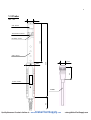
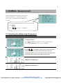
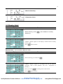
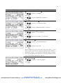
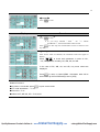
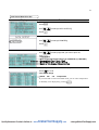
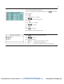
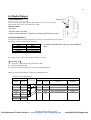
IAQ MONITOR
MODEL 2211
Operation Manual
Please use this instrument properly by reading
this user’s manual and following the warning instructions.
Keep this manual in a place where it can be accessed quickly.
KANOMAX JAPAN INC.
2-1 Shimizu Suita Osaka
Zip:565-0805
Phone: +81(6)6877-0183
Fax : +81(6)6879-2080
02001
04.11
Quality Kanomax Products Online at: www.
GlobalTestSupply.com
[email protected]
Thank you for purchasing Kanomax product.
Please use this
instrument properly by reading this operation manual and
following the warning instructions.
Quality Kanomax Products Online at: www.
GlobalTestSupply.com
[email protected]
List of Components
■ Standard
Items
MODEL
Qty.
Functions
Main Body
2211-00
1
-
Probe
2211-01
1
CO, CO2, temperature, humidity sensor
Carrying case
2211-02
1
Hard case
Probe stand
2211-03
1
Probe fixture
Gas Calibration cap
2211-04
1
Gas calibration
Tubing
-
1
Connecting to gas tank
Operation Manual
-
1
-
Mn Batteries
-
6
-
Software
S221-00
1
Data Processing Software (Windows)
RS232C Cable
6000-02
1
For the connection of Main body and PC
■ Optional
Items
MODEL
ZERO gas
2211-05
Zero point calibration for CO and CO2
CO Span gas
2211-06
CO span calibration (approx. 35ppm)
CO2 Span gas
2211-07
CO2 span calibration (approx. 1000ppm)
Gas valve
2211-08
Valve for gas tank
Spare probe
2211-01
The probe for reserves
Analog output
2211-09
Analog output terminal
AC adapter
6000-05
(AUT-09-0660)
Printer
(Recommended)
DPU-H245
Printer cable
6000-03
Quality Kanomax Products Online at: www.
Functions
Power supply
To print out all calculation result and etc.
For the connection of main body and printer
GlobalTestSupply.com
[email protected]
Table of Contents
1. IAQ Monitor Anatomy.................................................................... 1
1.1 Main Body.................................................................................................................................. 1
1.2 Operation Panel...................................................................................................................... 2
1.3 Probe............................................................................................................................................ 3
2. Getting Started............................................................................... 4
2.1 Installing Batteries ................................................................................................................. 4
2.2 Connecting Probe.................................................................................................................. 5
2.3 Disconnecting Probe............................................................................................................ 5
2.4 Powering IAQ Monitor ON/OFF ..................................................................................... 6
2.5 How to make measurement ............................................................................................. 7
2.5.1 Measuring CO and CO2 and Attentions ......................................................................................7
2.5.2 Measuring Temperature and Attentions.....................................................................................8
2.5.3 Measuring Humidity and Attensions.............................................................................................9
3. NORMAL Measurement............................................................... 10
3.1 Selecting the Measuring Parameters ........................................................................10
3.2 Display Hold............................................................................................................................11
4. Measuring Maximum, Minimum & Mean....................................... 12
5. %OA Mode.................................................................................... 15
6. DATA OUTPUT ............................................................................. 19
6.1 What can be Stored ?........................................................................................................19
6.2 To Recall Stored Data .......................................................................................................19
6.3 Print Out....................................................................................................................................21
6.3.1 Preparation.......................................................................................................................................... 21
6.3.2 NORMAL Mode Print Out ............................................................................................................. 21
6.3.3 CALCULATION Mode Print Out................................................................................................. 22
6.3.4 %OA Mode Print Out.................................................................................................................... 23
6.3.5 Stored Data Print Out .................................................................................................................... 24
6.4 Digital Output .........................................................................................................................27
6.4.1 Preparation.......................................................................................................................................... 27
6.5 To Access From Your PC................................................................................................28
6.5.1 Transmission of On-Time data ................................................................................................... 28
6.5.2 Transmission of Stored Memory ................................................................................................ 29
6.6 Analog Output (Optional) .................................................................................................30
Quality Kanomax Products Online at: www.
GlobalTestSupply.com
[email protected]
7. Other Setting ................................................................................ 33
7.1 Date.............................................................................................................................................33
7.2 Units and Baud Rate .............................................................................................................34
7.3 To Delete Data........................................................................................................................35
7.3.1 To Delete a Page of Data ..................................................................................................... 35
7.3.2 To Delete All Data ................................................................................................................... 36
7.4 Contrast Adjustment...........................................................................................................37
8. Calibrating CO/CO2 Sensor......................................................... 38
8.1 Preparation..............................................................................................................................38
8.2 Calibration Procedure – ZERO Calibration ............................................................39
8.3 Calibration Procedure – SPAN Calibration ............................................................41
9. Specification ................................................................................ 44
10. Calculation Result: DT, WB, AH, and HR................................. 45
10.1 What is DT ............................................................................................................................45
10.2 What is WB...........................................................................................................................46
10.3 What is AH............................................................................................................................46
10.4 What is HR............................................................................................................................47
11. Troubleshooting ........................................................................ 48
11.1 Battery Check........................................................................................................................48
11.2 Initial Operation Check.......................................................................................................48
11.3 Check During Measurement .............................................................................................48
11.4 Printer Check.........................................................................................................................49
11.5 Digital Output Check...........................................................................................................49
11.6 Analog Output Check..........................................................................................................49
11.7 Calibration Check..............................................................................................................50
12.Warranty and After Service...................................................... 51
Quality Kanomax Products Online at: www.
GlobalTestSupply.com
[email protected]
1
1. IAQ Monitor Anatomy
Approx.. 88
1.1 Main Body
Approx. 51
Unit: mm
Probe Terminal
Display
Analog output
Terminal
(Optional)
RS232C
Terminal
Approx. 188
DC
Input
Ternimal
Power Switch
I :ON
O:OFF
Operation
Panel
IAQ MONITOR
Battery Box
Approx. 66
Quality Kanomax Products Online at: www.
GlobalTestSupply.com
[email protected]
2
1.2 Operation Panel
MENU KEY
Press once to access the main menu..
※ If you press this key while measuring or setting, this key will work as CANCEL and bring you back
to the main menu.
…………………………Normal Mode
……………Calculation Mode
…………………………………Ventilation Ratio Mode
……………To download data to your PC or printer
………………To delete data or Printer
…………………… To set date, time and unit
……………Calibration Mode
START/HOLD KEY
This key will start and stop the calculation and/or measurement.
Also works as a hold key.
MENU
START
HOLD
SET
MODE
▲、▼ NAVIGATION KEYS
① In the Normal Mode, this key would allow you to
select the display item of humidity. (See P.41)
CO2
CO
Humidity
CO2
CO2
CO
CO
DT
HR
IAQ MONITOR
CO2
CO
WB
SET KEY
Press the key to execute the selected item.
CO2
CO
AH
② Press this key to scroll in the desired direction.
MODE KEY
You can select the mode accordingly.
CO2
CO
Temperature
Quality Kanomax Products Online at: www.
GlobalTestSupply.com
CO2
CO
Humidity
[email protected]
3
1.3 Probe
Unit: mm
φ25
CO sensor
Temperature sensor
169
Humidity sensor
CO2 sensor
43
φ32
320
φ15
Probe number
53
L=2000
Quality Kanomax Products Online at: www.
GlobalTestSupply.com
[email protected]
4
2. Getting Started
2.1 Installing Batteries
Place IAQ Monitor facedown.
①Press down on the battery cover.
②Slide the cover until it stops.
③Lift the cover away from the body.
④Insert the battery observing the polarity. This instrument requires
6 AA size batteries. Use only AA size Manganese (R6), alkaline
(LR6) or Ni-Cd batteries for replacement.
DO NOT mix new batteries with used ones, for it may lead to leakage.
※Batteries CANNOT be recharged by optional AC adapter.
The batteries that can be used
・Manganese(AA)
・Alkaline(AA)
・Ni-MH(AA)
⑤ Put the cover back on by reversing the
procedure ②, ③.
Quality Kanomax Products Online at: www.
GlobalTestSupply.com
[email protected]
5
2.2 Connecting Probe
※ Make sure that the power is OFF when connecting or
Disconnecting Probe/Probe cable.
① Main Body connector and probe connector only fit one way.
①
②Push-in the connector until you hear click.
※ DO NOT FORCE to connect Probe,
it may cause a serious damage to the instrument.
Probe Terminal
②
2.3 Disconnecting Probe
※ Make sure that the power is OFF when connecting or disconnecting.
①Pull up the lock ring of Probe.(see chart ①-A)
①
①
A
②Pull out Probe from Main Body
with the lock ring up (see chart ②).
※ DO NOT rotate Probe while connected,
it may cause a serious damage to the instrument.
②
Quality Kanomax Products Online at: www.
GlobalTestSupply.com
[email protected]
6
2.4 Powering IAQ Monitor ON/OFF
You can turn ON and OFF the IAQ Monitor by flicking the switch on the side. When you turn on the power after
connecting Probe , Manufacturer’s logo, model name and its software version appear on the display for a few
seconds.
POWER
I
ON
O
OFF
Connect probe to Main body.
Power ON.
You will see the above warning when Probe is not properly
connected or not connected at all. Turn off the instrument,
check Probe connection and try again.
Calibrated Day
Display Icons: (see P.10)
① Current Date and Time ④ Temperature (Humidity)
⑤ Battery Level indicator
② CO2
③ CO
⑤
①
②
③
④
Normal Mode
◆ Battery Level Indicator
The Battery Level Indicator appears in the upper
right corner, and it is difficult to predict the battery life.
This “Battery Indicator” gives you the battery status and
reminds you the timing for battery replacement.
The indicator changes as you see it below:
(blinks)
― LOCK ―
Time to replace batteries
When
is displayed, every function of the instrument will be
locked. The measurement will stop and data will NOT be saved.
Please pay an attention.
Quality Kanomax Products Online at: www.
GlobalTestSupply.com
[email protected]
7
2.5 How to make measurement
2.5.1 Measuring CO and CO2 and Attentions
The diffusion state of the air(State of flow) affects response time of CO and CO2 sensor. In order to
obtain an exact measurement result, please measure in the place which has the flow of air as much
as possible.
Mechanism of CO and CO2 sensor has a limitation in accuracy when measurement takes place
under drastic thermal change. When a sensor and measuring object have apparent thermal
discrepancy, leave a probe in open air for at least 20 minutes before you start a measurement.
After turning a POWER ON, sensor circuit requires 5 minutes to warm-up. For an accurate
measurement result, please wait for 5 minutes after turn the Power ON.
Keep this sensor away from expiratory air; exhaled air contain more than 10,000ppm of CO2 and
exhaled cigarette smoke contains a few ppm of CO. We recommend you to place a probe on the
provided probe stand.
<How to use a Probe Stand>
Lightly push grip part of probe into holder of probe stand.
※ Be sure to place the probe stand on the horizontal and stabilized stand. Unstable place may cause
probe stand to fall and damage the probe.
①
②
Holder
Probe Stand
Quality Kanomax Products Online at: www.
GlobalTestSupply.com
[email protected]
8
<Compensation>
when atmospheric pressure of the place to measure is different from normal atmospheric pressure
(such as high altitude), Please follow below steps for Atmospheric pressure setting (Initial value:
1013hPa).
Since the change of weather does not significantly affect the atmospheric pressure as long as the
place to measure is same (Exclude the case of typhoon), you need to set Atmospheric Pressure only
1 time.
Display
Procedure
Press
.
to select [7.CALIBRATION] .
Use
press
.
Use
press
to select [3. ATMOS. PRESS SET]
.
Use
Press
to set Atmospheric Pressure value.
.
Use
Press
to select Select [4. SAVE INFO.].
.
※This will complete the setting and you are back in Main Menu.
2.5.2 Measuring Temperature and Attentions
Responsiveness of the temperature measurement is proportional to the speed of airflow. We
recommend for you to use the displayed value when reading becomes stabilized.
With no airflow is present, temperature reading value may be slightly higher than actual temperature
due to the heat generated by this sensor. For accurate temperature reading, we recommend for you
to use at least 0.1m/s of airflow.
Quality Kanomax Products Online at: www.
GlobalTestSupply.com
[email protected]
9
2.5.3 Measuring Humidity and Attensions
High humidity or rapid temperature change in atmosphere may cause humidity reading value to be
exceedingly high because of the condensation occurred on this sensor. Incase of the condensation,
leave a probe under atmosphere of less than 40%RH for 24 hours to dry.
Comparison: Assman Aspirated Psychrometer
The quality and accuracy of IAQ Monitor humidity measurement function is ensured by strict
calibration with traceability in Japanese National Standards of JEMIC (Japan Electric Meters
Inspection Corporation). This instrument provides stable measurement as an electronic hygrometer,
can be used as a replacement of conventional Assman Aspirated Psychrometer. Assman Aspirated
Psychrometer often reads higher humidity when comparison is made with IAQ Monitor. Handling and
condition, such as wrapping and dust, drastically affect Assman Aspirated Psychrometer, so that such
handling must be done in caution.
For more information on proper handling of your Assman Psychrometer, please fere to the Japanese
Industrial Standard (JIS-Z8806 “Measuring Method for Humidity”).
Quality Kanomax Products Online at: www.
GlobalTestSupply.com
[email protected]
10
3. NORMAL Measurement
This is the mode that you will be in, when you first
turn on the instrument. In this mode you cannot
save any data. The display will be updated every
1 second.
To move to NORMAL Mode from other measuring mode,
Press
Use
.
to select “1. NORMAL”.
3.1 Selecting the Measuring Parameters
Display
Procedure
①
<NORMAL MODE>
Press
, and display mode moves in order, as shown below.
②CO, CO2, Temperature→① CO, CO2, Humidity
②
<CO2, CO Humidity Measuring>
Press
, and display mode moves in order, as shown
below, Humidity, Dew Point Temperature [DT], Wet-bulb
Temperature [WB], Absolute Humidity [AH], and Humidity Ratio
[HR]).See P.45 for detailed information for each item.
③
<Due Point Temperature>
④
<Wet-bulb Temperature>
Quality Kanomax Products Online at: www.
GlobalTestSupply.com
[email protected]
11
⑤
<Absolute Humidity>
⑥
<Temperature Ratio>
3.2 Display Hold
Display
Procedure
While measuring, Press
(Also available on Humidity
measuring.)
“HOLD” indicator appears on the display to indicate that the reading
shown is held.
Press
again to release.
Maximum Hold・・・How to Hold the Maximum Value
Display
Procedure
While measuring, press and hold
.
“HOLD” indicator appears on the display and you can hold the
maximum value of each parameter (CO, CO2 、 temperature or
humidity ).
When you release
Press
Quality Kanomax Products Online at: www.
, the reading shown will be frozen.
again to release.
GlobalTestSupply.com
[email protected]
12
4. Measuring Maximum, Minimum & Mean
Calculation Mode will automatically calculate the maximum, minimum and mean of measured data.
TRIAL(1)
TRIAL(2)
TRIAL(N)
● Average (AVG)
AVG=ΣTRIAL(N)/N
● Maximum (MAX)
MAX=TRIAL(i)
Sampling Time
Measuring Time・・・ Sampling Time × N(Number of Trial)
Display
● Minimum
MIN=TRIAL(j)
Procedure
Press
.
to select “2. CALCULATION”
Use
Press
.
CALCULATION MODE DISPLAY ICONS
Total Memory
Remaining Memory
1.CALCULATION MODE
AVERAGE: Take the average of each second within
sampling time and count it as a 1 measured data.
INSTANT: Make the measurement at the last
second of the sampling time, and count it as a 1
measured data.
2. SAMPLING TIME (1 – 999 sec.)
To set the length of sampling time of measurement.
3. No. TRIAL (1 – 999)
To set the number of trials (data) needed of desired
sampling time.
4. DATA STRORAGE (YES or NO)
5. SET TO START
Save the setting and return to standby.
Quality Kanomax Products Online at: www.
GlobalTestSupply.com
[email protected]
13
Display
Procedure
<To Set CALCULATION MODE>
and select “1. MODE”
Use
Press
.
and select AVERAGE or INSTANT
Use
Press
.
<To Set SAMPLING TIME>
Use
Press
and select “2. SAMPLING TIME”
.
and select SAMPLING TIME (1 to 999sec).
Use
Press
.
<To Set No. TRIAL (N)>
and select “3. No. TRIAL(N)”
Use
Press
.
and select No. TRIAL (1to 999 times).
Use
Press
.
<DATA STORAGE>
Use
Press
and select “4. DATA STORAGE ?”
.
and select YES or NO.
Use
Press
.
※You CANNOT store more than what’s left in the memory. If you
set the number more than the number of remaining data locations, it
automatically adjusts to the amount of remaining memory locations.
(Ex: if there is R0020/1500 remaining, you can only measure 20 times
even if you set the No. TRIAL more than 20.)
<Save the Settings>
Use
Press
Quality Kanomax Products Online at: www.
and select “5. SET TO START”
.
GlobalTestSupply.com
[email protected]
14
<READY>
to start.
Press
Display
Procedure
<While Measuring>
Press
to stop.
If you have selected “ YES ” for “ 4. DATA
STORAGE ?”, the measured data will be stored.
Press
can also stop the measurement but this would not store
any data.
<Result>
After all the trials are finished, the calculated result will appear in
display.
Press
to check each parameter in order of CO 2 ,
CO, Temperature, Humidity, DP, WB, AH, and HR.
In the case of DP, WB, AH, and HR, only mean values are
displayed.
Press
to return to Main MENU. Calculation data will be
stored when [4.DATA STORAGE] is set to [YES].
Related Functions:
■ If printer is connected: press
to print out the result.
■ To recall stored data → P.19
■ Print Out -- P.21
■ What is DT, WB, AH, HR -- P.45,46,47
Quality Kanomax Products Online at: www.
GlobalTestSupply.com
[email protected]
15
5. %OA Mode
%OA MODE is to provide calculation of ventilation ratio with temperature or CO2.
Calculation is based on below formula:
%OA=(R_A - S_A)/(R_A – O_A)×100
Open Air (O_A)
* %OA: Ventilation Ratio
R_A: Temperature and CO2 in respiratory air
S_A: Temperature and CO2 in supplied air
O_A: Temperature and CO2 in open air
Respiration (R_A)
Measurements take place in order of :
Respiratory Air – Supplied Air- Open Air
Respiratory (R_A)
TRIAL(1) (2) (3)
(N)
Supplied (S_A)
Supplied (S_A)
TRIAL(1) (2) (3)
Open Air (O_A)
(N)
TRIAL(1) (2) (3)
(N)
Time needed to measure at a point・・・Sampling Time × N(Number of Trial)
Respiratory Air: R_A=ΣTRIAL(N)/N
Supplied Air: S_A=ΣTRIAL(N)/N
Open Air: O_A=ΣTRIAL(N)/N
<Result>
** Ventilation Ratio (%OA)
%OA = (R_A - S_A) / (R_A - O_A) x 100
The average value in each point is used for the calculation of ventiltation ratio..
Temperature or CO2 concentration velue of each point (TRIAL(1)~TRIAL(N)) will be stored in the memory.
Quality Kanomax Products Online at: www.
GlobalTestSupply.com
[email protected]
16
Display
Procedure
Press
press
and Select [3.OA%] .
<To Set Sampling Time >
to Select [1.MODE]
Use
.
Press
to Select [TEMP.] or [CO2]
Use
.
Press
%OA MODE (Ventilation Ratio Measurement) Display Icons
1. Calculation MODE
TMP. : To calculate by taking in temperature
value.
Total Memory
CO2:
To
calculate by taking in CO2 concentration.
Remaining
Memory
2. SAMPLING TIME (1-999 sec.)
To Set the length of sampling time of measurement.
3. No. TRIAL(N) (1-999times)
To set the number of trials(data) needed of desired
Sampling time.
4. DATA STORAGE (YES/NO)
5. SET TO START
Save the setting and return to standby.
<SAMPLING TIME>
and select [2.SAMPLING TIME]
Press
Press
.
Use
Press
to set an appropriate number (1-999),
.
<NO.TRIAL>
and select [3.No.TRIAL],
Press
Press
.
to select No. TRIAL (1-999),
Press
Press
Quality Kanomax Products Online at: www.
.
GlobalTestSupply.com
[email protected]
17
Display
Procedure
<DATA STORAGE>
Press
Press
to select [4.DATA STORAGE],
.
and select [YES] or [NO],
Use
Press
.
<SET TO START>
Use
Press
and select [5.SET TO START],
.
※ If you press
back to Main Menu.
①
②
③
④
⑤
before saving the settings it will return you
<Ready>
Press
to start.
Display Icons:
①RDY.: Current Status (READY/SAMPLE)
②N 1: Number of data measured including current
③/ 50: Total number of data to be measured
④TMP.: Calculation Mode (TEMP. = temperature)
([CO2] appears for CO2 Mode)
⑤R_A: Measuring point
(R_A: Respiratory Air, S_A: Supplied Air, O_A: Open
Air)
<While Measuring>
①
②
③
④
⑤
①
②
③
④
⑤
Quality Kanomax Products Online at: www.
Press
to stop.
Press
again to resume.
can also stop the measurement but this would not
※ Press
store any data.
<Ready for the Next Measurement Point>
After completing R_A mode measurement, [NEXT] appears to
indicate the standby status for the S_A mode measurement.
Then, S_A mode and O_A mode follows respectively.
GlobalTestSupply.com
[email protected]
18
Display
Steps
<Result>
After all the trials are finishied, the calculated result will appear
in display.
Press
to display average values in order of : R_A, S_A,
and O_A.
Press
to return to main MENU.
If you have selected [YES] for [DATA STORAGE], the result
will be stored.
Related Functions:
■ If printer is connected, press
to print out the result.
■ To recall stored data – P.19
■ Print Out – P.21
Quality Kanomax Products Online at: www.
GlobalTestSupply.com
[email protected]
19
6. DATA OUTPUT
6.1 What can be Stored ?
Measuring
Display
CALCULATION
Mode
%OA Mode
Stored Parameters
All
CO2, CO, temperature, humidity
(including the items of humidity)
Temp.
CO2
%OA; R_A, S_A, and O_A temperature
%OA; R_A, S_A, and O_A CO2 concentration
6.2 To Recall Stored Data
Display
Procedure
Press
to select [4.DATA OUTPUT],
Use
press
.
Use
Press
to select [1.DISPLAY],
.
<To Set Page>
to select the page that you want to recall
Use
Press
.
……………………………Page number
………Mode(Calculation (A): AVERAGE/(I): INSTANT)
………………Measured Date (Year/Month/Day)
………………Time (Hour/Munite/Second)
……………………………Number of Trial
……………………………Page number
……………Mode (%OA(TMP.):temperature or (CO2): CO2 )
………………Measured Date (Year/Month/Day)
………………Time (Hour/Munite/Second)
……………………………Number of Trial
Quality Kanomax Products Online at: www.
GlobalTestSupply.com
[email protected]
20
Display
Procedure
<Recalled Data>
Recalled data will be displayed.
Use
CALCULATION
If
Data number CO2
CO
TEMP.
you
for scroll.
measured
in calculation
mode, you
can
Temperature or Humidity to be displayed by pressing
select
.
%OA (温度の場合)
< Set Calibration Range>
You can select the range of calculation.
(If you are not going to change the data range, Press
to
calculate the entire data.)
Data number
CO2
CO2
CO2
Press
,
Use
Press
to select the first data,
,
Press
Cursor will move to [END].
to selet the last data ,
Use
Press
cursor will appear on [START].
.
to start a calculation
※ You cannot select more than one range.
< In Calculation Mode >
Press
to select the calculation result in order of CO2 > CO
> temperature > humidity > DT > WB > AH > HR.
Only everage value is displayed on DT, WB, AH, and HR.
< In %OA Mode >
%OA Mode: Press
to shift the average value of each point
in order of %OA > R_A > S_A > O_A.
Quality Kanomax Products Online at: www.
Press
to return to page set.
Press
to return to MAIN MENU .
GlobalTestSupply.com
[email protected]
21
6.3 Print Out
You can connect IAQ Monitor to a printer using an RC232C cable
for data printout.
RS232C Port
6.3.1 Preparation
<Need to have>
- Printer (optional)……….. DPU-H245 (Seiko Instruments) - recommended
- Printer Cable (optional)
<Check the Baud Rate >
You need to coordinate the baud rate and data transmission conditions on both Main Body and the printer.
The factory setting of Main Body is as follows:
Data-bit length
8-bit
Parity
None
Stop Bit
1
Delimiter
CRLF
Baud Rate
Base on setting value
※ To change the BAUD RATE, refer to P.34 “Units and Baut Rate”.
For the setting of printer, refer to printer’s operation manual.
<Connecting Printer>
① Connect printer to Main Body using an RS-232C cable.
② Turn ON the IAQ Monitor first, and then turn ON the printer.
③ Make sure that the IAQ Monitor is displaying NORMAL Mode.
6.3.2 NORMAL Mode Print Out
Display
Procedure
Press
to HOLD the display.
Press
to print out.
If printer is not connected properly, you will find “PERR” in lower
left side of the display.
Quality Kanomax Products Online at: www.
GlobalTestSupply.com
[email protected]
22
Examples of Print Out
<NORMAL Mode>
2004/05/12 15:40:45
CO2
523
PPM
CO
1.7
PPM
Temperature 24.4 ゚ C
Humidity
52.7 %RH
…………CO2
…………CO
…………Temperature
…………Humidity
6.3.3 CALCULATION Mode Print Out
Display
Procedure
Press
result.
Quality Kanomax Products Online at: www.
after the measurement and calculation to print out the
GlobalTestSupply.com
[email protected]
23
6.3.4
%OA Mode Print Out
Display
Procedure
after %OA measurement and calculation to print out the
Press
result.
Examples of Print Out
<CALCULATION Mode>
Measurement Mode
Measured Date
Measured Time
Atmosphericpressure
# of Data
Sampling Time
Calculation Range
CO2
E_A
CO
S_A
Temperature
O_A
%OA
R_A
R_A
R_A
S_A
S_A
S_A
O_A
O_A
O_A
Result
Result
Quality Kanomax Products Online at: www.
Stored Location
PAGE SET
PAGE :002
MODE :%OA(TMP.)
DATE :2004/06/19
TIME :13:35:23
ATM. :1013hPa
DATA :003
SAMPLING TIME:001
START:001 END:003
MAX
25.5 ゚ C
AVG
25.4 ゚ C
MIN
25.4 ゚ C
MAX
24.3 ゚ C
AVG
24.2 ゚ C
MIN
24.1 ゚ C
MAX
23.2 ゚ C
AVG
23.0 ゚ C
MIN
22.8 ゚ C
%OA
85.4 %OA
Condition
Condition
PAGE SET
PAGE :004
MODE :CALCULATION(I)
DATE :2004/06/19
TIME :17:24:33
ATM. :1013hPa
DATA :005
SAMPLING TIME:001
START:001 END:005
MAX
612 PPM CO2
AVG
598 PPM CO2
MIN
567 PPM CO2
MAX
1.2 PPM CO
AVG
0.9 PPM CO
MIN
0.7 PPM CO
MAX
25.6 ゚ C
AVG
25.6 ゚ C
MIN
25.5 ゚ C
MAX
64.6 %RH
AVG
64.5 %RH
MIN
64.4 %RH
DT
15.4 ゚ C
WB
18.1 ゚ C
AH
7.5 g/m3
HR
6.4 g/kg
<%OA Mode>
Humidity
DT
WB
AH
HR
GlobalTestSupply.com
[email protected]
24
6.3.5 Stored Data Print Out
Display
Procedure
Press
.
to select [4.DATA OUTPUT],
Use
Press
.
to select [2.PRINTER],
Use
Press
Use
.
to select page that you want to print out,
press
.
……………………………Page number
………Measurement Mode(Calculation (A): AVERAGE, (I): INSTANT)
………………Measured Date (Year / Month / Day)
………………Measured Time (Hour : Minute : Second)
……………………………Number of Trial/Number of Measuring Point
The data you have selected will be displayed.
Press
to scroll.
………… Calculation Range
……Data# CO2 CO Temperature
If you measured in CALCULATION mode, you can select Temperature
or Humidity to be displayed by pressing
Quality Kanomax Products Online at: www.
GlobalTestSupply.com
.
[email protected]
25
<Set Print Out Range>
You can select the range of calculation.
(If you are not going to change the data range, press
to calculate
the entire data.)
Press
.
Cursor will appear on “START”
to select starting point.
Use
Press
.
Cursor will move to “END”
Use
Press
Press
to select l.
.
to calculate.
You CANNOT set more than one range.
Press
Use
Press
to select the content of the Print Out.
to select.
to print out.
1. RESULT……Condition and Calculation Result
2. DATA………Condition and Stored Data
3. ALL…………Condition, Calculation Result and Stored Data
Quality Kanomax Products Online at: www.
GlobalTestSupply.com
[email protected]
26
Example of Print Out
<CALCULATION Mode>
PAGE SET
PAGE :011
MODE : CALCULATION(I)
DATE :2004/06/21
TIME :16:23:08
ATM. :1013hPa
DATA :005
SAMPLING TIME :001
START:001 END:005
MAX
612 PPM CO2
AVG
598 PPM CO2
MIN
567 PPM CO2
MAX
1.2 PPM CO
AVG
0.9 PPM CO
MIN
0.7 PPM CO
MAX
25.6 ゚ C
AVG
25.6 ゚ C
MIN
25.5 ゚ C
MAX
64.6 %RH
AVG
64.5 %RH
MIN
64.4 %RH
DT
15.4 ゚ C
WB
18.1 ゚ C
AH
7.5 g/m3
HR
6.4 g/kg
NUM. PPMCO2 PPMCO ゚ C
001
612
1.2
002
601
1.0
003
598
1.0
004
577
0.7
005
567
0.7
<%OA Mode>
Condition
(Always printed out)
Calculation Result
(Result)
25.6
25.6
25.5
25.6
25.5
Quality Kanomax Products Online at: www.
Stored Data
(DATA)
PAGE SET
PAGE :002
MODE :%OA(TMP.)
DATE :2004/06/19
TIME :13:35:23
ATM. :1013hPa
DATA :010
SAMPLING TIME:001
START:001 END:010
MAX
25.5 ゚ C
R_A
AVG
25.4 ゚ C
R_A
MIN
25.4 ゚ C
R_A
MAX
24.3 ゚ C
S_A
AVG
24.2 ゚ C
S_A
MIN
24.1 ゚ C
S_A
MAX
23.2 ゚ C
O_A
AVG
23.0 ゚ C
O_A
MIN
22.8 ゚ C
O_A
%OA
85.4 %OA
NUM. ゚ CR_A ゚ CS_A ゚ CO_A
001
25.5
24.3
23.2
002
25.5
24.2
23.1
003
25.5
24.2
23.1
004
25.4
24.2
23.1
005
25.4
24.2
23.0
006
25.4
24.2
23.0
007
25.4
24.2
23.0
008
25.5
24.2
22.9
009
25.4
24.1
22.9
010
25.4
24.1
22.8
GlobalTestSupply.com
[email protected]
27
6.4 Digital Output
RS232C Port
6.4.1 Preparation
You can download the data stored in IAQ Monitor to your PC, by connecting
IAQ Monitor and your PC with the RC232C cable.
<Need to Have>
- Computer
- RS-232C cable (provided)
- Data Processing Software (Software for Windows DC-ROM is provided)
<Check the Baud Rate >
You need to coordinate the data transmission conditions on both Main Body and your PC.
The factory setting of Main Body is as follows:
Data Bit Length
※ To change the BAUD RATE, refer p.34 “Units and Baud
8 bits
Parity
None
Rate”.
Stop Bit
1
Delimiter
CRLF
Baud Rate
Bace on the setting
For setting your PC, refer to the operation manual of your PC
<Connecting PC>
① Connect PC to Main Body using an RS-232C cable.
② Turn ON the IAQ Monitor.
③ Make sure that the IAQ Monitor is displaying NORMAL Mode.
Make sure that the IAQ Monitor is displaying NORMAL Mode.
RS232C Cable Wiring Diagram
PC (D-Sub9 pin)
Signal
Pin No.
NC
RXD
TXD
NC
GND
NC
RTS
CTS
NC
1
2
3
4
5
6
7
8
9
IAQ Monitor (MODEL2211)
Connection
Quality Kanomax Products Online at: www.
Pin No.
Signal
Purpose
Direction
1
2
3
4
5
6
GND
TXD
RXD
CTS
RTS
NC
Ground
Transmitting
Receiving
Transmission Approval
Transmission Request
Output
Input
Input
Output
GlobalTestSupply.com
[email protected]
28
6.5 To Access From Your PC
Command
D****
N
S
To connect IAQ Monitor to your PC, please
refer to p.27.
―――Icons and its Meaning―――
: Space
: Return or Press Enter
*: A Number
※Please input all commands with a capital letter.
U
K
P
T****
M****
B
Function
Number of Downloading Data
Cancel
Output of Measuring Condition (of
On-Time Data)
Output of Measuring Units
Output of Duct Shape/Size
Output of Page Number
Output of Stored Data
Output of Measuring Condition (of
Stored Data)
Output of Measuring Condition of
All Pages
6.5.1 Transmission of On-Time data
Display
Procedure
Example:
Measuring Model and typed Entered <Set Number of Data Needed>
Press “D**** ” (※Must type in 4 digits)
[D0005 ].
After “AD”, the data will be displayed.
AD
Each data represent 1sec of measurement. If you ask for 20 data, it
0.9;
576;
23.4;
63.4
takes approximately 20sec to display.
The maximum number that can be set is 999. If you need more,
0.8;
556;
23.4;
63.3
re-send the command.
0.8;
534;
23.5;
63.2
0.9;
0.9;
540;
561;
23.5;
23.4;
63.2
63.3
<Output Content>
CO; CO2; Temperature; Humidity
<To Cancel>
Press “N ”
AN
Display
AS
CTH;00;00;1013
Quality Kanomax Products Online at: www.
Procedure
<To Download Measuring Conditions>
Press [S ]
After “AS”, the data will be displayed.
Contents
CTH;CO range; temperature range; atmosphere pressure
CO range -- 00: 0-50PPM, 01: 0-500PPM
Temperature range – 00: 0-60℃, 01: -20-60℃
GlobalTestSupply.com
[email protected]
29
Display
Procedure
<To Download Measuring Units >
Press [U ]
After “AU”, the data will be displayed.
AU
ppm;ppm;゚ C;%RH;゚ C;゚ C;g/m3;g/kg;%
Output
CO Unit; CO2 Unit; temperature Unit; humidity Unit ; DT
Unit; WB Unit; AH Unit; HR Unit; OA% Unit
6.5.2 Transmission of Stored Memory
Display
Procedure
<Enable humidity data output>
Press [F ] , after [AF] ,
Humidity related data (such as DT, WB, AH, and HR) will be
displayed.
Procedure
<To release humidity >
Press [G ] , after [AG]
Humidity related data (such as DT, WB, AH, and HR) will be
displayed.
Procedure
<To Download Page Number >
Press [P ] , after [AP]
Number of stored page will be displayed.
Procedure
AF
Display
AG
Display
AP
P0011
Display
AT
2004/05/19;13:32:26
0.9;
576;
001;
0.8;
556;
002;
003;
0.8;
534;
0.9;
540;
004;
005;
0.9;
561;
23.4;
23.4;
23.5;
23.5;
23.4;
63.4
63.3
63.2
63.2
63.3
<To Download Stored Data >
Press “T**** ” (※Must type in 4 digits)
Type in the desired page number after “T”.
After “AT”, the data will be displayed.
※ The numbers will be displayed in currently selected units.
NOT in units of at saving the data.
(As for %OA, only the average value in a page is outputted)
※ Calculated data will not be downloaded.
Output
- CALCULATION Mode ( pre [F] command)
Data#; CO; CO2; temperature; humidity
- CALCULATION Mode ( post [F] command)
Data#; CO; CO2; temperature; humidity; DT; WB; AH; HR
- %OA Mode:
Data#; %OA; R_A; S_A; O_A
Quality Kanomax Products Online at: www.
GlobalTestSupply.com
* Data setting of IAQ Monitor
does not affect the data
setting: date format is fixed
to YY/MM/DD.
[email protected]
30
Display
Procedure
AM
CTH;000;001;003;AVG;1013
①
② ③
④
<To download measurement condition>
Press “M**** ” (※Must type in 4 digits)
Type in the desired page number after “AM”.
⑤
③ Number of Data
④ Calculation setting
CALCULATION -- AVG: average, INS: Instant
%OA -- TMP: temperature CO2; CO2
⑤ Atmosphere pressure
Contents
① Measuring Mode
000: CALCULATION Mode
001: %OA Mode
② Sampling Time
Display
AB
CTH;000;001;003;AVG;1013
CTH;001;001;005;TMP;1013
Procedure
<To download measurement conditions of all pages>
Press [B ] , after[AB]
The data will be displayed.
Display
ED
Procedure
<Error Message>
"ED" will be returned if the number of pages etc. is incorrect-inputted.
6.6 Analog Output (Optional)
① Data Update Interval ………1 second
② Load Impedance…… Above 5KΩ
④ Output Current………………DC 0-1V
Analog Output Port
For the analog output, you must select one setting from the table below.
Output Range
Conversion Formula
(Voltage: V)
0 – 50 ppm
C = 50 x V ppm
CO (C)
0 – 100 ppm
C = 100 x V ppm
0 – 250 ppm
C = 250 x V ppm
0 – 500 ppm
C = 500 x V ppm
0 – 500 ppm
M = 500 x V ppm
CO2 (M)
0 – 1000 ppm
M = 1000 x V ppm
0 – 2500 ppm
M = 2500 x V ppm
0 – 5000 ppm
M = 5000 x V ppm
Temperatur 0 – 50 ℃
T = 50 x V ℃
e(T)
0 –100 ℃
T = 100 x V
℃
-20 – 30 ℃
T = 50 x V – 20 ℃
-20 – 80 ℃
T = 100 x V – 20 ℃
Temperatur 32 – 122 oF
F = 90 x V + 32 oF
o
e(F)
32 – 212 F
F = 180 x V + 32 oF
o
-4 – 86 F
F = 90 x V – 4 oF
-4 – 176 oF
F = 180 x V – 4 oF
Humidity
0 – 50 %RH
H = 50 x V %RH
(H)
0 – 100 %RH
H = 100 x V %RH
Quality Kanomax Products Online at: www.
GlobalTestSupply.com
[email protected]
31
Of the output range, the low end will be set at 0V and the high end will be set at 1V .
Data output interval is always 1 second.
Way To Take In Measured Data
Explanation
(analog output)
V
Take the data at every
1 second, output the
value every 1 second.
0
1
2
3
4sec.(Time)
Display
Procedure
Press
to select [6.UTILITY],
Use
Press
.
Use
Press
to select [3.ANALOG OUTPUT].
.
<To Select Data >
to Select [1.OUTPUT SELECT],
Use
press
to select CO, CO2 (CO2), TMP. (temperature),
Use
and HUM. (humidity).
Select the data
Press
.
<To Set Output Range>
to select [2.]
Use
Press
.
Use
Press
Quality Kanomax Products Online at: www.
to select the range
.
GlobalTestSupply.com
[email protected]
32
<To save the setting>
Use
to select [3.SAVE INFO].
Press
※If you Press
before you save, you will return to Main
Menu and setting will not be saved.
Quality Kanomax Products Online at: www.
GlobalTestSupply.com
[email protected]
33
7. Other Setting
7.1 Date
DISPLAY
PROCEDURE
Press
.
to select “7. UTILITY”.
Use
Press
.
Use
Press
to select “1. TIME ADJUST”.
.
Use
to select "1.STYLE" or "2.DATE".
Press
.
1.STYLE: Select JP,US or EU
Japanese style(JP) YYYY/MM/DD
US style(US)
MM/DD/YYYY
EU style(EU)
DD/MM/YYYY
2.DATE: Date
3.TIME: hour/minute/sec
Use
to select the desired item.
Use
to change the setting.
to move the cursor back to “1” or “2”.
Press
<To Save the Setting>
Use
Press
to select “3. SAVE INFO”.
.
※If you press
before you save, you will return to Main Menu
and the setting will not be saved.
※ Date of the output to the display or printer depends on this setting.. But the style of the
output to digital port (RS-232C) is fixed as Japanese style.
Quality Kanomax Products Online at: www.
GlobalTestSupply.com
[email protected]
34
7.2 Units and Baud Rate
<Units Conversion Table>
Temperature T(oF)=1.8×T(℃)+32
Absolute Humidity 1(g/m3)=6.24×10-5(lb/ft3)
Humidity 1(g/kg)=9.9999×10-4(lb/lb)
DISPLAY
PROCEDURE
.
Press
to select “6. UTILITY”.
Use
Press
.
Use
Press
to select “2. UNIT SELECT”.
.
to select the desired item (1 thru 5).
Use
Press
.
o
……Temperature: ℃ or F
… Absolute Humidity: g/m3, lb/ft3
……Humidity Ratio: g/kg, lb/lb
……Baud Rate: 4800,9600,19200,38400bps
Use
Press
to change the setting.
.
<To Save the Setting>
Use
Press
to select “5. SAVE INFO”.
.
※ If you press
before you save, you will return to Main Menu
and the setting will not be saved.
Quality Kanomax Products Online at: www.
GlobalTestSupply.com
[email protected]
35
7.3 To Delete Data
7.3.1 To Delete a Page of Data
DISPLAY
PROCEDURE
Press
.
to select “6. DATA CLEAR”.
Use
Press
.
Use
Press
to select “1. CLEAR”.
.
……Starting Page Number
……Ending Page Number
……Partial Delete (YES or NO)
……All Delete (YES or NO)
……Remaining Memory / Total Memory
Use
Press
to select the starting page.
.
Use
Press
to select the ending page.
.
Use
Press
Quality Kanomax Products Online at: www.
to select “YES” for partial delete.
.
GlobalTestSupply.com
[email protected]
36
Selected page will be deleted and the remaining data will shift up.
(See diagram below)
Page
Page
Page
Page
1
2
3
4
Page 1
Page 2
Page 4
Page 1
Page 2
Page 3
Page Number will change automatically
7.3.2 To Delete All Data
DISPLAY
PROCEDURE
Press
.
to select “5. DATA CLEAR”.
Use
Press
.
Use
Press
to select “2. ALL CLEAR”.
.
……All Delete (YES or NO)
……Remaining Memory / Total Memory
Use
Press
to select “YES” to delete.
.
All the data will be deleted and the Remaining Memory will be 1500.
Quality Kanomax Products Online at: www.
GlobalTestSupply.com
[email protected]
37
7.4 Contrast Adjustment
In case you find the LCD display of Main Body too dark or too light, there is
an adjusting volume at the back, bottom of Main Body, inside the battery
cover.
You can adjust by using a precision driver (-) (0.9~1.5mm).
Turn it clockwise to darken and vice versa.
Low
High
Contrast Adjuster
Quality Kanomax Products Online at: www.
GlobalTestSupply.com
[email protected]
38
8. Calibrating CO/CO2 Sensor
8.1 Preparation
Please turn on the main unit to fully warm up (about 10 minutes) before calibration.
In general, calibrate in order of ZERO gas prior to Span gas (The calibration of only either ZERO gas or
Span gas is possible).
② Attach the regulator to
ZERO Gas tank.
① Please check the valve of
regulator is closed
Close
Valve
Open
Turn to Turn to
The back the front
③ Connect regulator to calibration cap by the
tube. Connect firmly so that gas does not leak.
Quality Kanomax Products Online at: www.
④ Insert the calibration cap into probe.
Insert firmly so that gas does not leak.
GlobalTestSupply.com
[email protected]
39
8.2 Calibration Procedure – ZERO Calibration
Display
Procedure
Connect ZERO gas tank and IAQ Monitor.
Press
to select [7.CALIBRATION]
Use
Press
.
Use
Press
to select sensor (1.CO2 or 2.CO).
. (CO2 is selected in the example.)
Use
Press
Use
to select [ZERO].
.
to select [1.ZERO], press
.
……Currently calibrating sensor (CO or CO2)
……The value before calibration
Quality Kanomax Products Online at: www.
GlobalTestSupply.com
[email protected]
40
‘‘‘‘
Use
Press
to select [YES].
to start calibration.
Fully open the regulator valve to pour the gas flow,
Press
to start calibration.
Standby screen:
The initial value of countdown is
displayed.
Unit: Second.
………………………………Calibration is performing.
………………………………The remaining time to a calibration end.
When the calibration result is OK
Calibration is completed.
……The value after calibration
…………………Calibration is completed
…………………Calibration result is OK
Result of ZERO Calibration:
CO calibration fails when…
- CO concentration maintains above
10ppm for more than 30 seconds.
- Value does not fall within 6ppm of
Operation
If [END] is displayed, the valve of regulator will be closed
And gas will be stopped.
Press
to save all datas and return to MENU.
pre-calibration value, which is taken
If you press
20 second before calibration.
and the setting will not be saved.
Quality Kanomax Products Online at: www.
before you save, you will return to Main Menu
GlobalTestSupply.com
[email protected]
41
Calibration result is NG
……The value after calibration
…………………Calibration is completed
…………………Calibration Result
Operation
Result of ZERO Calibration:
If [END] is displayed, the valve of regulator will be closed and
Gas will be stopped.
CO2 calibration fails when…
- CO2 concentration maintains above
※ If [2.SAVE INFO] will not be able to be selected, the result is
200ppm for more than 30 seconds.
NG.
- Calibration value does not fall within
Select [YES] to retry the calibration.
100ppm of pre-calibration value,
Press
which is taken 20 second before
※ If [--ERR--] is displayed, please check,
calibration.
to open MENU screen.
return to MENU for retrying the calibration.
8.3 Calibration Procedure – SPAN Calibration
Display
Procedure
Connect Span gas to IAQ Monitor.
Press
to select [7.CALIBRATION].
Use
Press
Use
.
to select the sensor for calibration (1.CO2 or
2.CO).
Press
. (CO2 is selected in the example)
To start SPAN gas calibration:
Use
Quality Kanomax Products Online at: www.
to select [SPAN], press
GlobalTestSupply.com
[email protected]
42
Range of CO mass: 20-550ppm
Range of CO2 mass: 800-5500ppm
Use
Press
Use
tank, Press
to select [1.SPAN].
to display a cursor.
to enter a concentration value displayed on a gas
.
………………Concentration value displayed on gas tank
……The valve before calibration
Use
to select [YES]. Press
・・・・・・・・・・・・・・・・・・・・・・・・・・・・・Standby display
・
・
・・・・・・・・・・・・・・・・・・・・・・・・Shows countdown default value in second.
(CO Calibration:90sec/CO2 Calibration:120sec)
Operation
Replace ZERO gas cylinder with SPAN gas tank:
Fully open the regulator valve to pass the gas flow,
press
to start a calibration.
………………………………Calibration is confirming
………………………………The remaining time to a calibration end.
Quality Kanomax Products Online at: www.
GlobalTestSupply.com
[email protected]
43
Calibration Result is OK
Calibration is completed.
……The value after calibration
…………………Calibration is completed
………………… Calibration result
Result of SPAN Calibration:
CO calibration fails when…
Operation
If [END] is displayed, the valve of regulator will be closed and
Gas will be stopped.
- CO concentration maintains below
60% of standard value for more than
30 seconds.
- Value does not fall within 6ppm
pre-calibration value taken 20 second
Use
Press
to select [2.SAVE INFO].
to save all datas, return to MENU .
before calibration or 6% of standard
value.
If you press
before you save, you will return to Main Menu
and the setting will not be saved.
Calibration Result is NG
Calibration is completed successfully.
The value after calibration
…………………Calibration is completed
…………………Calibration Result
Result of SPAN Calibration:
CO2 calibration fails when…
- CO2 concentration maintains below
Operation
If [END] is displayed, the valve of regulator will be closed and
Gas will be stopped.
60% of standard value for more than
30 seconds.
※ If [2.SAVE INFO] will not be able to be selected, the result is
- Value does not fall within 6ppm
NG.
pre-calibration value taken 20 second
Select [YES] to retry the calibration.
before calibration or 6% of standard
value.
Press
to open MENU screen.
※ If [--ERR--] is displayed, please check,
return to MENU for retrying the calibration.
Quality Kanomax Products Online at: www.
GlobalTestSupply.com
[email protected]
44
9. Specification
Product
Model
Object
Method
Range
Resolution
Accuracy
CO
Compensation: Temp
Compensation:
Air Pressure
Response Time
Method
Range
Resolution
Accuracy
CO2
Compensation: Temp
Compensation:
Air Pressure
Response Time
Method
Range
Temp. Resolution
Accuracy
Response Time
Method
Range
Humidity Resolution
Accuracy
Response Time
Function
Output Function
Power Supply
Battery Life
Condition
Main Body
Probe
Storage
Weight
Standard Kits
Optional Accesories
IAQ Monitor
2211
Clean air flow
Electrochemical
0.0-50.0 ppm(0.0~500 ppm*)
0.0-99.9ppm:0.1ppm,100-500ppm:1ppm
±3% of displayed value or ±3ppm; whichever that is larger (@20℃)
±0.125 %FS/℃ (within ‐20-40℃: standard is 20℃)
±0.02 %FS/hPa (within 700-1200hPa: standard is 1013hPa)
Approx. 60sec. (90%responsive, with calibration cover)
NDIR (Non-Distributed Infrared)
0~5000 ppm
1ppm
±3% of displayed value or ±50ppm; whichever that is larger (@20℃)
±0.34%FS/℃ (within ‐20-40℃: standard is 20℃)
±0.02%FS/hPa (within 700~1200hPa: standard is 1013hPa)
Approx. 45sec. (90%responsive, calibration cover)
Platinum Temperature Measuring Resistive Element
0.0~60.0°C(‐20.0~60.0℃)
0.1 °C
±0.5 °C
Less than 60sec. (velocity:1m/s, 90% responsive)
Electrostatic Capacity
2.0~98.0 %RH
0.1 %RH
2~80%RH:±2.0%RH,80~98%RH:±3.0%RH
Approx. 45sec.(90%responsive)
Measured/Max value HOLD, Battery Indicator (5-level), Time/date,
Barometer comp., Unit selection (Temp/DT/WB: °C or °F, AH:g/m3 or
lb/ft3, OA%:g/kg or lb/lb), Max/Min/Average (interval: 1~999sec., retry:
1~999, Max memory: 1500data), OA%, Gas calibration
Digital output: RS-232C (baud rate:4800,9600,19200,38400bps) for
printer and/or PC
Analog Output: DC0~1V (CO, CO2, temperature, or humidity)
6x AA Batteries, AC Adaptor*: AC100~240V(50/60Hz)
Approx. 10hours
(20℃, alkaline batteries, no RS-232C connection)
5~40 ℃ (no condensation)
‐20~60 ℃ (no condensation)
‐20~60 ℃ (no condensation)
Main body: Approx. 400g (including batteries) Probe: Approx. 250g
Carrying case, Operation manual, AA batteries x6, Calibration cover and
tube, Probe stand, Data processing software for Windows, RS232C
cable
Spare probe, analog output, printer, ZERO gas, SPAN gas for CO/CO2,
flow control valve, AC adaptor
Quality Kanomax Products Online at: www.
GlobalTestSupply.com
[email protected]
45
10. Calculation Result: DT, WB, AH, and HR
10.1 What is DT
DT -- Dew Point Temperature
Air with higher temperature contains more water vapor, and the air reaches a saturation point as
temperature lowered (Relative humidity: 100%). Then continuously lowered temperature causes water
vapor to start condensing -- this temperature is called Dew Point Temperature.
There are many formulas to calculate the Dew Point Temperature; however, this manual uses calculation in
conformity with JIS standard Z8806.
ln(ew)=-6096.9385×T-1+21.2409642-2.711193×(10-2) ×T
+1.673952×(10-5) ×T2+2.433502×ln(T)
e=U/100×ew
y=ln(e/611.213)
When y≧0;
td=13.715×y+8.4262×(10-1) ×y2
+1.9048×(10-2) ×y3
+7.8158×(10-3) ×y4
When y<0;
td=13.7204×y+7.36631×(10-1) ×y2
+3.32136×(10-2) ×y3
+7.78591×(10-3) ×y4
ew: Saturated water vapor pressure (Pa)
T: Absolute temperature (K)=t(℃) + 273.15
T: Dry bulb temperature (℃)
E: Water vapor pressure (Pa)
U: Relative humidity
Td: Dew point temperature (℃)
Quality Kanomax Products Online at: www.
GlobalTestSupply.com
[email protected]
46
10.2 What is WB
Wet Bulb Temperature -- WB
Wet-bulb temperature is measured with a wet-bulb thermometer, which is a regular thermometer with a wet
muslin wick cover.
To calculate wet-bulb temperature without using a wet-bulb thermometer, existing dry-bulb temperature and
relative temperature are used on the aspirated psychrometer humidity table that is JIS standard Z8806
compliant. In this manual; however, we uses Newtonian approximation based on the assumption of a
temperature measured on a wet-bulb thermometer being lower than a dry-bulb thermometer.
ln(etw)=-6096.9385×Tw-1+21.2409642-2.711193×(10-2) × Tw
+1.673952×(10-5) × Tw 2+2.433502×ln(Tw)
A= etw
f’(tw)=4030.183/((235+tw) 2)×A+P/2/755
tw1=tw-(A-P×(t-tw)/2/755-E×U/100)/f’(tw)
tw: Wet bulb temperature (℃)
etw: Saturated water vapor pressure at tw (Pa)
Tw: Absolute temperature (k)=(tw+273.15)
P: Barometric pressure (Pa)
E: Saturated water vapor pressure at t (Pa)
U: Relative humidity
T: Dry bulb temperature (℃)
10.3 What is AH
Absolute Humidity -- AH
Absolute humidity represents an amount of water vapor contents per 1kg of dry air.
To calculate absolute humidity, apply temperature and relative humidity on below formula.
ln(ew)=-6096.9385×T-1+21.2409642-2.711193×(10-2) ×T
+1.673952×(10-5) ×T2+2.433502×ln(T)
e=U/100×eW
D(g/m3)=0.794×(10-2) ×e/(1+0.00366×t)
ew: Saturated water vapor pressure (Pa)
T: Absolute temperature (K)=t(℃)+273.15
t: Dry bulb temperature (℃)
e: Water vapor pressure (Pa)
U: Relative humidity
D: Absolute humidity (g/m3)
Quality Kanomax Products Online at: www.
GlobalTestSupply.com
[email protected]
47
10.4 What is HR
Humidity Mixture Ratio -- -HR
Humidity Ratio (mixture ratio) is the proportion of masses between water vapor and dry air.
Temperature and relative humidity are used on below formula. Society of Heating, Air-conditioning and
Sanitary Engineers of Japan
r=ε×e/(p-e) ×1000
ε: Molar mass ratio = 0.62198
e: Water vapor (Pa)
Reference:
p: Barometric pressure (Pa)
“Understanding Aero-diagram” by Society of Heating,
r: Humidity ratio (g/kg)
Air-conditioning and Sanitary Engineers of Japan
“Humidity and Vaporization” by Masafumi Ueda
Quality Kanomax Products Online at: www.
GlobalTestSupply.com
[email protected]
48
11. Troubleshooting
11.1 Battery Check
Problem
Possible Cause(s) / Solution(s)
IAQ Monitor will not turn ON
The battery is defective.
→Turn OFF the power and replace the batteries.
Contrast is not set properly.
→Adjust the contrast volume switch.
The batteries are low.
→Turn OFF the power and replace the batteries.
Nothing appears on the display
“
” flashes.
Refer To
(Page No.)
4,6
37
4,6
11.2 Initial Operation Check
Problem
Refer To
(Page No.)
Possible Cause(s) / Solution(s)
Display is too dark/light
Screen contrast may need adjustment.
37
→Ajust contrast by turning Contrast Adjuster.
“NO PROBE” is displayed.
Probe is not connected.
5
→Turn OFF the power and connect Probe.
Measurement
appropriate.
unit
is
not Set appropriate unit of temperature (C, oF), absolute
humidity (g/m3, lb/ft3), and humidity ratio (g/kg, lb/lb).
34
11.3 Check During Measurement
Problem
Refer To
(Page No.)
Possible Cause(s) / Solution(s)
“**.*”
is
displayed
measured value.
for IAQ Monitor will show “**.*” for the over-the-range
measurement. It must be used within the range to take the
measurement.
Probe
is not connected property.
“ ‐ ‐ ‐ ‐ ” is displayed for
→Check
the connection.
measured value.
Probe may be damaged.
→Contact your local Kanomax Office or service center.
IAQ Monitor is not displaying Probe sensor may be too close to expiratory air.
the right speed.
Keep a sensor away from expiratory air as much as
possible.
Higher
temperature
is Theoretically, IAQ Monitorcan not mesure temperature in
no-wind environment.
displayed.
→Gently move probe
Assman psychrometer is an intricate instrument and condition
Humidity reading is lower than sensitive. Refer to operation manual of the psychrometer.
Assman psychrometer.
Quality Kanomax Products Online at: www.
GlobalTestSupply.com
44
5
7
8
9
[email protected]
49
11.4 Printer Check
Problem
Unable to printout.
Unable to printout the display.
Printer is not connected properly.
→Check the connection. Re-connect if necessary.
The Baud Rate is not set properly.
→Check both, CLIMOMASTER and printer, settings.
21
21
Printer may not be compatible (DPU-H245 and DPU-201GS
are recommended).
Check your printer type.
Printer connection procedure may not be followed properly.
After a connection is established, you need to turn the IAQ
Monitor power ON, then a printer.
Display is not frozen.
→①Press
②Press
Unable to cancel the print out.
Refer To
(Page No.)
Possible Cause(s) / Solution(s)
to hold the display.
21
21
21
to print out.
You cannot cancel the print out.
21
11.5 Digital Output Check
Problem
Unable to output data
Refer To
(Page No.)
Possible Cause(s) / Solution(s)
Cable may not be connected properly.
Requires RS-232C cable.
27
Baud rate may not be set properly.
Check baud rate setting on IAQ Monitor and printer.
Communication command may not be correct.
27
27
11.6 Analog Output Check
Problem
Unable to output data.
Output appears in tiered pattern.
Refer To
(Page No.)
30
30
Possible Cause(s) / Solution(s)
Polarity of output terminal may be incorrect.
Measured value may be in HOLD status.
Output is set per second.
30
Output data is incorrect.
Analog output setting may be incorrect.
Output value range setting may be incorrect.
Load impedance may be lower than standard value (more than
5kΩ).
Quality Kanomax Products Online at: www.
GlobalTestSupply.com
30
30
30
[email protected]
50
11.7
Calibration Check
Problem
Refer To
(Page No.)
Possible Cause(s) / Solution(s)
[-ERR] appears during the CO Output level of CO sensor may be abnormal or the sensor is
SPAN calibration.
damaged. Contact a distributor near you.
(Although SPAN calibration is not available, you can use
existing calibration value when output level is low.)
[-ERR] appears during the CO2 Output level of CO2 sensor may be abnormal or the sensor is
SPAN calibration.
damaged. Contact a distributor near you.
(Although SPAN calibration is not available, you can use
existing calibration value when output level is low.)
Quality Kanomax Products Online at: www.
GlobalTestSupply.com
41
41
[email protected]
51
12.Warranty and After Service
Kanomax Limited Warranty
The limited warranty set below is given by KANOMAX JAPAN, Inc. (hereafter referred to as “KJI”) with
respect to the KANOMAX brand IAQ Monitor, its attachment parts including Probe and other accessories
(hereafter referred to as “PRODUCT”) that you have purchased.
PRODUCT you have purchased shall be the
only one that the limited warranty stated herein applies to.
Your PRODUCT, when delivered to you in new condition in its original container, is warranted against defects in
materials or workmanship as follows: for a period of one (1) year from the date of original purchase, defective
parts or a defective PRODUCT returned to KJI, as applicable, and proven to be defective upon inspection, will be
exchanged for a new or comparable rebuilt parts, or a refurbished PRODUCT as determined by KJI.
Warranty
for such replacements shall not extend the original warranty period of the defective PRODUCT.
This limited warranty covers all defects encountered in normal use of the PRODUCT, and does not apply to the
following cases:
(1) Use of parts or supplies other than the PRODUCT sold by KJI, which cause damage to the PRODUCT or
cause abnormally frequent service calls or service problems.
(2) If any PRODUCT has its serial number or date altered or removed.
(3) Loss of damage to the PRODUCT due to abuse, mishandling, improper packaging by the owner, alteration,
accident, electrical current fluctuations, failure to follow operating, maintenance or environmental instructions
prescribed in the PRODUCT's instruction manual provided by KJI, or service performed by other than KJI.
NO IMPLIED WARRANTY, INCLUDING ANY IMPLIED WARRANTY OF MERCHANTABILITY OR FITNESS FOR A
PARTICULAR PURPOSE, APPLIES TO THE PRODUCT AFTER THE APPLICABLE PERIOD OF THE EXPRESS
LIMITED WARRANTY STATED ABOVE, AND NO OTHER EXPRESS WARRANTY OR GUARANTY, EXCEPT AS
MENTIONED ABOVE, GIVEN BY ANY PERSON OR ENTITY WITH RESPECT TO THE PRODUCT SHALL BIND KJI.
KJI SHALL NOT BE LIABLE FOR LOSS OF STORAGE CHARGES, LOSS OR CORRUPTION OF DATA, OR ANY
OTHER SPECIAL, INCIDENTAL OR CONSEQUENTIAL DAMAGES CAUSED BY THE USE OR MISUSE OF, OR
INABILITY TO USE, THE PRODUCT, REGARDLESS OF THE LEGAL THEORY ON WHICH THE CLAIM IS BASED, AND
EVEN IF KJI HAS BEEN ADVISED OF THE POSSIBILITY OF SUCH DAMAGES.
IN NO EVENT SHALL RECOVERY
OF ANY KIND AGAINST KJI BE GREATER IN AMOUNT THAN THE PURCHASE PRICE OF THE PRODUCT SOLD BY
KJI AND CAUSING THE ALLEGED DAMAGE.
WITHOUT LIMITING THE FOREGOING, THE OWNER ASSUMES ALL
RISK AND LIABILITY FOR LOSS, DAMAGE OF, OR INJURY TO THE OWNER AND THE OWNER'S PROPERTY AND TO
OTHERS AND THEIR PROPERTY ARISING OUT OF USE OR MISUSE OF, OR INABILITY TO USE, THE PRODUCT
NOT CAUSED DIRECTLY BY THE NEGLIGENCE OF KJI.
THIS LIMITED WARRANTY SHALL NOT EXTEND TO
ANYONE OTHER THAN THE ORIGINAL PURCHASER OF THE PRODUCT, OR THE PERSON FOR WHOM IT WAS
PURCHASED AS A GIFT, AND STATES THE PURCHASER'S EXCLUSIVE REMEDY.
Quality Kanomax Products Online at: www.
GlobalTestSupply.com
[email protected]
52
After Service
Whenever the PRODUCT is malfunctioning, please check with “Troubleshooting” to find possible cause first.
Repair parts are retained for a minimum period of five (5) years after production cessation of the PRODUCT.
This storage period of repair parts is considered as the period during which KJI can provide repair service.
For more information, please contact your local distributor, or call us at KJI’s service desk from 9:00 a.m. to 5:00
p.m. JST on weekdays excluding holidays.
When you make a call, please have the following information of
your PRODUCT at hand:
(1) PRODUCT name;
(2) Model number;
(3) Serial number;
(4) Probe number;
(5) Description of Symptom, and;
(6) Date of purchase
Quality Kanomax Products Online at: www.
GlobalTestSupply.com
[email protected]