1
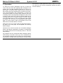
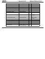
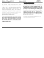
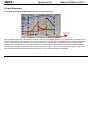
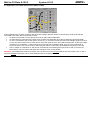
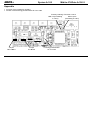
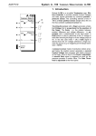
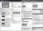
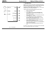
System A-100
DOEPFER
Midi-to-CV/Gate A-190-2
1. Introduction
Module A-190-2 is an economically priced alternative to the
Midi-CV/SYNC interface A-190-1. It can be used in all cases
where the additional features of the A-190-1 are not
required (e.g. clock output, start/stop output). A-190-2 is the
modular version of the MCV4 interface.
These are the most important features of the A-190-2:
•
•
•
•
•
•
•
•
Fig. 1: Schematics
Midi-to-CV/Gate interface
Gate output 0/+5V
CV1: voltage derived from incoming Midi note
messages (0...+5V / 5 octaves), the glide control
affects this CV output
CV2: voltage derived from incoming Midi pitch bend
messages (-2.5 ... +2.5V)
CV3: voltage derived from the multiplication of
incoming Midi volume messages and the velocity
data of the note messages (0...+5V)
CV4: voltage derived from a freely adjustable Midi
control change message (0...+5V)
Midi channel, reference note for 0V CV1 and the
midi control change number for CV4 are adjusted by
means of the learn button.
Glide control: portamento/slew limiter function for
CV1
By means of two jumpers CV1 and Gate can be connected
to the corresponding lines of the A-100 bus.
1
Midi-to-CV/Gate A-190-2
System A-100
2. Overview
Controls / Displays:
1 Learn:
2 Glide:
3 Gate:
!
Learn (momentary switch)
Glide Control for CV output "Note"
Gate / Learn LED
In- / Outputs:
1
2
"
3
§
!
"
§
$
%
&
Midi In:
Gate:
CV Note:
CV Pitch:
CV V/V:
CV Ctrl.:
Width: 6 HP
$
Current: 50 mA
%
&
Fig. 2: Front panel
2
DOEPFER
Midi input
Gate output
CV output "Note"
CV output "Pitch Bend"
CV output "Velocity/Volume"
CV output "Controller"
DOEPFER
System A-100
3. In- / Outputs
! Midi input
The Midi input of the A-190-2 is connected to the Midi output
of the Midi transmitter that is used to control the A-190-2
(e.g. Midi keyboard or sequencer).
" Gate output
The Gate outputs turns "high" when a valid Midi note on
message is recognized by the A-190-2. It turns back to "low"
when the corresponding note off message occurs. The Gate
levels are +5V (high state) and 0V (low state). If desired the
gate polarity can be inverted. Details in chapter 5.
Usually the gate output is connected to the gate input of an
envelope generator (e.g. ADSR A-140) that is used to
control the VCA and/or VCF of the patch.
The A-190-2 has available a jumper that allows to connect
the Gate output of the module to the Gate line of the A-100
bus (see appendix).
Important note: The module comes with an installed Gate
jumper, i.e. one has to remove the jumper if e.g. an A-190-1
or A-185-1 is connected to the gate line of the same bus
board! If the A-190-2 has to be used as Gate source for the
A-100 bus the Gate connection of any other Gate source
(e.g. A-190-1 or A-185-1) has to be removed. Otherwise a
Midi-to-CV/Gate A-190-2
short circuit is made between the outputs of the Gate
transmitters !
§ CV output "Note" (CV1)
This socket outputs a voltage that is controlled by the Midi
note number of a valid note on message (i.e. on the right
Midi channel and in the note range between the reference
note and 5 octaves beyond). The voltage range is 0 … +5V
and the scale is 1V/Octave (i.e. 5 octaves range). 0V
corresponds to the reference note (see chapter 5), +5V to
the note that is 5 octaves beyond the reference note.
CV1 is affected by the glide control (see chapter 4).
A trimming potentiomer can be used to re-adjust the
1V/octave scaling if necessary (see attachment for details).
Usually this CV output is connected to the 1V/Oct
compatible CV input(s) of the voltage controlled oscillator(s)
(VCOs) of the patch. The output is buffered, i.e. it can be
used to control even 2 or more CV inputs of VCOs without
the need of an additional buffer.
The A-190-2 has a jumper on board the allows to connect
the CV output "Note" of the module to CV line of the A-100
bus (see appendix).
3
Midi-to-CV/Gate A-190-2
System A-100
DOEPFER
Important note: The module comes with an installed CV
jumper, i.e. one has to remove the jumper if e.g. an A-190,
A-185-1 or A-185-2 is already connected to the CV line of
the same bus board! If the A-190-2 should be used as CV
source for the A-100 bus the CV connection of any other CV
source (e.g. A-190-1, A-185-1 or A-185-2) has to be
removed. Otherwise a short circuit is made between the
outputs of the CV transmitters !
% CV output " Velocity/Volume" (CV3)
$ CV output "Pitch Bend" (CV2)
Usually this output is connected to the CV input of a voltage
controlled amplifier (VCA) that is used to control the overall
loudness of the patch. But it can be used also to control any
other function by Midi volume or velocity (e.g. filter
frequency, filter resonance, LFO frequency …) .
This socket outputs a voltage that is controlled by valid Midi
pitch bend messages (i.e. on the right Midi channel). The
voltage range is about -2.5V (Midi data 0) … 0V (Midi data
64) … +2.5V (Midi data 127).
Usually this output is connected to the CV input(s) of the
voltage controlled oscillators (VCOs) that are equipped with
attenuators. The attenuators are used to adjust the desired
pitch range. If more than one VCO is used a multiple
module is required to distribute the CV coming from the A190-2. In this case the usage of the precision adder A-185-2
is a more versatile solution (see chapter 6: user examples).
The CV output "Note" of the A-190-2 is patched to one of
the CV inputs of the A-185-2 without attenuator. The CV
output "Pitch Bend" of the A-190-2 is patched to the CV
input of the A-185-2 with attenuator. That way the pitch
bend range is adjusted with one common control only for all
VCOs. The CV bus jumper of the A-190-2 has to be
removed in this application because the A-185-2 is used as
CV source for the bus.
4
This socket outputs a voltage that is controlled by valid Midi
volume or velocity*volume messages. The voltage range is
0 V (velocity/volume data 0) … +5V (velocity/volume data
127). The module can be adjusted for volume control only or
for both volume and velocity (velocity*volume). Details in
chapter 5. The factory setting is volume only (no velocity).
& CV output "Controller" (CV4)
This socket outputs a voltage that is controlled by valid Midi
control change messages (i.e. the right control change
number on the right Midi channel). The voltage range is 0 V
(controller data 0) … +5V (controller data 127). The control
change number can be adjusted to any value. Even this
output can be connected with velocity (same as CV3).
Details in chapter 5. The factory setting is controller #1, i.e.
modulation controller, no velocity.
The output can be used to control any parameter by the
corresponding Midi control change messages (e.g.
modulation depth, filter frequency, wave multiplication
depth, waveform morphing, panorama …).
DOEPFER
System A-100
4. Controls
1 Learn
This is a momentary switch that is used to adjust the
parameters of the A-190-2 in combination with Midi note,
control change or program change messages (e.g. Midi
channel, reference note, control change number, gate
polarity, retrigger on/off, key assign mode). Details in
chapter 5.
The learn button is also used to reset the module (i.e. to call
up the factory settings). For this the button has to be
operated during power on of the A-100 system. Then the
system has to be turned off and on again (with about 10
seconds in the "off" state"). These are the factory settings:
•
•
•
•
•
•
•
•
Midi channel 1
reference note 36
trigger polarity: positive
retrigger: off
CV3: volume (controller #7)
CV4: modulation (controller #1)
CV1 characteristics: V/octave
key assign mode: highest note
Midi-to-CV/Gate A-190-2
2 Glide
This is the glide control for the CV output "Note" (this
function is even called Portamento or Slew Limiting). In the
fully CCW position no glide appears, i.e. the control voltage
jumps when a new Midi note number is recognized. To
obtain the glide function the control has to be turned
clockwise until the desired glide time is reached.
3 Gate/Learn
The LED (light emitting diode) displays the Gate function in
the normal play mode. The LED can be used to control the
correct function of the module – even without having other
modules connected to A-190-2.
The LED is also used as Learn display after the Learn
button has been operated. Details in chapter 5.
5
Midi-to-CV/Gate A-190-2
System A-100
5. Operation
To adjust the A-190-2 parameters one has to enter the
Learn mode and send the regarding Midi messages to the
module from the Midi transmitter while the A-190-2 is in
learn mode. To enter the learn mode one has to press the
learn button and hold it pressed down for about one second.
The one-second-delay was programmed to prevent the
unintentional release of the learn mode. Whenever the LED
is flashing without incoming Midi messages the learn mode
is active. In this mode the A-190-2 is looking forward to an
incoming Midi note on, program change or control change
event (see table below). If one has entered the learn mode
by mistake one can leave it by pressing the learn button
again. The learn mode is also be terminated if one of the
Midi events in the table below is received.
While the A-190-2 is in learn mode the parameters listed in
the table on the next page can be adjusted via incoming
Midi messages.
Whenever the A-190-2 receives one of the Midi messages
listed in the table the parameter in question is changed and
the A-190-2 returnes to the normal play mode, i.e. the LED
stops flashing.
Pay attention that not unintentional Midi messages appear
while beeing in the learn mode (e.g. from a sequencer) as
you change the settings of the A-190-2 with such messages.
All parameter changes made while beeing in the learn mode
6
DOEPFER
are stored non volatile parameter memory. When the A-1902 is turned on next time the parameter settings are taken
from this memory.
DOEPFER
System A-100
Midi-to-CV/Gate A-190-2
Function
Midi channel/reference for CV1=0V
CV3 velocity off
CV3 velocity on
CV4 velocity off
CV4 velocity on
Retrigger: off
Retrigger: on
Trigger polarity: normal
Trigger polarity: invertet
CV3 velocity mode 127 steps
Midi message
Note on
Program Change #1
Program Change #2
Program Change #3
Program Change #4
Program Change #5
Program Change #6
Program Change #7
Program Change #8
Program Change #11
Note
(1)
(2)
(2)
(2)
(2)
(3)
(3)
(4)
(4)
(5)
CV3 velocity mode 2 steps
Program Change #12
(5)
CV4 velocity mode 127 steps
Program Change #13
(5)
CV4 velocity mode 2 steps
Program Change #14
(5)
Key assign mode: highest note
Key assign mode: last note
Key assign mode: reference note
Key assign mode: stack note
Characteristics: V/Octave
Characteristics: Hz/V
Controller for CV4
Program Change #15
Program Change #16
Program Change #17
Program Change #18
Program Change #19
Program Change #20
any Midi-Controller (except
Bank-Controller 0/32)
(6)
(6)
(6)
(6)
(7)
(7)
(8)
Comment
CV3=volume
CV3=volume*velocity
CV4=Ctr.#X
CV4=Ctr.#X*velocity
velocity resolution 0127
velocity 2 steps
(</>100)
velocity resolution 0127
velocity 2 steps
(</>100)
7
Midi-to-CV/Gate A-190-2
System A-100
Notes
(1) Midi channel/reference for CV1=0V
In case of an incoming note event in the learn mode the
note number and the channel of the event are taken over
as the new reference note and Midi channel. The
reference note is the Midi note number that belongs to 0V
CV1 output. In practice you simply enter the learn mode
and press the key on your Midi keyboard that should
belong to 0V CV1. Midi note events below the reference
note or more than 5 octaves above the reference note are
ignored (remember: the CV1 voltage range is 0...+5V).
The factory default settings of reference note and Midi
channel are 36 (C) and 1.
(2)...(6)
For the setting of these parameters Midi Program Change
messages coming from your Midi device are used.
Normally you will have to press the program change keys
on your Midi keyboard or synthesizer or software while
beeing in the learn mode.
Important note: Pay attention that some manufacturers
count the Midi program change numbers from 1....128,
others from 0...127. In this manual the counting 1…128 is
used. Please look into the user's manual of your Midi
8
DOEPFER
device which type of counting is used. If the counting type
0…127 is used one has to subtract 1 from the program
change numbers in the table above. For some devices
(especially software sequencers) the type of program
change numbering can be selected. In this case you
should use the 1...128 range to agree with the numbers in
the table above.
The program change messages must be sent on the A190-2 Midi channel (see note 1).
(2) Velocity on/off
These program change messages are used to select
whether the note on velocity affects the control voltages
CV3 and CV4. If velocity is "off" only volume (CV3) or the
free adjustable controller (CV4) is used to generate the
control voltage. If velocity is "on" the volume or controller
value is multiplied with the note on velocity, i.e. the CV
value changes with every new note event as the velocity
of the note event is used to calculate the control voltage
together with the volume message (CV3) or the
assignable controller (CV4).
DOEPFER
System A-100
(3) Retrigger on/off
With this parameter one can select whether the gate is
reset for a few milliseconds when playing legato (i.e.
playing a new note on the keyboard while the key of the
former note is still pressed). The factory default setting is
retrigger off. Additionally the Midi controllers LEGATO
(controller #68) and SUSTAIN (controller #64) affect the
gate output in the usual manner.
(4) Gate polarity
With this function the gate polarity can be changed.
Within the A-100 this features is not required because all
envelope generators of the A-100 use positive gate
polarity only. Only if the A-190-2 is used to control other
equipment or for special features this function might be
useful.
(5) Velocity resolution
This parameter defines whether the velocity resolution is
127 steps (as usual) or two steps only. The two-stepmode is similiar to the accent used in some vintage
equipment (e.g. TB303, TR808) and could make sense to
simulate one of these devices.
The velocity threshold value for the two-step-mode is 100:
incoming velocity values of 100 or more are converted
Midi-to-CV/Gate A-190-2
into a fixed velocity value 127, incoming velocity values
less than 100 are converted into a fixed velocity value 64.
(6) CV1 Key assign modes
These program change messages adjust the type of
assign modes for CV1. If highest note is selected the
highest key pressed on the midi keyboard is used to
generate CV1 if more than one key is operated. In the last
note mode always the last note (chronological) is taken
for CV1.
The following modes are only useful if two or more A-1902 are daisy-chained via Midi Out/In by means of the
internal jumpers (see attachment).
Reference note means that only the reference note is
accepted. This feature is useful if you want to trigger
different devices on the same Midi channel using two or
more A-190-2. In this case you have to set the reference
notes for the A-190-2's to different values.
Stack note means that the A-190-2 is filtering out the note
event that is used by the A-190-2 to generate Gate and
CV1. The note event in question is not transmitted to the
Midi output. All other note events are passed on. Stack
mode is used to control more than one synthesizer voice
on one Midi channel and enables polyphonic control.
9
Midi-to-CV/Gate A-190-2
System A-100
DOEPFER
(7) CV Characteristics
Temporary parameter changes
With programm change #19 and #20 one can select
between V/Octave and Hz/V characteristics for the CV1
output. Within the A-100 this features is not required
because all VCOs and VCFs use V/Oct only. Only if the
A-190-2 is used to control other equipment this function
might be useful. V/Octave is used by most of the
synthesizer manufacturers (Moog, ARP, Oberheim,
Roland, Sequential Circuits, Doepfer). Because of the non
linear voltage range mode the resolution is very poor in
the Hz/V mode, especially in the lower voltage range.
Consequently the Hz/V mode should be treated as a free
bonus and used only if there is no other solution.
The program change messages listed in the table can be
used to change the settings even temporarily without the
need to select the learn mode. Temporarily means that
the changes are not stored permanently in the nonvolatile parameter memory but only as long as the module
is powered. If the A-190-2 is turned off and on the
previously stored parameter settings are called up again.
(8) Control change number for CV4
If the A-190-2 receives a Midi control change message
(except bank controllers 0 and 32) while being in the
learn mode the control change number of this message
defines the new control change number for CV4 (except
bank controllers 0 and 32). I.e. the CV4 output of the A190-2 corresponds from now on to this controller number.
The control change message must be sent on the A-1902 Midi channel (see note 1).
10
The temporary changes may be used to try out different
settings without storing them into the memory or to
change the settings temporarily from a Midi foot-switch or
sequencer (e.g. retrigger on/off for, assign mode change).
If the parameter changes have to be stored permanently
the learn mode has to be used.
All program change messages must be sent on the A190-2 Midi channel (see remark 1).
DOEPFER
System A-100
Midi-to-CV/Gate A-190-2
6. User Examples
6.1. Simple synthesizer standard patch with one envelope generator
This is a simple synthesizer patch with one VCO A-110 that is processed by a VCF (A-124 Wasp filter in this example, but
any other filter may be used) and two VCAs (Dual VCA A-132-3). The first VCA is controlled by the envelope of the ADSR
A-140. The second VCA is controlled by the Velocity/Volume CV of the A-190-2 and used for a Midi controlled overall
loudness. The VCF frequency is controlled by both the A-140 envelope (width adjustable level) and the Midi generated
Controller CV (fixed level). The dashed blue connections (CV1 A-190-2 → CV1 In A-110 and Gate A-190-2 → Gate In A140) are not required if the bus jumpers of the modules A-110, A-140 and A-190-2 are installed.
11
Midi-to-CV/Gate A-190-2
System A-100
DOEPFER
6.2. Application of A-190-2 and Precision Adder A-185-2
In this application the A-185-2 is used to add up several voltages that are used to control the pitch of all VCOs that are
connected to the same bus board as the A-185-2:
•
CV Note is connected to one of the inputs of the A-185-2 without attenuator
•
CV Pitch Bend is connected to the input of the A-185-2 with attenuator to be able to adjust the pitch bend width
•
CV Ctr is connected to the control input of a VCA (e.g. A-130) and controls the level of the triangle signal of the LFO
A-145. The output of the VCA is connected to one of the inputs of the A-185-2 without attenuator. That way the Midi
controller (e.g. modulation = control change #1) is used for the modulation depth. If the A-145 is replaced by a
VCLFO A-147 the CV Volume of the A-190-2 may be used to control even the modulation frequency of the LFO.
•
The CV output of a sequencer A-155 can be connected to the remaining free input of the A-185-2. Then the CV
Note of the A-190-2 is used to transpose the sequence of the A-155 via Midi.
Attention: In this application the bus CV jumper of the A-190-2 has to be removed and the bus CV jumper of the A-185-2
has to be installed ! Otherwise a short circuit between both CV outputs is made !
12
System A-100
DOEPFER
Midi-to-CV/Gate A-190-2
Appendix
• Function of the jumpers/pin headers
• Position of the trimming potentiometers for CV1 scale
for daisy-chaining of several A-190-2
Midi out (to following
A-190-2)
Jumper
Gate → Bus
Jumper
CV → Bus
Midi in (from
preceeding A-190-2)
Trimming potentiometer
for CV scale
13