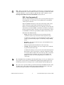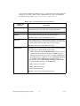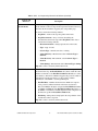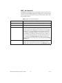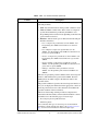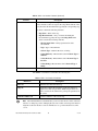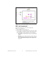
1
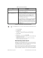
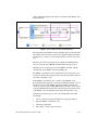
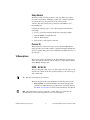
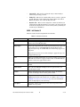
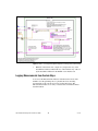
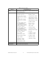
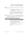
USER GUIDE
Vision Builder for Automated
Inspection Development Toolkit
Version 2.6
Vision Builder AI Development Toolkit User Guide
The Vision Builder for Automated Inspection (Vision Builder AI)
Development Toolkit features a wizard and an application interface (API)
you can use to create custom steps for use in any Vision Builder AI script.
You can create custom steps to provide functionality that is not already
included in Vision Builder AI. For example, you can develop a custom step
that drives a camera or other hardware not currently supported in Vision
Builder AI. You also can create a custom step to include a customized
image processing algorithm.
Note This toolkit is designed for advanced LabVIEW users who have experience
developing LabVIEW applications with IMAQ Vision.
You can distribute custom steps in addition to the released version of Vision
Builder AI, providing your end users with a customized Vision Builder AI
package.
System Requirements
The following list includes minimum system requirements for the Vision
Builder AI Development Toolkit:
•
Processor equivalent to a Pentium III or later/600 MHz Celeron
•
Microsoft Windows 2000/NT/XP. If you are using Windows NT 4.0,
you must have Service Pack 6 or later installed to run
Vision Builder AI.
•
Microsoft Internet Explorer 5.0 or later
•
1024 × 768 resolution video adapter with a 16-bit display
(65,536 colors)
•
256 MB of RAM
•
10 MB of available hard disk space
•
LabVIEW 7.1 or later.
•
IMAQ Vision 7.1.1 (optional, but recommended)
•
Vision Builder for Automated Inspection 2.6.x. You can download the
Vision Builder AI 2.6 updates from ni.com/support.
Installation Instructions
Complete the following steps to install the Vision Builder AI Development
Toolkit:
1.
When installing Vision Builder AI, select the Custom installation
option instead of complete.
2.
In the tree under Vision Builder for Automated Inspection, select
Development Toolkit and select Install this feature to the local
drive.
3.
Click Next.
4.
Follow the setup instructions on your screen.
Note To install the Vision Builder AI Development Toolkit on a Windows 2000/NT/XP
system, you must be logged in with administrator privileges.
The Vision Builder AI Development Toolkit installation process installs
files in the <LabVIEW 7.1>\Project\Vision Builder AI 2.6
directory.
Installing the Toolkit When Vision Builder AI is Already Installed
Complete the following steps to install the Vision Builder AI Development
Toolkit on a system that already has Vision Builder AI installed:
1.
Navigate to the Windows Add or Remove Programs wizard, which
is located on the control panel.
2.
Select National Instruments Software and click Change.
3.
Select NI Vision Builder AI 2.6 and click Modify.
4.
In the tree under Vision Builder for Automated Inspection, select
Development Toolkit and select Install this feature to the local
drive.
5.
Click Next.
6.
Follow the setup instructions on your screen.
Vision Builder AI Development Toolkit User Guide
2
ni.com
Related Documentation
The following documents contain information that you might find helpful
as you work with the Vision Builder AI Development Toolkit:
•
IMAQ Vision Concepts Manual
•
IMAQ Vision for LabVIEW User Manual
•
NI Vision Builder for Automated Inspection: Configuration Help
•
NI Vision Builder for Automated Inspection: Inspection Help
To view the help files listed above, click Help»Online Help from the Vision Builder
AI Configuration and Inspection interfaces, respectively.
Tip
Tip If you do not have IMAQ Vision installed, visit ni.com/manuals and complete the
following steps to search for and display and/or download the IMAQ Vision for LabVIEW
User Manual:
1. Select Vision in Product Line.
2. Enter IMAQ Vision for LabVIEW in Additional Keywords.
3. Click Go.
Creating a Custom Step
Complete the following steps to create a custom step:
1.
Launch LabVIEW 7.1.
2.
Close any open VIs.
3.
Select Tools»Vision Builder AI 2.6»Create Custom Step.
4.
Type a Step Name for the custom step.
5.
Enter a Description for the custom step. The description is displayed
next to the step name in the Vision Builder AI Inspection Steps palette.
6.
Select one of the following template sources:
•
Custom step template
•
Existing custom step you previously created
7.
Click Next.
8.
If you selected Custom step template for the template source, select
one of the following step types based on the demonstrated feature you
want to use:
•
© National Instruments Corporation
Simulated Acquisition Step—Acquires or creates an image and
makes it available to other steps for processing. This step type
demonstrates image acquisition.
3
Vision Builder AI Development Toolkit User Guide
Note You must always start from this step template when you create a custom step that
acquires images.
•
Simple Processing Step—Processes the image from the previous
step but does not return measurements other than the pass/fail
information. This step type demonstrates image processing.
•
Processing Step that Logs Measurements—Processes an image
from the previous step, makes measurements in the image, and
makes the measurements available to subsequent steps. This step
type demonstrates image processing and measurements logging.
•
Generate a Report—Provides access to the measurements
logged from previous steps. You can use the logged measurements
to create new measurements and create a customized pass/fail
condition. This step type demonstrates accessing measurements
logged by previous steps.
•
Global Step Status—This step passes inspection if all of the
previous steps passed. Otherwise, the step fails inspection. This
step does not require IMAQ Vision. If you are developing a
custom step, and you do not have IMAQ Vision installed, select
this template. This step demonstrates how to use the Vision
Builder AI Development Toolkit without IMAQ Vision.
•
Coordinate System—This step demonstrates using coordinate
systems and creating image masks.
In addition to using the custom step templates to create your custom step, you can use
the custom step templates to help determine how you design your custom step. For
example, if you are creating a custom step that combines image processing and creating
image masks, you might create the custom step using the Simple Processing template and
refer to the Coordinate System template for ideas about how to fill out the remainder of the
code to design your custom step to include creating image masks.
Tip
9.
If you selected Existing custom step you previously created for the
template source, select the previously created step you want to copy.
10. Click Next and verify the setup information.
Tip Close all open VIs before you finish creating the custom step to ensure that the custom
step is created successfully.
11. Click Finish to create the custom step.
The Create Custom Step wizard opens the XXXX - All VIs VI, which
provides a project window that contains the VIs you can modify for
your custom step. Refer to the XXXX - All VIs VI section for
information about the XXXX - All VIs VI.
Vision Builder AI Development Toolkit User Guide
4
ni.com
Note Your custom step is not available in Vision Builder AI until you save it for
distribution. National Instruments recommends that you debug your custom step before
you save it for distribution. Refer to the Debugging Custom Steps section for information
about debugging your custom step. Refer to the Distributing Custom Steps section for
information about saving your custom step for distribution.
Custom Step Files
The Create Custom Step wizard creates the following files in the <Vision
Builder AI 2.6>\UserPlugins folder, where <Vision Builder
AI 2.6> is the location where you installed Vision Builder AI 2.6:
•
59XXXX.llb—Source code for your custom step
•
XXXX.tif—Icon for your custom step
In each of these file names, XXXX represents the name of your custom step.
Modifying the Custom Step Icon
Complete the following steps to modify the custom step icon:
1.
Launch a graphics application, such as Microsoft Paint.
2.
Navigate to <Vision Builder AI 2.6>\
UserPlugins\XXXX.tif, where XXXX is the name of the custom
step.
3.
Click Open.
4.
Modify the file as necessary and save it.
Note You must save the file with the .tif file extension.
Note The icon image must be 32 × 32 pixels.
Customizing the Generated VIs
When you create a custom step, the Create Custom Step wizard creates
several VIs that provide the functionality of the custom step. Table 1 lists
the custom step VIs you can modify. Use the block diagram of the
XXXX - All VIs VI to access these VIs.
Note Do not modify any custom step VIs not listed in Table 1.
The Create Custom Step wizard creates the files listed in Table 1, and
installs them to the <Vision Builder AI 2.6>\
UserPlugins\59XXXX.llb file.
© National Instruments Corporation
5
Vision Builder AI Development Toolkit User Guide
Note In each of the VI names listed in Table 1, XXXX represents the name of the custom
step.
Table 1. Custom Step VIs
VI
XXXX - All VIs.vi
Description
Project VI that contains all the VIs you can customize as well
as utility VIs you can use in your step. This VI is a starting
point to easily access all of the VIs for the custom step.
Note: Add any VIs you create and call dynamically to the
block diagram of the XXXX - All VIs VI.
Tip: This VI helps you organize your VIs and is not designed
to be executed.
XXXX - Init Globals.vi
Contains the parameters of the custom step, such as the step
name and description, supported image types, available
tools, tab location, and help files. The step name for the
custom step is the name displayed in the Vision Builder AI
tools palette.
XXXX - User Programming.vi
Contains the code called by the Vision Builder AI engine.
One of the following three modes is specified for this VI:
• Setup
• Execution
• Cleanup
Refer to the XXXX - User Programming VI section for
information about using the VI in each of these modes.
XXXX - User Interface.vi
Vision Builder AI Development Toolkit User Guide
Called by the Vision Builder AI engine when the user clicks
the custom step icon in the Inspection Steps palette or edits
the step already inserted in the script. This VI contains the
user interface of the custom step, which is where the user
specifies the name and parameters of the step.
6
ni.com
Table 1. Custom Step VIs (Continued)
VI
Description
XXXX - Decision Maker
(float).vi
Computes the pass/fail decision of the custom step based on
the measurements computed in the execution mode of the
XXXX - User Programming VI.
XXXX - Parameters.ctl
Contains the type definitions of the user-defined parameters.
Note: The parameters the user selects in the user interface are
stored in a variant that is passed to the XXXX - User
Programming VI. You must use the Variant To Data VI to
extract the data from the variant.
National Instruments recommends you store the user-defined
parameters of the custom step in the XXXX - Parameters
type definition so that you can easily update parameters in
the custom step code. When you make changes in the type
definition, every instance of the parameter is updated in the
LabVIEW code.
Complete the following steps to open the custom step VIs:
Note To avoid linking issues, close any open custom steps before opening another custom
step.
1.
Launch LabVIEW.
2.
Click Open VI.
3.
Navigate to <Vision Builder AI 2.6>\UserPlugins\
59 XXXX.llb, where XXXX is the name of the custom step.
4.
Open the LLB.
5.
Select XXXX - All VIs.vi and click OK.
6.
Open the diagram. The diagram contains each of the customizable VIs
included in the custom step.
7.
Modify the custom step VIs as necessary. Refer to the following
sections for information about each VI.
Data Flow Among Custom Step VIs
The XXXX - User Programming VI is the core of your custom step. The
Vision Builder AI engine sets the value of the Setup variant to the value that
you previously set in the custom step User Interface VI.
Figure 1 shows how the custom step configuration data flows from the user
interface to the execution of the custom step, which occurs in a loop. The
outputs of the XXXX - User Interface VI are saved in the Vision Builder AI
© National Instruments Corporation
7
Vision Builder AI Development Toolkit User Guide
engine, which then dispatches the outputs to the inputs of the XXXX - User
Programming VI.
Figure 1. Decision Making Custom Step Block Diagram
The setup mode of the XXXX - User Programming VI is executed when the
user validates the user interface of the custom step that is being inserted into
the inspection, or when you open an inspection that contains your custom
step.
The image, the value of the Setup variant, and Previous Measurements
array are set by the Vision Builder AI engine when the step executes.
When the user closes the script, the Vision Builder AI engine calls the
cleanup mode of the XXXX - User Programming VI.
The XXXX - User Interface VI is called when the user selects the step to
be inserted or edited. The front panel of this VI is the user interface the user
sees when configuring a step.
In the XXXX - User Interface VI, you must call the XXXX - User
Programming VI in setup mode to perform any initialization before you call
the execution mode of the XXXX - User Programming VI. If the user
validates a custom step by clicking OK in the user interface of the custom
step, Vision Builder AI automatically calls the setup and execution modes
of the XXXX - User Programming VI, inserting the step in the script.
Complete the following steps to view a block diagram that shows this
relationship:
1.
Create a custom step using the Simple Processing Step template.
2.
Open the XXXX - User Interface VI.
3.
View the block diagram.
4.
Select frame 3 of the sequence structure.
Vision Builder AI Development Toolkit User Guide
8
ni.com
Setup Variant
The Setup variant stores the parameters of the step. If the step requests
more than one parameter, bundle the parameters in a cluster, and use the
To Variant VI to store the parameters in the variant. Use the
Variant to Data VI to retrieve these parameters in the XXXX - User
Programming VI.
Complete the following steps to view a block diagram that shows this
relationship:
1.
Create a custom step using the Simple Processing Step template.
2.
Open the XXXX - User Interface VI.
3.
View the block diagram.
4.
Select frame 1 of the sequence structure.
Process ID
When an instance of the custom step is created, the Vision Builder AI
engine provides a Process ID, which is a string that uniquely identifies the
custom step. This string can be used to differentiate multiple instances of
the same step.
VI Descriptions
This section contains descriptions of the VIs included in a custom step as
well as descriptions of the VI controls, indicators, and parameters that the
Vision Builder AI engine uses.
XXXX - All VIs VI
This VI is designed to help you locate and organize all of the VIs you can
customize. It contains all the VIs you must modify for your custom step as
well as utility VIs.
Tip
This VI is not designed to be executed.
The block diagram of this VI is divided into the following four sections:
•
Set Up Global—Contains the XXXX - Init Globals VI. Open this
global first to modify the basic properties of the custom step. Refer to
the XXXX - Init Globals VI section for more information about this VI.
Note The Setup Global section is connected to a string indicator to ensure that the
All VIs VI has no errors. This string indicator serves no other purpose.
© National Instruments Corporation
9
Vision Builder AI Development Toolkit User Guide
•
Custom VIs—This section contains the VIs you must modify to
achieve the processing you want.
•
Utility VIs—This section contains utility VIs you can use to perform
specific functions, such as displaying an image in the main Vision
Builder AI window. You cannot modify these VIs.
•
Dynamic VIs—This section is designed to contain any VIs that you
call dynamically. This design helps you organize your custom step and
ensure that the dynamic VIs are saved correctly when you build your
custom step for distribution.
XXXX - Init Globals VI
This VI contains the following initialization elements.
Table 2. Init Globals VI Elements
Element
Description
Local Name
Name of the step as it appears in the Vision Builder AI Inspection Steps
palette. You can modify this name.
Image Types
Image types supported by the custom step. Disable the image types you
do not want to use. A green LED indicates that the image type is
supported by the step. A red LED indicates that the image type is not
supported.
Note: The user receives an error if he attempts to apply the step to an
unsupported image type.
Tools
ROI tools available. Disable the tools you do not want to use. A green
LED indicates that the tool appears in the toolbar. A red LED indicates
that the tool does not appear in the toolbar.
Default Tool
Default ROI tool. Choose the tool you want the custom step to select by
default.
Tab Location
Tab of the Vision Builder AI Inspection Tools palette where your
custom step is located.
Version
String to help keep track of the custom step version. To check the
version, the developer must read the global variable.
Online Help
File path to your custom help file, which is in the form of compiled
HTML help. The file name extension is .CHM. Refer to the Creating
HTML Documentation for the Custom Step section for information
about creating help for your custom step.
Description
Descriptive text that appears next to the custom step in the Vision
Builder AI tools palette.
Vision Builder AI Development Toolkit User Guide
10
ni.com
Note When you modify the controls and indicators in these VIs, you must make the new
values the default for the control or indicator and save your changes. To make the current
values the default for a control or indicator, right-click the control or indicator, select
Data Operations»Make Current Values Default, and save the VI.
XXXX - User Programming VI
This VI contains the main processing code of your step. The front panel is
never displayed, so it does not have to be modified. Do not modify the
connector pane of this VI.
The Vision Builder AI engine sets the value of the Setup variant control,
which contains the setup parameters defined by the user in the user
interface. Use the Variant To Data VI to access this data. Use the same data
structure that you used in XXXX - User Interface VI when you packaged
the data in the Setup variant. To ensure you use the same datatype, always
use the XXXX - Parameters type definition with the Variant to Data VI.
The VI has three different modes:
•
Setup—Executed once when the user opens an inspection that
contains the custom step or inserts the custom step in the script.
Use this mode to perform any one-time initialization routines, such as
reading a pattern matching template or initializing a DAQ or IMAQ
device.
•
Execution—Executed each time the step is called within the Vision
Builder AI inspection.
This mode performs the main function of the custom step.
•
Cleanup—Executed when the user closes an inspection or when the
step is removed from the script.
Use this mode to dispose of any resources allocated in the Setup mode.
Each instance of the custom step in a script has a unique Process ID.
You can use the Process ID to allocate resources specific to an instance
of a custom step. For example, you can pass a Process ID to the
IMAQ Create VI to allocate an unique image for an instance of a
custom step.
The XXXX - Resource Manager VI is designed to help you create, get, and deallocate
step specific resources. Refer to the Simulated Acquisition Step template in the Create
Custom Step wizard for an example of how to use the XXXX - Resource Manager VI.
Tip
You can use a global variable to pass information between the different modes of the
VI. If the values of the global variable change between multiple instances of the same
custom VI, the global variable is overwritten with the latest value.
Tip
© National Instruments Corporation
11
Vision Builder AI Development Toolkit User Guide
Save any global variables created in the 59XXXX.llb with the step name as the prefix. For
example, if you created a global variable called MyGlobal for a step you named Image
Processing, save the global as Image Processing - MyGlobals.vi.
Table 3. XXXX - User Programming VI Controls and Indicators
Controls and
Indicators
Description
Setup
Parameters the user set in the XXXX - User Interface VI. Use the
Variant To Data VI to extract the values stored in this variant.
Process ID
Unique ID provided from the Vision Builder AI engine.
Image In
Processed image from the previous step in the inspection.
Tip: This control is used only in Execution mode.
Image Out
Processed image to be provided to the next step in the script. If you are
not processing the image, you must still connect Image In to Image Out
to ensure that the other steps in the script receive the image.
Tip: This control is used only in Execution mode.
Measurements
Measurements created by your step, which can be passed to subsequent
steps. This cluster contains the following elements:
• Value—Flattened string of the Measurements value. You can store
measurements only in the following three LabVIEW data types:
double, Boolean, and string. If you choose a double, Value must be
the flattened string of a double. If you choose Pass Fail or Boolean
for the Type element, Value must be the flattened string of a
Boolean. If you choose ID or String in the Type element, Value
must be the flattened string of a LabVIEW string.
• Type—Data type of the data.
• Name—Measurement name.
• Unit—Measurement unit.
Tip: This control is used only in Execution mode.
Vision Builder AI Development Toolkit User Guide
12
ni.com
Table 3. XXXX - User Programming VI Controls and Indicators (Continued)
Controls and
Indicators
Previous
Measurements
Description
Measurements logged by previous steps. This array of clusters has as
many elements as there are steps in the script. Each element of the array
describes the measurements logged by the corresponding step.
A cluster contains the following elements:
• Step Name—Name of the step that produced the result.
• Step Measurements—Array of clusters describing the
measurements taken in the step named Step Name. This cluster
contains the following elements:
– Measurement Name—String representation of the result.
– Type—Type of result.
– Generic Type—Numeric, Boolean, or String.
– Value (Numeric)—Measurement value if Generic Type is
Numeric.
– Value (Boolean)—Measurement value if Generic Type is
Boolean.
– Value (String)—Measurement value if Generic Type is String.
Tip: This control is used only in Execution mode.
Pass/Fail Data
Pass/fail data that the Decision Maker VI uses to make the pass/fail
decision for the step. The Pass/Fail Data array must contain the same
number of elements as the Pass/Fail Conditions out indicator on the
user interface. The Decision Maker VI applies the pass/fail condition
information from the user interface to the pass/fail condition
information of the XXXX - User Programming VI.
• Pass/Fail Data—Number that the Decision Maker VI compares
to the pass/fail condition information from the user interface.
The Vision Builder AI engine compares the Pass/Fail Data number
to Value 1 and Value 2 of the Pass/Fail Condition out cluster of
the XXXX - User Interface VI. The engine bases this comparison on
the function specified in Pass/Fail Condition out.
• Fail String—Strings that are displayed in the script window of the
user interface when a step fails.
Tip: This control is used only in Execution mode.
© National Instruments Corporation
13
Vision Builder AI Development Toolkit User Guide
XXXX - User Interface VI
The XXXX - User Interface VI is executed when a user selects the custom
step from the Vision Builder AI Inspection Steps palette or when the user
opens a step already inserted in the script to edit parameters. Table 4 lists
the controls for this VI.
Table 4. XXXX - User Interface VI Controls
Controls
Description
Image
Processed image from the previous step in the script.
Name in
Name of the step.
Setup in
Variant that contains the step parameters that were entered during
editing and saved when the user clicked OK and inserted the step
into the script. National Instruments recommends you use XXXX Parameters to save a type definition of the parameters in the step
because the type definition is used in several places. If you use a
type definition, you make the change in just one place when you
need to change the parameter type. Use the Variant To Data VI to
access data stored in Setup in. Bundle multiple parameters in a
cluster and use the To Variant VI to package the cluster in the Setup
out indicator.
Edit Mode
False indicates a new instance of the custom step. True indicates
that the step is being edited by the user. For example, if a user
double-clicks a step that is already in the script, Edit Mode is True.
Vision Builder AI Development Toolkit User Guide
14
ni.com
Table 4. XXXX - User Interface VI Controls (Continued)
Controls
Pass/Fail Condition in
Description
Pass/fail conditions of the custom step. This array contains the
following elements:
• Used—Boolean that indicates if the pass/fail condition is used.
• Value 1, Value 2—Limit values. These values are compared
against the Pass/Fail Data produced by the XXXX - User
Programming VI in execution mode, depending on the relational
operator function selected.
• Function—The relational operator function. The following list
includes valid values:
– Less—Compares the pass/fail data set in the XXXX - User
Programming VI to Value 1 to determine if it is less than
Value 1.
– Less or Equal—Compares the pass/fail data set in the
XXXX - User Programming VI to Value 1 to determine if it is
less than or equal to Value 1.
– Greater—Compares the pass/fail data set in the XXXX - User
Programming VI to Value 1 to determine if it is greater than
Value 1.
– Greater or Equal—Compares the pass/fail data set in the
XXXX - User Programming VI to Value 1 to determine if it is
greater than or equal to Value1.
– In Range—Determines if the pass/fail data set in the
XXXX - User Programming VI is in between Value 1 and
Value 2.
The user can specify the pass/fail condition on the custom step user
interface. This information is passed to the XXXX - Decision
Maker (Float) VI, which compares the function results to the
pass/fail criteria.
The pass/fail condition is passed to the custom step user interface so
that you can display the information in the appropriate controls on
the front panel and store new values when the user modifies the
pass/fail condition on the user interface.
The Create Custom Step wizard provides two templates that
demonstrate the functionality of the Pass/Fail Conditions controls
and indicators for the following types of custom steps:
• Processing Step that Logs Measurements.
• Global Step Status.
You can modify other types of custom steps to use the Pass/Fail
Conditions controls and indicators. Refer to the Creating a Custom
Step section for more information about the template types.
© National Instruments Corporation
15
Vision Builder AI Development Toolkit User Guide
Table 4. XXXX - User Interface VI Controls (Continued)
Controls
Description
Previous Measurements
Measurements of the previous steps. This array of clusters has as
many elements as there are steps in the script. Each element of the
array describes the measurements logged by the corresponding step.
A cluster contains the following elements:
• Step Name—Name of the step.
• Step Measurements—Array of clusters describing the
measurements logged by the step named Step Name. This
cluster contains the following elements:
– Measurement Name—String representation of the
measurement.
– Type—Type of measurement.
– Generic Type—Numeric, Boolean, or String.
– Value (Numeric)—Measurement value if Generic Type is
Numeric.
– Value (Boolean)—Measurement value if Generic Type is
Boolean.
– Value (String)—Measurement value if Generic Type is
String.
Cancelled
Boolean that indicates if the user cancelled the step.
The XXXX - User Interface VI returns the following data.
Table 5. XXXX - User Interface VI Indicators
Indicators
Description
Name out
Name the user entered for the step.
Setup out
Variant that contains the parameters of the step. If the step
requires more than one parameter, bundle the parameters in a
cluster, and use the To Variant VI to package the parameters in
the variant.
Pass/Fail Condition out
Pass/fail conditions of the custom step.
Note National Instruments recommends that you do not resize the tab control on the user
interface or change its position. Changing the tab control on the custom step user interface
might move the user interface controls and indicators to a position that the user cannot
access.
Vision Builder AI Development Toolkit User Guide
16
ni.com
Note When the user is configuring the custom step in Vision Builder AI and has the
custom step in Edit mode, the Run Once button does not update the image display or step
parameters. To update the display and parameters, run the custom step outside of Edit
mode.
XXXX - Decision Maker (Float) VI
This VI returns pass/fail information by applying the pass/fail conditions of
the custom step user interface to the pass/fail conditions data of the
XXXX - User Programming VI. Use the XXXX - Decision Maker VI only
in the XXXX - User Interface VI so that the user can see immediate
pass/fail results when modifying the pass/fail conditions. Outside of the
user interface, the decision making functionality is performed
automatically.
XXXX - Display Manager VI
Use this VI in the XXXX - User Interface VI to display an image in the
Main window of Vision Builder AI. This VI is used only in the
XXXX - User Interface VI to interactively show changes in the image after
parameter values are changed.
XXXX - Parameters.ctl
This is the type definition of the parameters of the custom step.
National Instruments recommends you store the user-defined parameters of
the custom step in a type definition so that you can easily update parameters
in the custom step code. When you make changes in the type definition,
every instance of the parameter is updated in the custom step code.
Tip
Bundle multiple parameters in a cluster.
Setting Up Limit Conditions for a Custom Step
You can set up limit conditions that define when an object under inspection
fails the inspection. The pass/fail conditions specified by the XXXX - User
Interface VI are compared to the pass/fail data returned from the execution
mode of the XXXX - User Programming VI. You must modify the
following two VIs to set up pass/fail conditions for your custom step:
•
XXXX - User Interface VI
•
XXXX - User Programming VI
© National Instruments Corporation
17
Vision Builder AI Development Toolkit User Guide
XXXX - User Interface VI
Complete the following steps to set up a limit condition in the
XXXX - User Interface VI:
1.
Open the XXXX - User Interface VI.
2.
Drop an IVB Pass Fail Condition (Float) control on the Limits tab.
a.
Click the Limits tab to display it.
b.
Display the Controls palette, and select All Controls»Select a
Control.
c.
Navigate to the 59XXXX.llb, where XXXX is the name of the
custom step you are modifying.
d.
Click Open.
e.
Select IVB Pass Fail Condition (Float).ctl, and click OK.
f.
Position the control on the front panel, and then left-click it to
drop it.
The control is a cluster of data necessary to configure your pass/fail
condition.
3.
In the control, enter values for Value 1 and Value 2 (optional).
4.
Set the Function code to one of the following values:
•
0—Less
•
1—Less or Equal
•
2—Greater
•
3—Greater or Equal
•
4—In Range
5.
Repeat steps 1 through 4 to set up as many limit conditions as
necessary.
6.
Build an array with all the Pass/Fail Condition clusters to handle
exiting the custom step if the user does not cancel the custom step.
Set the Pass/Fail Conditions out indicator on the last frame of the
XXXX - User Interface VI block diagram, as shown in Figure 2.
Vision Builder AI Development Toolkit User Guide
18
ni.com
Figure 2. XXXX - User Interface Block Diagram for Setting Up Pass/Fail Handling
XXXX - User Programming VI
Complete the following steps to set up a limit condition in the
XXXX - User Programming VI:
1.
Open the XXXX - User Programming VI.
2.
For each result you are testing against its corresponding limit condition
set in the XXXX - User Interface VI, build a cluster in the Execution
mode of the XXXX - User Programming VI, as shown in Figure 3.
© National Instruments Corporation
•
Pass/Fail Data—Double. This is the result to test against the limit
condition.
•
Fail Strings—Array of Strings. This is the text that is displayed
in the Vision Builder Inspection Diagram window in the event that
a limit condition fails. Each string in the array is displayed as a
separate line.
19
Vision Builder AI Development Toolkit User Guide
Figure 3. XXXX - User Programming Block Diagram for Setting Up Pass/Fail Handling
3.
Build all of the clusters into a single array and pass the array to the
Pass/Fail Data indicator. Match the array order with the array order set
by the Pass/Fail Conditions in the XXXX - User Interface VI.
Logging Measurements from Custom Steps
You can use the Measurements indicator in the Execution mode of the
XXXX - User Programming VI to log double, Boolean, and string
measurements of the custom step for use in subsequent steps. The
Measurements indicator is an array of clusters that contain the elements
listed in Table 6.
Vision Builder AI Development Toolkit User Guide
20
ni.com
Table 6. Measurements Indicator
Element
Description/Data Type
Value
Flattened string of a double, Boolean, or string. Use the Flatten to String
VI to create this parameter.
Type
One of the following predefined Vision Builder AI types:
• Pass Fail—Do not use.
• Roundness—Double
• X Position (Pix)—Use this
double to log an x-coordinate
point.
• Average Intensity—Double
• Y Position (Pix)—Use this
double to log a y-coordinate
point.
• X Position (World)—Do not
use. Vision Builder AI
automatically creates the Real
World coordinates of points if
the image is calibrated.
• Y Position (World)—Do not
use. Vision Builder AI
automatically creates the Real
World coordinates of points if
the image is calibrated.
• Std Dev Intensity—Double
• Minimum Intensity—Double
• Maximum Intensity—Double
• # of Holes—Double
• Boolean—Boolean
• Numeric—Double
• String—String
• Area (Pix)—Double
• Area (World)—Double
• Percentage of Area—Double
• ID—String
• Score—Double
• # of Matches—Double
• Distance (Pix)—Double
• # of Objects—Double
• Distance (World)—Double
• # of Edges—Double
• Angle—Double
• Orientation—Double
• Straightness—Double
• Aspect Ratio—Double
• Radius (Pix)—Double
• Radius (World)—Double
Name
Description of the measurement.
Unit (optional)
Unit of measure for the measurement.
© National Instruments Corporation
21
Vision Builder AI Development Toolkit User Guide
Debugging Custom Steps
Complete the following steps to debug a custom step:
1.
Launch LabVIEW.
2.
Open the custom step VIs you want to debug.
3.
Select the appropriate debugging options and breakpoints in the
custom step VI.
4.
Click Tools»Vision Builder AI 2.6»Debug Your Custom Step in
Vision Builder AI to launch Vision Builder AI and test the step.
Your custom step is located in the tab you specified in the Tab Location control of
the XXXX - Init Globals VI. If you did not modify the custom step icon, the custom step
displays the default custom step icon. Refer to Figure 4 for an example of the default
custom step icon.
Tip
Figure 4. Default Custom Step Icon
Note When Vision Builder AI is launched from LabVIEW, do not create a new custom
step or open an existing custom step while Vision Builder AI is open.
Note You must open Vision Builder AI from LabVIEW to test a custom step that has not
been saved for distribution. Refer to the Distributing Custom Steps section for information
about saving custom steps for use with the Vision Builder AI executable.
Distributing Custom Steps
You can save a custom step for distribution. This allows your customers to
call the custom step from the executable version of Vision Builder AI.
Complete the following steps to prepare a custom step for distribution:
1.
Launch LabVIEW.
2.
Click Tools»Vision Builder AI 2.6»Save Your Custom Step for
Distribution.
3.
Select the custom step you want to save for distribution.
4.
Enable the Build Step for RT Target control if you want to use
the custom step with a LabVIEW Real-Time system, such as the
NI Compact Vision System (NI CVS).
Vision Builder AI Development Toolkit User Guide
22
ni.com
You can set the Save Your Custom Step for Distribution wizard to
automatically download the custom LLB to the real-time target after
the LLB is created by enabling the Download Step to RT Target
control.
Note After downloading the step to the RT target, you must reboot the device to register
the new step.
5.
If you selected Download Step to RT Target, specify the IP address
of the real-time target.
6.
Click Build to save the custom step for distribution.
7.
Click OK to close the Save Your Custom Step for Distribution wizard.
The Save Your Custom Step for Distribution wizard builds 59 XXXX.bin
in the <Vision Builder AI 2.6>\UserPlugins folder. When
distributing this step, distribute this BIN file with its corresponding
.tif file.
Note When you build the plug-in step for an RT Target, the built LLB is saved under
<Vision Builder AI 2.6>\UserPlugins\RT\59 XXXX.llb. If you did not enable
the Download Step to RT Target control, you must manually copy the LLB to the
c:\VBAI\Plugins folder of the RT Target.
Creating Documentation for the Custom Step
You may want to provide documentation for your custom step so that the
users can access information about how to use the step. To add HTML
documentation for your custom step, complete the following steps:
1.
Create HTML documentation for the custom step.
2.
Download and install HTML Help Workshop.
3.
Modify the XXXX - Init Globals VI to call the HTML file(s) you
created for the custom step.
Refer to the following sections for instructions for each of these
procedures.
© National Instruments Corporation
23
Vision Builder AI Development Toolkit User Guide
Creating HTML Documentation for the Custom Step
Use any text editor or HTML editor to create HTML documentation for the
custom step. Save the file with an .html extension.
Although not required, you can create three help files for the custom step
to be consistent with the Vision Builder AI online help. These three help
files include one describing configuration procedures, one describing the
controls, and one listing frequently asked questions regarding the custom
step.
Downloading and Installing HTML Workshop
Use Microsoft HTML Help Workshop to create a compiled HTML help
file that you can hook into your custom step. Adding documentation to your
custom step provides a professional appearance for the step, and helps your
users use the step correctly.
Tip
A compiled HTML help file has a file extension of *.chm.
Parts of HTML Help Workshop are components of the Windows operating
system. However, unless you routinely develop HTML documentation, you
probably do not have the HTML Help Workshop components necessary to
develop HTML help.
To determine if you have the components, select Start»Run, type
hhw.exe, and click OK. If you get an error indicating the application could
not be found, download and install Microsoft HTML Workshop from
http://msdn.microsoft.com. If HTML Help Workshop loads, go to
the steps in the Modifying the XXXX - Init Globals VI to Call the Custom
Step Documentation section.
Tip For information about creating compiled HTML help, refer to Help for HTML Help,
which is available from the Help menu in HTML Help Workshop.
Modifying the XXXX - Init Globals VI to Call the Custom Step
Documentation
You can add the custom step documentation to the Vision Builder AI user
interface so your customers can access the custom step documentation the
same way they access the other Vision Builder AI help files.
Complete the following steps to add the custom step documentation to the
Vision Builder AI user interface:
1.
Save the .chm file to the <Vision Builder AI 2.6>\
Help folder.
Vision Builder AI Development Toolkit User Guide
24
ni.com
2.
Launch LabVIEW.
3.
Click Open VI. Navigate to <Vision Builder AI 2.6>\
UserPlugins\59XXXX.llb, where XXXX represents the name of the
custom step.
4.
Select XXXX - Init Globals.vi and click OK.
5.
Type the .chm file name and the HTML page in the elements of the
Online Help array. For example, if your help file name is
myhelp.chm and the HTML file name of the page you that contains
configuration information is config.html, type
myhelp.chm\config.html in the first element of the array.
Each element of the array is the relative path of the HTML page for the
associated tab. For example, the first element is the relative path of the
HTML file you want to display for the Configuration tab. These tabs
appear in the Embedded Help Window of Vision Builder AI. Refer to
Figure 5 for an example of the Embedded Help Window.
Figure 5. Sample Embedded Help Window in Vision Builder AI
© National Instruments Corporation
25
Vision Builder AI Development Toolkit User Guide
Note If you add at least one file to the Online Help array, make sure all three elements of
the array are populated, duplicating the file name if necessary. If you add a file name to one
element and leave one or more of the remaining elements blank, Vision Builder AI displays
an error indicating that a page was not found for the tabs that are represented by the blank
elements.
For example, if you created an HTML file that covers configuring the custom step and you
add that file name to the first element in Online Help but leave the other two elements
blank, the Control Description and FAQ tabs in Vision Builder AI display an error
indicating a page was not found for the custom step.
6.
Right-click the array control and click Data Operations»Make
Current Value Default.
7.
Save and close the VI.
8.
Click Tools»Vision Builder AI 2.6»Debug Your Custom Step in
Vision Builder AI.
9.
Navigate to the appropriate tab and click the custom step to view the
newly added documentation.
National Instruments, NI, ni.com, and LabVIEW are trademarks of National Instruments Corporation.
Refer to the Terms of Use section on ni.com/legal for more information about National
Instruments trademarks. Other product and company names mentioned herein are trademarks or trade
names of their respective companies. For patents covering National Instruments products, refer to the
appropriate location: Help»Patents in your software, the patents.txt file on your CD, or
ni.com/patents.
© 2003–2005 National Instruments Corporation. All rights reserved.
371424B-01
Mar05