1
Intel® Itanium(TM) Assembler
User’s Guide
2000 - 2002
Order Number: 712173-004
World Wide Web: http://developer.intel.com
1
Table of Contents
Disclaimer ...............................................................................................................................5
OVERVIEW.................................................................................................................. 6
About This Document ..............................................................................................................6
System Environment ................................................................................................................6
Related Publications.................................................................................................................7
Notation Conventions ..............................................................................................................7
GETTING STARTED .................................................................................................. 8
Environment ............................................................................................................................8
Invoking IAS ...........................................................................................................................8
COMMAND-LINE OPTIONS ................................................................................... 10
Information..............................................................................................................................9
File Handling .........................................................................................................................10
Compilation Model ................................................................................................................10
Error Handling.......................................................................................................................11
UNIX ABI Section.................................................................................................................12
Advanced Section ..................................................................................................................12
DEPENDENCY VIOLATIONS AND ASSEMBLY MODES................................... 15
Assembly Modes ...................................................................................................................14
Mode Examples .....................................................................................................................16
Serialize and Memory Syncronization Instructions .................................................................17
Avoiding False Reports..........................................................................................................17
Predicate Relation Analysis....................................................................................................18
Compare Instructions.......................................................................................................................19
Mutex Form of the .pred.rel Annotation ...........................................................................................19
Implication Form of the .pred.rel Annotation....................................................................................20
Clear Form of the .pred.rel Annotation .............................................................................................20
Mutex Relation Not Created with a Simple Compare........................................................................21
Instructions Separated by a Predicated Branch..................................................................................21
Safe Across Calls.............................................................................................................................22
Indirect Access to Register File........................................................................................................22
st8.spill and ld8.fill in the Same Instruction Group ...........................................................................23
2
FEATURES ................................................................................................................. 25
Assembly Language Features.................................................................................................24
Instruction Set .................................................................................................................................24
Bundling..........................................................................................................................................24
Instruction Groups ...........................................................................................................................25
Data Allocation................................................................................................................................25
Assembly Language Directives ........................................................................................................25
64-bit Address Space .......................................................................................................................26
Alignment .......................................................................................................................................26
Assignment Statements....................................................................................................................26
Aliasing...........................................................................................................................................26
Arithmentic Expression Handling.....................................................................................................27
Complementary Features........................................................................................................28
IA-32 jmpe Instruction.....................................................................................................................28
instenc Pseudo-instruction................................................................................................................28
String Equation................................................................................................................................29
Line Information for Debugging Tools .............................................................................................30
#line Support ...................................................................................................................................30
Predefined Symbols .........................................................................................................................31
Virtual Registers Allocation.............................................................................................................32
Allocate Registers ................................................................................................................................... 32
Declare Variables.................................................................................................................................... 33
Undefine and Redefine Registers............................................................................................................. 33
Branch Target Annotation ....................................................................................................................... 34
Register Value Annotation ...................................................................................................................... 35
Bank Register Annotation ....................................................................................................................... 35
Unwind Information Generation.......................................................................................................35
DIAGNOSTIC MESSAGES....................................................................................... 38
Diagnostic Message Types .....................................................................................................37
Diagnostic Message Syntax....................................................................................................37
Fatal Error Messages..............................................................................................................38
Error Messages ......................................................................................................................40
Warning Messages .................................................................................................................56
RETURN VALUES..................................................................................................... 61
SPECIFICATIONS ..................................................................................................... 62
PREDICATE ANALYSIS ..............................................................................................
Mutex Relation ......................................................................................................................63
Imply Relation .......................................................................................................................64
Predicate Relation Scope........................................................................................................64
3
Predicate Relation Scope Exceptions......................................................................................65
Analysis of Combinations ......................................................................................................66
GLOSSARY ................................................................................................................ 68
4
Disclaimer
Information in this document is provided in connection with Intel products. No license,
express or implied, by estoppel or otherwise, to any intellectual property rights is granted
by this document. EXCEPT AS PROVIDED IN INTEL’S TERMS AND CONDITIONS
OF SALE FOR SUCH PRODUCTS, INTEL ASSUMES NO LIABILITY
WHATSOEVER, AND INTEL DISCLAIMS ANY EXPRESS OR IMPLIED
WARRANTY, RELATING TO SALE AND/OR USE OF INTEL PRODUCTS
INCLUDING LIABILITY OR WARRANTIES RELATING TO FITNESS FOR A
PARTICULAR PURPOSE, MERCHANTABILITY, OR INFRINGEMENT OF ANY
PATENT, COPYRIGHT OR OTHER INTELLECTUAL PROPERTY RIGHT. Intel
products are not intended for use in medical, life saving, or life sustaining applications.
This Intel® Itanium(TM) Assembler User's Guide as well as the software described in it
is furnished under license and may only be used or copied in accordance with the terms
of the license. The information in this manual is furnished for informational use only, is
subject to change without notice, and should not be construed as a commitment by Intel
Corporation. Intel Corporation assumes no responsibility or liability for any errors or
inaccuracies that may appear in this document or any software that may be provided in
association with this document.
Except as permitted by such license, no part of this document may be reproduced, stored
in a retrieval system, or transmitted in any form or by any means without the express
written consent of Intel Corporation.
Designers must not rely on the absence or characteristics of any features or instructions
marked "reserved" or "undefined." Intel reserves these for future definition and shall have
no responsibility whatsoever for conflicts or incompatibilities arising
from future changes to them.
Intel, Pentium, Pentium Pro, Itanium, MMX, Xeon, Celeron, and VTune are trademarks
or registered trademarks of Intel Corporation or its subsidiaries in the United States
and other countries.
* Other names and brands may be claimed as the property of others.
Copyright © Intel Corporation 1996 – 2002.
5
Overview
This document describes how to use the Intel® Itanium(TM) Assembler (IAS) on
Windows NT* or Linux systems.
To gain the most from this guide, you should be familiar with the Itanium architecture
and assembly language. This User’s Guide documents the features specific to the Intel
Itanium assembly tool. See the Related Publications section for references to relevant
documents.
The IAS User's Guide provides the information you need to write an Itanium architecture
assembly language program assembling on IAS. It describes the IAS usage and features.
In addition, this user's guide provides detailed information on all IAS diagnostic
messages.
IAS is a cross-platform assembler; it runs on 32-bit systems and Itanium-based systems,
and produces Itanium architecture object files. IAS does not assemble IA-32 assembly
language programs.
About This Document
This document contains the following sections:
• This section lists related publications and describes the notation conventions used
in this manual.
• Getting Started describes IAS and its place in application development, and
provides the IAS command-line syntax.
• Command-line Options explains the command-line options.
• Dependency Violations and Assembly Modes explains working with automatic
and explicit code.
• Features describes the IAS features that complement the features defined in the
assembly language.
•
•
•
•
Diagnostic Messages lists the IAS error and warning messages.
Return Values explains the values that IAS returns upon termination.
Specifications lists IAS specifications.
Predicate Analysis describes how IAS performs predicate analysis.
System Environment
Hardware requirements: The recommended hardware is at least an Intel® Pentium® II
processor with 256 MB memory. For extremely large input files (more than one million
lines of assembly code), a 1 GB swap area is recommended.
Software requirements: Use IAS with Windows NT 4.0 or Linux.
6
Related Publications
The following documents provide additional information. Some of them are available at
http://developer.intel.com.
DVLoc for Scheduling Library, document number 748283
Intel® Itanium(TM) Architecture Assembly Language Reference Guide, document
number 248801.
Intel® Itanium(TM) Architecture Software Developer’s Manual
Volume 1: Application Architecture, order number 245317-001
Volume 2: System Architecture, order number 245318-001
Volume 3: Instruction Set Reference, order number 245319-001
Volume 4: Itanium Processor Programmer’s Guide, order number 245320-001
Software Conventions and Runtime Architecture Guide, order number 245256002
The following documents are available from Microsoft Corporation:
Microsoft* Developer Studio, Visual C++* User's Guide, LINK Reference,
Version 4.2
Microsoft* Portable Executable and Common Object File Format Specification,
Version 4.1
y
y
y
y
y
y
Notation Conventions
This guide uses the following conventions:
Indicates an element of syntax, a reserved word, keyword, a
This type style
filename, computer output, or part of a program example. The
text appears in lowercase, unless uppercase is significant.
Indicates the text you enter as input.
This type style
Indicates a placeholder for an identifier, an expression, a
This type style
string, a symbol or a value. Substitute one of these items for
the placeholder.
Indicates a placeholder for an identifier in a diagnostic
This type style
message.
Indicates optional elements.
[item]
Indicate the possible choices. A vertical bar (|) separates the
[item | item]
items. Choose one of the items enclosed within the brackets.
Indicates a default or a usage example.
This type style
7
Getting Started
The Intel® Itanium(TM) Assembler (IAS) is an assembler for the Itanium architecture
assembly language. It enables full use of the architecture. It is possible to work on a
Windows NT* host to create UNIX-compatible object files.
This section illustrates the place of IAS in your application development environment,
and explains how to use IAS. The subsections include:
yEnvironment
yInvoking IAS
Environment
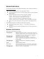
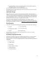
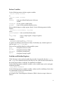
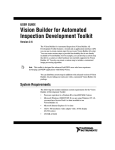
Figure below shows how IAS fits into your application development environment. IAS
assembles Itanium(TM) architecture assembly language files, generated by an assembly
language programmer, or a compiler. IAS generates an object file and, possibly, a
diagnostics listing. The diagnostics listing includes all the error and warning messages
IAS generates during assembly.
Application Development
See the Software Conventions and Runtime Architecture Guide for information on
combining C and assembly language code in one executable file.
Invoking IAS
To invoke IAS, use the command line:
ias [options] filename [options]
where:
options
Represent the command-line options described in the following
sections. You can place any option both before and after the file
name.
filename
Specifies an assembly language input file.
8
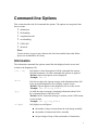
Command-line Options
This section describes the IAS command-line options. The options are categorized into
these sections:
yinformation
yfile handling
ycompilation model
yerror handling
yUNIX ABI
yadvanced
Note:
You do not have to type a space between the first letter and the letters that follow.
Spaces are included here for clarity.
Information
The information command-line options control the data displayed on the screen and
written to the diagnostics file.
[-H | -h]
IAS displays a short description of all the command-line options.
IAS then terminates. All other command-line options are ignored.
Default: Option descriptions are not displayed.
Example: ias -h
-N so
IAS does not place the sign-on message with information about IAS
in the generated diagnostics file or display it on the screen.
Default: Sign-on appears in the diagnostics file or on the screen.
Example: ias -N so my_file.s
-Q y
AS adds the sign-on message containing information about IAS to
the .comment section of the object file.
Default: In ELF format the message is written, and in COFF format
it is not written.
Example: ias -Q y my_file.s
-S nops
IAS displays several figures:
ythe number of nops it inserted into the code during assembly
ythe number of instructions before assembly
ythe percentage of nops of the total number of instructions
9
Default: Numbers are not displayed.
Example: ias my_file.s -S nops
-v
IAS prints IAS version information. Lists all libraries.
Default: The version information is not printed.
Example: ias my_file.s -v
-V
Prints the signon message, which is the default. Kept for backward
compatibility.
File Handling
The file handling command-line options define the input and output files.
-F OMF
This option defines the Object Module Format (OMF) of the object
file. Values for OMF are COFF32 for Windows NT, and ELF32 or
ELF64 when the targeted operating system is UNIX.
Default for Windows NT: COFF32
Default for UNIX: ELF64
Example: ias -F COFF32 my_file.s
-I pathname
AS adds pathname to an included input file search path list. This
option may be repeated to add more paths to the search list. The
paths are searched in the order listed.
Default: Searches for the file in the current directory only.
Example: ias -I c:\temp\my_path my_file.s
-o fname
IAS creates fname as the object file.
Default: input file name with an .obj extension.
Example: ias -o my_file.o my_file.s
By default IAS creates my_file.obj
Compilation Model
The compilation model options change the default compilation values.
-M ilp_model
10
This option defines the address model that IAS uses. Values for
ilp_model are:
ilp64 | lp64 | p64 – Default. Sets the address size to 64
bits. Integer and long sizes have no effect.
ilp32 – Sets the address size to 32 bits, relevant for COFF32
file format.
Default for Windows NT: ilp64
Example: ias my_file.s -M ilp64
-M byte_order This option sets the global default of the byte order of data
allocation statements. Values for byte_order are: le (littleendian) and be (big-endian). Use the .lsb and .msb directives to
set little or big-endian byte order for a specific section,
respectively.
Default: -M le
Example: ias -M be my_file.s
-N pi
IAS rejects privileged instructions. Use this option to ensure that
your code does not contain privileged instructions.
Default: Privileged instructions are accepted.
Example: ias -N pi my_file.s
-N
close_fcalls
IAS does not resolve global function calls. Instead you may want to
use another procedure by the same name that is defined elsewhere.
Default: Function calls are not resolved.
Example: ias -N close_fcalls my_file.s
-p 32
IAS enables defining 32-bit elements as relocatable data elements.
Kept for backward compatibility.
Error Handling
The error options define how IAS handles diagnostic messages.
-e fname
IAS creates fname as the diagnostics file. Error and warning
messages are sent to this file.
Default: Errors appear on the screen (stderr).
Example: ias -e my_err.txt my_file.s
-E max_num
IAS terminates when the number of errors IAS detects
reaches max_num.
Default: -E 30
Example: ias -E 3 my_file.s
-W warning_level
IAS displays different levels of warnings. Values for
warning_level are:
0 do not display warnings
1 display severe warnings
2 display warnings
3 display moderate warnings
4 display all warnings
11
x treat all warnings as errors and do not create object file if
any errors detected.
Default: 3
Example: ias -W 1 my_file.s
UNIX ABI Section
The following section describes command-line options specific to UNIX ABI, for
restricting the floating-point register range, and defining the kernel mode calling
convention. They must be used in conjuction with the -F ELF64 option.
-M rfp
AS restricts floating-point registers to the range F6 - F11.
This results in less register saves and restores when entering and
exiting the kernel, thereby reducing system time. Attempts to
use other floating-point registers cause an error.
Default: All floating-point registers can be used.
Example: ias -F ELF64 -M rfp my_file.s
-M const_gp
IAS sets the single global pointer (GP) model in the object file.
The kernel is then considered a single model, with one GP.
Default: No additional flags are set in the object file.
Example: ias -F ELF64 -M const_gp my_file.s
-M no_plabel
IAS sets the model in the object file to single GP and no
function descriptors (plabels). As with the -M const_gp
option, the kernel is then considered a single GP and doesn’t
use plabels.
Default: No additional flags are set in the object file.
Example: ias -F ELF64 -M no_plabel my_file.s
Advanced Section
The following section describes some advanced options that change the assembly mode
and permit virtual register allocation.
-X explicit
IAS changes the default initial assembly mode from automatic to
explicit.
Default: IAS assembles in automatic mode.
Example: ias -X explicit my_file.s
For more information on dependency violations see
Dependency Violations and Assembly Modes.
-X vral
IAS invokes the register allocation engine (virtual register
allocation), which allows the use of symbolic names instead of
12
actual register names. IAS creates a file with the suffix .vra
that lists the results of all register allocations.
Default: Vral is not active, so the Vral syntax is not recognized.
Example: ias -X vral my_file.s
-X unwind
IAS invokes the unwind generation utility. IAS builds unwind
information for all procedures in the file and ignores all unwind
directives.
Default: Unwind information is not generated.
Example: ias -X unwind my_file.s
-d debug
IAS creates Code View debug and line information for COFF32
objects. You can then use the symbolic debugger to single-step
on code lines and view symbols.
Default: No debug and line information is created.
Example: ias -F COFF32 -d debug my_file.s
-a
This command-line option indicates to IAS the default branch
indirect=br_tar target for indirect unannotated branches. It is relevant for virtual
get
register allocation. Values for br_target are:
exit exit is assumed to be the branch target
labels any label is assumed to be the branch target
Default: Exit is assumed.
Examples:
-ias -X explicit -a indirect=labels
my_file.s
or -ias -a indirect=exit my_file.s
-N us
This option enables an extended range of numbers, unifying both
signed and unsigned numbers. IAS accepts the numbers between
-64 and +127, as 7 bits long.
Default: The range of a 7-bit number is either between -64 and
+63, or between 0 and +127.
Example: ias -N us my_file.s
13
Dependency Violations and
Assembly Modes
This section describes dependency violations and how the Intel® Itanium(TM) assembler
(IAS) helps you avoid them in your code.
A violation of data dependency results from two instructions within an instruction group
accessing the same Itanium architecture resource, including resources that appear as
implicit operands. Dependency violations result in architecturally undefined behavior.
The assembler can detect and eliminate dependency violations that occur within
instruction groups, depending on its mode.
You can write code in explicit mode, thereby taking responsibility for bundling and stops
(;;). You can also use automatic mode where IAS automatically bundles your code ands
add stops to solve dependency violations. IAS allows you to mix modes in the one file.
For an explanation of bundles and stops, see the Intel® Itanium(TM) Architecture
Assembly Language Reference Guide or the Features section in this document.
When you choose to write code in explicit mode, IAS reports any dependency violations
it encounters. The easiest way to solve them is by inserting a stop. Some reports may not
be accurate, in which case you have at your disposal a range of annotations and
commands, explained later in this section.
For a complete description of data dependencies, see the Intel® Itanium(TM)
Architecture Software Developer’s Manual and the DVLoc for Scheduling Library.
This section includes:
yAssembly Modes
yMode Exmples
ySerialize and Memory Synchronization Instructions
yAvoiding False Reports
yPredicate Relation Analysis
Assembly Modes
IAS reads and processes assembly code in one of two modes: explicit or automatic. Use
explicit mode if you are an expert user with profound knowledge of Itanium(TM)
architecture and performance is important. Use automatic mode if you are a novice user
or performance is not important.
Automatic Mode
Automatic mode is appropriate for implementation of non-performance-critical code.
In this mode, you can write linear code without specifying bundle boundaries and without
worrying about architectural dependencies. IAS bundles the code and inserts stops (;;)
when needed. IAS ignores all your stops and dependency violations-related annotations.
14
Automatic mode is the default initial mode. The initial mode can be changed to explicit
mode with the command-line option -X explicit.
IAS issues an error if it encounters a curly bracket after the mode directive .auto.
IAS strives to insert a minimal number of stops.
Note:
In automatic mode, the assembler ignores the .pred.rel annotation.
Explicit Mode
Explicit mode is suitable when writing performance-critical code.
In this mode, you must avoid dependency violations by inserting stops and annotations in
the code. IAS checks the correctness of this code for dependency violations and returns
an error if it detects potential or certain problems.
You can set explicit mode in the following ways:
insert curly brackets ({,}) signifying bundle boundaries, while in default automatic
mode (Note that a curly bracket following a .auto directive causes an error.)
insert the directive .explicit
use the command-line option -X explicit, which changes the default mode from
automatic to explicit.
When you enter a new code section, IAS sets the mode back to the default.
If you write explicit code without bundle boundaries, IAS adds them. However, you are
responsible for stops and annotations. Annotations define relations between predicate
registers and other run-time values. See Avoiding False Reports.
Behavior of IAS
You can mix code from both modes in the one file. IAS provides you with several ways
to switch between the modes:
yuse the command-line option -X explicit
yuse the mode directives: .auto, .explicit, and .default
ywhen the initial default mode is automatic, allow IAS to switch according to code
syntax
If there are no bundles, IAS bundles the code, adds nops for correct bundling, and add
stops to avoid dependency violations.
The directives .explicit and .auto override the initial default mode for the current
code section.
The directive .default returns IAS to the initial default mode.
If IAS encounters a mode directive within an explicit bundle, IAS issues an error.
IAS automatically inserts a stop when it switches between modes.
For an explanation of how to write Itanium architecture code and avoid dependency
violations, see Avoiding False Reports.
15
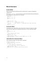
Mode Examples
Explicit Mode
When IAS encounters the following code in explicit mode, it registers a dependency
violation error.
The directive .default causes the mode to switch to the default initial mode defined in
the command line; which in this case is automatic.
.explicit
(p1)mov r1 = r4
;;;
(p2)mov r6 = r2
ldfps f4,f5 = [r4]
fabs f4 = f7 ; WAW error on f4
; IAS inserts a stop when the mode switches
.default
add r5 = 0, r7
Automatic Mode
In automatic mode, using similar code to the previous example, IAS ignores existing
stops and inserts stops between dependent instructions, as in the following example:
.auto
(p1)mov r1 = r4
;;;
; IAS ignores this stop
(p2)mov r6 = r2
ldfps f4,f5 = [r4]
; IAS inserts a stop to avoid WAW error on f4
fabs f4 = f7
Initial Default is Automatic Mode
In the following example, the default mode is automatic:
(p1)mov r1 = r4
; IAS inserts a stop here
(p2)mov r1 = r2
{ ; IAS inserts a stop here
; IAS treats this code as explicit
ldfps f4,f5 = [r4]
fabs f4 = f7 // write-after-write error
}
16
Serialize and Memory Syncronization Instructions
The serialize (srlz) and memory synchronization (sync) instructions have the
following constraints regarding instruction groups:
The serialize instruction (srlz.i or srlz.d) must be located in the
instruction group following the operation to be serialized.
Operations dependent on the serialization must be in an instruction group after the
srlz.i.
Operations dependent on the serialization must follow the srlz.d, but they can
be in the same instruction group as the srlz.d.
The sync.i instruction and previous Flush Cash operation must be in separate
instruction groups.
For safety’s sake, IAS in automatic mode inserts stops before srlz.d and sync.i
instructions, and both before and after the srlz.i instruction. In explicit mode IAS does not
indicate errors when stops are missing.
y
y
y
y
Avoiding False Reports
In some cases, when in explicit mode IAS falsely reports a dependency violation. IAS
cannot calculate all the properties of the code when information is lacking.
The simplest way to avoid false register dependency errors is by using stops. Place a stop
(;;) between the two instructions causing the violation dependency. This approach is
simple and always works, but might result in performance degradation.
Use the following annotations to assist IAS in analysis of dependency violations to solve
false reports, without sacrificing performance:
.pred.rel
.reg.val
y
y
y.mem.offset
Note:
Annotations supply additional information that assists IAS’ analysis of apparent
dependency violations.
For a description of annotations’ syntax, see the Intel® Itanium(TM) Architecture
Assembly Language Reference Guide.
The examples that follow show some typical situations where adding annotations helps
avoid false reports.
17
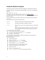
Predicate Relation Analysis
IAS analyzes predicate relations to determine dependency violations between pairs of
predicated instructions. The following example displays a write-after-write dependency
violation:
(p1) add r5 = 8, r6
(p2) add r5 = r7, r0
To understand how IAS performs predicate analysis, see Predicate Analysis.
The compare instructions define predicate register values and may result in definition of
predicate relations.
To pass on information about predicate relations, use the predicate relation annotation
.pred.rel.
The annotation .pred.rel takes the following forms:
“mutex”
The mutex form defines a mutually exclusive relation.
“imply”
The imply form defines an implication relation.
“clear”
The clear form removes mutex and imply relations, as described
below.
When conflicting instructions follow an entry point, IAS ignores
all existing predicate relations defined before the entry point.
An entry point is any of the following:
a label, whether local, global, or temporary
the address of the bundle following a br.call instruction
the target of a direct branch
Use the predicate relation annotation to define the relations between predicates and
prevent dependency violation errors.
This section includes:
Compare Instructions
Mutex Form of the .pred.rel Annotation
Implication Form of the .pred.rel Annotation
y
y
y
y
y
y
yClear Formof the .pred.rel Annotation
yMutex Relation Not Created with a Single Compare
yInstructions Separated by a Predicate Branch
ySafe Across Calls
yIndirect Access to Register File
yst8.spill and ld8.fill in the Same Instruction Group
18
Compare Instructions
The compare instructions (cmp, tbit, fclass, and fcmp) define predicate values.
They precede the predicated instructions. The compare instructions indicate to the
assembler that the named predicate registers are mutually exclusive. They override any
other defined mutex relations between the destination predicate registers and other
predicate registers.
These examples all show the use of the cmp instruction for simplicity. Use the tbit,
fclass, and fcmp instructions for the same effect.
In the example below, the cmp instruction states that P1 and P2 cannot both be true at the
same time, thereby avoiding a violation dependency error.
mp.lt p1, p2 = r13, r0;;
(p1) dd r5 = 8, r6
(p2) dd r5 = r7, r0
The cmp instruction overrides the mutex relation between the destination predicate
registers and all the other predicate registers. For example:
mp.lt p1,p2 = r13,r0;;
; p1 and p2 are mutually exclusive
mp.lt p1,p3 = r12,r11;;
; the mutex relation between p1 and
; p2 is destroyed by cmp
(p1) dd r5 = 8, r6
(p2) add r5 = r7, r0 // WAW error
Mutex Form of the .pred.rel Annotation
Format: .pred.rel “mutex” p1, p2 [,&ldots;]
where
p1, p2 ... are predicate registers
.pred.rel “mutex” informs the assembler that only one of the specified predicate
registers is true, or all are false. For example:
.pred.rel “mutex”, p1, p2, p3
; p1, p2, and p3 are mutually exclusive or all zero
(p1)add r5 = 8, r6
(p2)add r5 = r7, r0
(p3)add r5 = r14, r0
The mutex form is unordered, meaning that the order in which the predicates appear is
not important.
The mutex form does not override predefined mutex relations between the destination
predicate registers and other predicate registers. For example:
.pred.rel “mutex”,p1,p2
.pred.rel “mutex”,p1,p3
.pred.rel “mutex”,p2,p3
; p1,p2 and p3 are mutex
(p1)mov r4=r5
(p2)mov r4=r6
(p3)mov r4=r7 // no WAW error is reported
19
Implication Form of the .pred.rel Annotation
Format:
.pred.rel “imply” p1, p2
where
p1, p2DUHSUHGLFDWHUHJLVWHUV
The .pred.rel annotation of the form “imply” informs the assembler that if the first
predicate is true then the second one is also. No assumptions are made when the first
predicate is false; the second predicate’s value is undetermined. The implication form is
ordered, meaning that the order of the predicates is important.
In the next example, if P1 is true, then P2 is also true.
.pred.rel “imply”, p1, p2
(p1)mov r4=r5
(p2)br.cond.dpnt.few b0
mov r4=r5
; WAW on r4 is not reported as p1 implies p2
The implication form is a transitive relation. If P1 implies P2 and P2 implies P3, so P1
also implies P3.
Clear Form of the .pred.rel Annotation
The .pred.rel annotation of the form “clear” erases predicates relations. If you
specify the predicate register P1, IAS erases all the mutex relations containing P1, and all
the implication relations in which P1 is the implicating predicate register. If you do not
specify any predicate registers, IAS takes this as a shortcut to naming all the predicate
registers.
Format:
.pred.rel “clear” [p1[,p2[,&ldots;]]]
where
p1, p2 are predicate registers
For example:
.pred.rel “clear” p1 ; clears all the p1 relations
.pred.rel “clear”
; clears all predicate relations
The following example uses both mutex and implication relations. The form “clear”
has different effects depending on the relations.
.pred.rel “mutex”,p1,p2
.pred.rel “mutex”,p3,p1
.pred.rel “imply”,p1,p4
.pred.rel “imply”,p5,p1
.pred.rel “clear”,p1
;
; clears the two mutex relations
; and the first implication form
;
(p1) mov r1=r2
; => WAW on r1 is reported
(p2) mov r1=r2
;;
20
(p1) mov r2=r3
(p3) mov r2=r3
; => WAW on r2 is reported
;;
(p1) mov r3=r4
(p4) br.cond.sptk.few b0
mov r3=r4
; => WAW on r3 is reported
// WAW would not have been reported if p1 -> p4
;;
(p5) mov r4=r5
(p1) br.cond.sptk.few b0
mov r4=r5
; WAW is not reported.
; p5 -> p1 is still valid
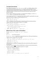
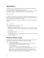
Mutex Relation Not Created with a Simple Compare
In the following code, P1, P2, and P3, are mutex since R10 can have only one value at a
time. IAS fails to interpret the inherently mutex relation and reports three WAW
dependency violations.
cmp.eq p1=1,r10
cmp.eq p2=2,r10
cmp.eq p3=3,r10;;
(p1) mov r4=r1
(p2) mov r4=r2
(p3) mov r4=r3
To resolve this, use the .pred.rel annotation of the “mutex” form:
cmp.eq p1=1,r10
cmp.eq p2=2,r10
cmp.eq p3=3,r10;;
.pred.rel “mutex”,p1,p2,p3
(p1) mov r4=r1
(p2) mov r4=r2
(p3) mov r4=r3
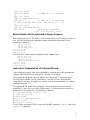
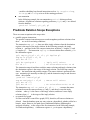
Instructions Separated by a Predicated Branch
In the following example, there are no dependency violations due to the unconditional
compare. The instructions are numbered #1 through #6 for clarity.
The apparent WAW on R1 can never happen since instruction #2 and instruction #5
never execute in parallel. That is, instruction #2 executes (P2 true) implying that
instruction #4 executes (P2 implies P1), and the code execution branches to L without
reaching instruction #5.
The apparent WAW on R2 can only happen if instruction #4 does not execute and
instruction #6 does. Since execution of instruction #6 (P3 true) implies execution of
instruction #4 (P3 implies P1), the WAW never happens.
#1 (p1) cmp.eq.unc p2,p3=r1,r2;;
#2 (p2) mov r1=r10
#3 mov r2=r11
#4 (p1) br.cond.dpnt.few L
#5 mov r1=r12
#6 (p3) mov r2=r13
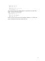
To avoid false reporting of WAW errors on R1 and R2, insert the “imply” form of the
.pred.rel annotation:
21
(p1) cmp.eq.unc p2,p3=r1,r2;;
.pred.rel “imply”,p2,p1
; if p2 is true, p1 is true
.pred.rel “imply”,p3,p1
; same as above, with p3
(p2) mov r1=r10
mov r2=r11
(p1) br.cond.dpnt.few L
mov r1=r12
(p3) mov r2=r13
Safe Across Calls
The annotation .pred.safe_across_calls allows predicate relations to be retained, even
after calls to other procedures. Use this annotation to specify which predicates should
have their relations preserved. The scope of the annotation is within the current procedure
or module.
You can specify several individual predicates and a range of predicates, all in the one
statement.
Format:
.pred.safe_across_calls p1, p2, ...
where P1, P2, etc. can represent specific predicate registers or ranges of registers.
In the following example, if the .pred.safe_across_calls annotation is not included,
IAS reports a dependency violation between two last instructions, as procedure foo may
change the predicate values.
.pred.safe_across_calls p2-p6, p10, p11
.pred.rel “mutex“, p3, p4
br.call b1=foo
(p3) mov r5=r32
(p4) add r5=8, r32
To clear the predicate relations defined by the annotation .pred.safe_across_calls, use
as follows:
.pred.safe_across_calls ”clear”
Indirect Access to Register File
The existence of dependency violations may depend on general register values; for
example, when accessing register files indirectly. In the following example, two different
registers are accessed indirectly. IAS does not have information about the values of the
index registers, so it reports a WAW error on pmd.
mov
mov
mov
mov
r1=2
r2=4;;
pmd[r1]=r11
pmd[r2]=r12
To resolve this, use the .reg.val annotation to inform IAS that the two writes to pmd
access different registers:
mov r1=2
mov r2=4;;
.reg.val r1,2
mov pmd[r1]=r11
.reg.val r2,4
mov pmd[r2]=r12
22
st8.spill and ld8.fill in the Same Instruction Group
The instruction st8.spill writes to a specific bit in the UNAT application register,
according to the accessed address in memory. The instruction ld8.fill reads a
specific bit of the UNAT application register, according to the accessed address in
memory. For more details see the Intel® Itanium(TM) Architecture Software Developer’s
Manual.
IAS cannot know the address of the accessed memory, so where no annotations are
provided, it reports the following dependency violations:
• WAW for every pair of st8.spill instructions
• RAW for every ld8.fill instruction that appears after st8.spill in the same instruction
group
In the following code, one WAW and two RAW dependency violations are reported,
although the code assures that the accessed UNAT bits are different:
add r2=r1,8
add r3=r1,16;;
st8.spill [r1]=r11
st8.spill [r2]=r11
ld8.fill r12=[r3]
To avoid this false report, use a .mem.offset annotation before each st8.spill and
ld8.fill instruction. The annotation must state the memory address location relative
to some local arbitrary memory region, such as the current stack:
LOCAL_STACK_INDEX=0
add r2=8,r1
add r3=16,r1;;
.mem.offset 0,LOCAL_STACK_INDEX
.st8.spill [r1]=r11
.mem.offset 8,LOCAL_STACK_INDEX
.st8.spill [r2]=r11
.mem.offset 16,LOCAL_STACK_INDEX
.ld8.fill r12=[r3]
For further explanation of the .mem.offset annotation, see the Intel® Itanium(TM)
Architecture Assembly Language Reference Guide.
To understand how IAS performs predicate analysis, see Predicate Analysis.
23
Features
This section describes the following Intel® Itanium(TM) Assembler (IAS) features:
yAssembly Language Features in brief, which are fully defined in the Intel®
Itanium(TM) Architecture Assembly Language Reference Guide
yComplementary Features specific to the Intel© Itanium architecture assembly
tool.
Assembly Language Features
y
y
y
y
y
y
y
y
y
y
IAS supports these Itanium(TM) architecture assembly language specification features:
Instruction Set
Bundling
Instruction Groups
Data Allocation
Assembly Language Directives
64-bit Address Space
Alignment
Assignment Statements
Aliasing
Arithmetic Expression Handling
The following sections provide a short description of these features. See the Intel®
Itanium™ Architecture Assembly Language Reference Guide for the full explanation of
these features.
Instruction Set
IAS supports the full Itanium(TM) architecture instruction set, defined in the Intel®
Itanium(TM) Architecture Software Developer’s Manual.
Bundling
Itanium(TM) processors execute instructions in bundles. A bundle contains up to three
instructions, and an associated template. The template defines which type of execution
unit processes each instruction in the bundle.
IAS enables several levels of bundle definition:
yExplicit bundling and template definition. You define the bundle boundaries and
the bundle template.
yExplicit bundling without template definition. You define the bundle boundaries;
IAS chooses the best fitting bundle template.
24
yImplicit bundling. IAS chooses bundle boundaries and the bundle template by
selecting the optimal code size arrangements.
At all the bundle definition levels IAS inserts required NOPs.
The bundling feature is fully defined in the Intel® Itanium(TM) Architecture Assembly
Language Reference Guide.
Instruction Groups
Itanium(TM) processors execute several instructions in parallel. Instructions that are
allowed to execute in parallel are organized in instruction groups. An instruction group is
a set of consecutive instructions that should have no interdependencies. The instruction
group is terminated by a stop (;;). IAS supports explicit stops as defined in the Intel®
Itanium(TM) Architecture Assembly Language Reference Guide.
IAS checks for data dependencies in instruction groups. An example of a data
dependency is a write instruction following a read instruction to the same register. For
more details on dependency violations, see Dependency Violations and Assembly Modes.
Data Allocation
IAS enables allocating and initializing space in memory. IAS supports these data types:
yintegers
yfloating-point numbers
ystrings
1, 2, 4, or 8 bytes long
4, 8, 10 or 16 bytes long
up to 1024 bits long
Data allocation is fully defined in the Intel® Itanium(TM) Architecture Assembly
Language Reference Guide.
Assembly Language Directives
IAS supports all Itanium architecture assembly language directives except local label
directives, which are described in the Intel® Itanium(TM) Architecture Assembly
Language Reference Guide. The supported directives include the following operations or
information:
ysection control
ysymbol control
yfile inclusion
ybundle template selection
ydebug information
yunwind information
25
64-bit Address Space
IAS supports 64-bit address space.
When using the -ilp32 command-line option (this is the default for COFF32 output
file format), symbolic addresses are limited to 32-bit allocation (data4). IAS displays an
error message when you attempt to use relocatable expressions at 64-bit allocations
(data8).
This feature is fully defined in the Intel® Itanium(TM) Architecture Assembly Language
Reference Guide.
Alignment
By default, IAS aligns bundles on 16-byte boundaries, and data elements according to
their size.
IAS aligns each section according to the largest alignment request in the section.
Bundles, data elements, or an .align directive create alignment requests.
The object file format limits section alignment. COFF32 object file format limits section
alignment boundaries to 8 KB. The actual limitation depends on the linker alignment
policy. See the Microsoft* Developer Studio, Visual C++* User's Guide, and LINK
Reference for more information on the linker.
To disable automatic alignment in data allocation statements, add a .uaFRPSOHWHU to
the data allocation statement. For example:
data8.ua 0x855
Alignment is fully defined in the Intel® Itanium(TM) Architecture Assembly Language
Reference Guide.
Assignment Statements
Assignment statements enable the programmer to define a symbol by assigning it a value.
This value may be a reference to another symbol, register name, or expression. See the
Intel® Itanium(TM) Architecture Assembly Language Reference Guide for more
information.
Aliasing
IAS supports aliasing of symbol names and section names. Aliasing is implemented as
follows:
symbol names
section names
Aliased by an .alias directive. The alias name appears in the
symbol table of the output file.
Aliased by a .secalias directive. The alias name appears in the
symbol table of the output file. See the .secalias Directive section
for more information.
Aliasing is fully defined in the Intel® Itanium(TM) Architecture Assembly Language
Reference Guide.
26
Arithmentic Expression Handling
IAS supports the use of arithmetic expressions for constants and addresses, using
standard arithmetic notation. Arithmetic expressions can include symbols, numeric
constants, and operators.
IAS supports expressions that access linker tables during run-time, through the use of
several link-relocation operators. See the Intel® Itanium(TM) Architecture Assembly
Language Reference Guide for more information on link-relocation operators.
Input file constants are internally represented as signed 128-bit numbers. IAS makes all
integer calculations with 128-bit precision, and floating point calculations (real numbers)
in extended precision (long double).
Complementary Features
IAS has several additional features not documented in the Intel® Itanium(TM)
Architecture Assembly Language Reference Guide:
IA-32 jmpe Instruction
instenc Pseudo-instruction
String Equation
.secalias Directive
Line Information for Debugging Tools
# line Support
Predefined Symbols
Virtual Registers Allocation
Unwind Information Generation
y
y
y
y
y
y
y
y
y
27
IA-32 jmpe Instruction
IAS supports IA-32 to Itanium(TM) architecture transition instructions (jmpe) from
within Itanium architecture assembly language files. When you assemble an Itanium
architecture file with a jmpe instruction, IAS creates an IA-32 jmpe instruction, enabling
the transition from IA-32 code to Itanium architecture code.
The following directives are available:
jmpe.next
Jumps to the next 16-byte aligned address.
jmpe.abs address Jumps to the specified address, as a number
or as a relocatable expression.
jmpe.IA-reg32
Takes an indirect jump to the address
specified in the IA-32 register. For example:
jmpe.eax.
instenc Pseudo-instruction
This pseudo-instruction enables you to enter a 41-bit immediate number to a slot in a
bundle. This immediate number may be recognized by the Itanium(TM) processor as an
instruction. However, IAS does not check that the immediate number corresponds to a
valid Itanium architecture instruction.
This pseudo-instruction is useful when you want to create executable code containing
instructions that your current assembler version may consider illegal.
Syntax
instenc.completer imm41
where:
completer
Defines the role of the instruction in the bundle.
These are this instruction’s completers:
a ALU instruction
m memory instruction
i integer instruction
b branch instruction
f floating-point instruction
imm41
28
Is the immediate number corresponding to an
Itanium instruction.
Example
This example inserts a floating-point instruction into the bundle.
{
add r1 = r2, r3
instenc.f 0x1F423C02DA9
}
String Equation
The equation statement (==) that equates a symbol to a value or a register, can also
equate a symbol to a string. For example:
save_file_name == @filename
RU
source_file == "my_file.s"
You cannot forward-reference a string equation statement.
.secalias Directive
The .secalias directive defines an alias for a section name. .secalias does for
section names what .alias does for symbol names. See Aliasing section for more
information.
Within the input file you reference the section by the section name. In the output file the
section is referenced with its alias. Typical use of this directive is to identify a section
with a name that is not a legal assembly identifier.
Note
You must define the section before you use .secalias to alias it.
Syntax
.secalias section_name, "output-section_name"
where:
section_name
Is the name of the section in the input file.
outputsection_name
Is the name of the section in the output
file.
Example
This example shows the use of the .secalias directive to alias a section name.
.section
. . .
sec1, "ax",
"progbits"
.secalias
. . .
sec1, "sec++"
.text
.xdata
. . .
sec1, 5
29
Line Information for Debugging Tools
Debug directives create line information used to create debug information in the object
file. Each line information directive creates a debug record. The debug record points to
the position of the code generated by the instruction following it. Two debug records
cannot point to the same location. Therefore, make sure there are lines of code between
two debug directives.
The line information reference in the debug record refers to the exact instruction slot in
the bundle.
If you use the -d debug command-line option, IAS ignores the .bf, .ln, and .ef
directives.
Use this general template to produce line information:
.file "source-file-name"
...
.proc entry [,...]
...
entry:
...
.bf entry, source-line-no
;
; prologue code
;
.ln source-line-no
; assembly code
.ln source-line-no
;
; assembly code
;
...
...
.ln source-line-no
;
; assembly code
;
.ef entry, source-line-no, procedure-size
;
; epilogue code
;
.endp [entry]
#line Support
The #line directives define the line number of the next code line, and can also replace
the file name for the object file. You can explicitly enter the #line directives, or they
may be inserted by the preprocessor.
The #line definition impacts the diagnostic messages and assembly-level line
information created when the -d line option is specified in the command-line option.
See Compilation Model for more information.
30
These are the #line directives IAS recognizes:
#line line-no
IAS treats the next line as the line-no line in the
current file, regardless of the serial count.
#line line-no "filename"
IAS treats the next line as the line-no line in
"file-name"; this file name replaces the previous
object file name.
This directive may also contain a comma between the
operands.
Predefined Symbols
IAS provides three predefined symbols. Use them in the assembly language file:
@line
is an integer specifying the current line number.
Usage example:
data8 @line
@filename is a string specifying the current file name.
Usage example:
stringz @filename
@filepath is a string specifying the current path and filename.
Usage example:
stringz @filepath
Virtual Registers Allocation
Virtual registers allocation (Vral) allows use of symbolic names instead of register
names. This feature replaces registers or groups of registers with meaningful names,
making code
ysimpler to write
yfaster to read
yeasier to maintain
When VRAL is activated, the assembler analyzes control flow and data flow, builds life
ranges for each register, and replaces symbolic names with the user-allocated registers.
With one directive, VRAL can assign one name to a group of registers, allowing the
assembler to handle the use of individual registers within the group. VRAL is then
responsible for ensuring safe reuse of registers.
To allocate symbolic names to registers, use these directives:
y.vreg.allocatable
y.vreg.safe_across_calls
To declare register variables, use these directives:
y.vreg.var Family, Xcounter
y.vreg.family LocalIntFamily,
reg_range
31
To undefine or redefine variables, use these directives:
y.vreg.undef
y.vreg.redef
Xcounter
Xcounter
The following annotations are useful when using Vral:
y.br.target annotation
y.entry annotation
y.bank switch annotation
This section includes:
yAllocate Registers
yDeclare Variables
yUndefine and Redefine Registers
yBranch Target Annotation
yRegister Value Annotation
yBank Register Annotation
Allocate Registers
The .vreg.allocatable directive assigns registers for allocation, thereby making them
available for VRAL from this point in this procedure. There can be more than one
allocation directive in each procedure. Values of these registers are not ensured preserved
across calls. This directive has the following syntax:
.vreg.allocatable reg_range
where
reg_range can be a single register, a range of registers, or both.
In the following example, integer registers 14 through 26, and register 30 are assigned:
.vreg.allocatable r14-26, r305
Alternatively, the .vreg.safe_across_calls directive informs the assembler that the
named registers are preserved across calls. This directive assurs the assembler that
branches to external procedures following this directive do not access or corrupt the
named registers. The directive has the following syntax:
.vreg.safe_across_calls reg_range
where
reg_range is not restricted to the registers allocated in the .vreg.allocatable directive.
Example:
.vreg.safe_across_calls f16, f18-f21
32
Declare Variables
Use the following syntax to declare register variables:
.vreg.var Family, Xcounter
or
.vreg.var predef, Xcounter
where
Family
Is the user-defined family name of the new
variable.
Xcounter Is a new register variable name.
predef
Is one of four predefined families, below.
Each variable belongs to a single register family. Use the following syntax to define
families:
.vreg.family LocalIntFamily, reg_range
where
LocalIntFamil Is the user-defined family name.
y
reg_range
Can be a single register, a range of registers,
or both.
Examples:
.vreg.family MyLocalFamily, loc0-loc3
.vreg.family FpUsedRegisters, f17-f25
A register may belong to more than one family. Each family may contain registers of
only one type (int, float, etc.).
There are four predefined families in the assembler syntax:
@int
all registers from r1 to r127
@float
all registers from f1 to f127
@branch
all registers from b0 to b7
@pred
all registers from p1 to p63
Undefine and Redefine Registers
VRAL directives can be used only within the procedure, between the directives .proc
and .endp. The variables declared by the directives are valid from their declaration till
the end of the procedure or until they are undefined or redefined.
Use the following syntax to undefine variables, so the variable names can be used again
within the procedure:
.vreg.undef Xcounter
Use the following syntax to redefine variables, with no need for undefining. Notice there
is no opportunity to specify a different family:
.vreg.redef Xcounter
An example of the Virtual Registers Allocation (VRAL) directives usage is shown as
follows.
33
Virtual Registers Allocation Example
.proc foo
.vreg.allocatable r19-r21, r27
.vreg.safe_across_calls r20, r21, p5-p6
.vreg.var @pred, HL1, L1H, HL2, L2H, HX, XH
.vreg.family MyGlobals, r19-r20
.vreg.var MyGlobals, High, Low1, Low2
foo::
alloc loc0 = 3,1,1,0
ld8 High = [in0]
ld8 Low1 = [in1];;
cmp.gt HL1, L1H = High, Low1
(L1H) br.cond.sptk.few LE
sub out0 = High, Low1
GT: add r22 = 32, r5;;
; ...
END:
cmp.eq HX, XH = High, r22
(HX) br.call.spnt.many rp = bar;;
(XH) st8 [r23] = High
br.ret.sptk.clr b2
LE: ld8 Low2 = [in2] ;;
cmp.gt HL2, L2H = High, Low2
(HL2) sub out0 = High, Low2
(HL2) br.cond.sptk.few GT ;;
mov out0 = 0
; ...
br.cond.sptk END
.endp foo
Branch Target Annotation
The branch target annotation .br.target precedes an indirect branch and explicitly
provides the assembler with the branch target address for the branch instruction. This
annotation applies only to the branch instruction that immediately follows the annotation.
The .br.target annotation has the following syntax:
.br.target			target1[=prob1] [,target2[=prob2]...]
where:
target Specifies the targets of the next indirect branch
instruction. May be one of the following:
prob
A real number that indicates the probability that the
associated branch target is taken.
The following examples illustrates a branch target annotation.
Using the Branch Target Annotation 1
.br.target a=0.6, b, @fallthrough=0.2, @external=0.1
Using the Branch Target Annotation 2
br.target Target002
(p4)br.cond.sptk.many.b1
where
34
Target002 Is the name of a label in the procedure.
Register Value Annotation
The register value annotation .reg.val informs the assembler of the contents of a register.
It is used for dependency violations detection.
The annotation has the following syntax:
.reg.val reg, val
where:
reg
Represents any integer register from r0 to
r127.
val
Is any real number.
Example below illustrates a .reg.val annotation.
Using the Register Value Annotation
.reg.val r5,3
Bank Register Annotation
By default, the assembler assumes that the register bank at the entry point is bank 1. To
overwrite this default use the .bank directive. It is necessary only for procedures that
contain a bsw instruction, for VRAL.
This annotation makes it clear to the assembler to which bank of registers the instructions
refer.
The .bank switch annotation has the following syntax:
.bank
n
where:
n represents 0 or 1.
Example that follows illustrates a .bank annotation.
Using the Bank Switch Annotation
.proc A
A:
.bank 0
...
bsw.1
...
bsw.0
...
.endp
//entry annotation
Unwind Information Generation
IAS applies static analysis to procedure code to automatically generate unwind records.
Use this feature when a procedure as an intermediate element must provide safe
propagation of the stack unwinding process from the called function to the unwind
handler in the caller procedure.
The assembler builds unwind information for all procedures in the file, starting from the
procedure’s first entry point and continuing through to .endp.
When the static analysis is not complete; for example, an indirect branch is
35
unaccompanied by branch target annotation, IAS sends a warning message and then
attempts to simplify the analysis by assuming that the procedure has one prologue and
multiple epilogues. This approach works in most cases. If this is not successful, IAS
issues an error message.
The unwind generator is based upon the Itanium(TM) architecture software conventions.
See the Software Conventions and Runtime Architecture Guide. Invoke unwind
generation using the -X unwind command-line option. When you use this flag, IAS
ignores all unwind directives and issues a warning.
36
Diagnostic Messages
When IAS encounters suspicious or incorrect input, or fails at some operation, it provides
a diagnostic message. You can receive the diagnostic messages either on the screen, or
send them to a file. See Error Handling for more information.
This section describes the syntax of diagnostic messages, and describes the diagnostic
messages in numeric order.
Note:
IAS displays diagnostic messages according to the order of their corresponding
lines in the source code. This order is not necessarily the order in which they were
detected. Therefore, a diagnostic message of the derivative error may appear
before the diagnostic message from the original error.
This section includes:
yDiagnostic Message Types
yDiagnostic Message Syntax
yFatal Error Messages
yError Messages
yWarning Messages
Diagnostic Message Types
IAS sends these types of diagnostic messages:
fatal error messages
IAS detected incorrect input that causes termination. IAS does
not produce an object file. Fatal error message numbers have
this format: A1xxx.
error messages
IAS detected incorrect input. Execution continues. However,
IAS does not produce an object file. Error message numbers
have this format: A2xxx.
warning messages
IAS detected legal, but suspicious input. Execution continues
and IAS produces an object file. Warning message numbers
have this format: A3xxx.
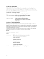
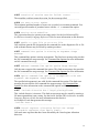
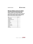
Diagnostic Message Syntax
A diagnostic message specifies the location of the error, its type, and a short description
of the error, as described below and shown in the Figure that follows the table.
37
Location
The file name and line number information helps to locate the
exact part of the code that needs correction. In some cases the
location shows the detection of a derivative error.
Severity
This information indicates the severity of the error.
Message number
IAS message numbers are prefixed by an A. Use the message
number to locate its description.
Message text
This text provides a one line explanation of the incorrect or
suspicious input.
Figure below shows an example of an error message, and specifies the message elements.
Diagnostic Message Syntax Example
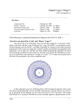
Diagnostic Message Format
This is the format of the diagnostic message descriptions:
Message Number Text of the message
Additional description of the message.
Fatal Error Messages
This section describes fatal error messages. A fatal error causes immediate IAS
termination without creating an object file. These are the fatal error messages IAS may
display:
A1012 cannot open input file file
IAS could not open this file. This fatal error message is usually due to an incorrect file
name or path.
A1013 cannot open input file file included from file (line)
IAS could not open this file. This fatal error message is usually due to an incorrect file
name or path in the .include directory.
A1014 cannot open registers allocation log file file
IAS could not open the file that lists the results of virtual registers allocations. Check that
the file name with a suffix .vra is not in use. Delete any read-only files with the suffix
.vra.
38
A1015 creation of section section failed: reason
The assembler could not create the section, for the reason specified.
A1018 too many errors: number
The maximum permitted number of errors was exceeded, so execution terminated. You
can configure the number of permitted errors with the -E n command-line option.
A1020 section stack underflow
The .popsection directive operates on an empty stack. See the Intel® Itanium(TM)
Architecture Assembly Language Reference Guide for more information on this directive.
A1021 unable to open file as an error file
IAS could not open the file designated in the command-line as the diagnostics file. A file
with an identical name may be locked by another procedure.
A1022 command-line option is missing an argument Usage
message
This command-line option is missing an argument. This fatal error message also provides
the IAS command-line usage message. See Command-line Options for more information
on IAS command-line usage.
A1025 unknown command-line option option Usage message
IAS does not recognize this command-line option. This fatal error message also provides
the IAS command-line usage message. See Command-line Options for more information.
A1026 option command-line option is incompatible with subargument sub-argument usage message
The specified sub-argument is not valid for this command-line option. This fatal error
message also provides the IAS command-line usage message. See Command-line
Options for more information on the command-line options and their sub-arguments.
A1027 .include directive has illegal placing/format
This .include directive is incorrect. This fatal error message may be caused by entering a
file name operand that is not a string. See the Intel® Itanium(TM) Architecture Assembly
Language Reference Guide for more information on this directive.
An example of code that generates this message:
.include data.s
A1050 virtual register allocation failed: not enough
allocatable registers from family family
IAS needs more registers than have been allocated by the virtual register allocation
directives.
39
A1099 nesting level (number) of .include directive exceeded
for included file file
This .include directive is nested beyond the IAS nesting limit. IAS allows up to 20
nested levels.
Error Messages
This section describes the error messages. An error does not terminate IAS execution.
However, it does prevent object file production. These are the error messages IAS may
display:
A2000 too long symbol name
The symbol name may not be longer than 4096 characters.
A2023 there should be a prologue region in the function
This directive requires a prologue code region in the function.
A2024 the personality routine is not defined for the
language specific data
This directive requires defining a personality routine definition before the directive. Add
a .personality directive before the .handlerdata directive. See the ,QWHO,WDQLXP70
$UFKLWHFWXUH$VVHPEO\/DQJXDJH5HIHUHQFH*XLGH for more information on these
directives.
A2025 directive ".proc" is not allowed within section
".xdata."
You cannot put a .proc directive in an .xdata section.
A2026 section switch is not allowed within handlerdata
region
You cannot switch sections in a handlerdata region.
A2027 debug directive points outside the function
An operand of the debug directive points outside the current function.
A2028 directive is allowed only within an explicit bundle
This directive is legal only when specified within an explicit bundle. Place this directive
in between the two curly brackets "{"DQG"}".
A2029 directive is not allowed within an explicit bundle
This directive is not legal when specified within an explicit bundle. Make sure this
directive is not placed between the two curly brackets "{" and "}".
40
A2030 misplaced or missing ’}’
There is a curly bracket mismatch. Check preceding bundle’s curly bracket structure.
A2031 Unclosed parenthesis at start-of-statement
This statement starts with an open parenthesis token "(". However, the close parenthesis
")" is missing. This statement may have an unclosed qualifying predicate.
A2032 Unexpected element instead of predicate register
Something other than a predicate register is specified in the location reserved for the
predicate register.
An example of correct usage:
(p62) add r2 = r3, r6
In this example P62 is the predicate register.
An example of code that generates this error message:
(p64) add r2 = r3, r6
The predicate registers range is P0 - P63.
A2033 Unexpected element instead of tag
Something other than a tag is specified in the location reserved for tags.
An example of correct usage:
.save pr, r3, T
[T:] mov r3=pr
A2034 Unexpected token at end-of-statement: token
The statement ends with an unexpected token. Delete or change the token.
An example of code that generates this error message:
add r1=r2,r3,
A2035 invalid token: token
This token is invalid.
An example of code that generates this error message:
add r1=r2,r3!
A2036 illegal usage of reserved register: register
This register is a reserved register. Use a different register.
An example of code that generates this error message:
mov r5=ar8
A2037 Unexpected token at start-of-statement: token
This token is not valid at the start of the statement. Delete or move the token.
An example of code that generates this error message:
)add r1=r2,r3
41
This error message may also be the result of a misspelled mnemonic. An example of a
misspelled mnemonic that generates this error message:
br.cal b5=L
L:
A2038 symbol/section already aliased as name
This symbol or section cannot be aliased at this stage, since it is already aliased as
something else.
A2039 label already defined: label
This label cannot be defined at this stage, since it is already defined elsewhere. Use a new
label for this definition.
A2040 Unexpected token token
The specified token is not expected in this location.
A2042 symbol symbol for definition type is already defined
This symbol is already defined elsewhere. Use a new name for this definition.
An example of code that generates this error message:
L:
L=8
A2047 unexpected character character in string hexa-escapesequence
The hexa-escape sequence contains an unexpected character. Hexa-escape sequences can
contain digits 0-9 and/or letters A-F.
Examples of correct hexa-escape sequences are: \xa, or \xD9.
A2048 illegal bundle brace in automatic mode
IAS encountered a curly bracket ({) or (}) while in automatic assembly mode. Automatic
mode was specified with the .auto directive.
A2049 relocatable expressions based on symbols symbol and
symbol from different sections cannot be subtracted
These relocatable expressions are from different sections. To subtract two relocatable
expressions, they must originate in the same section.
A2050 cannot subtract relocatable expressions based on an
external or common symbol
To subtract two relocatable expressions, they must be based on symbols defined in the
same section. One or both of these relocatable expressions is probably based on an
external or common symbol.
42
A2051 wrong operand parenthesis structure
The operand parenthesis structure is incorrect.
An example of code that generates this error message: nop ((5+3)
A2052 wrong operand bracket ’[‘’]’ structure
The operand bracket structure is incorrect.
An example of code that generates this error message:
ld8 r6 = [r4]]
$
illegal argument [argument-type] for unary-operator
operator, or misplaced/missing operator
This argument-type is not legal for the specified unary operator.
An example of code that generates this error message:
and r3=r2,+r5
A2056 missing arguments for binary-operator: operator
This binary-operator is missing arguments.
An example of code that generates this error message:
mov rr[] = r6
A2057 illegal argument-pair [left: argument right: argument]
for binary-operator operator, or misplaced/missing operator
These arguments cannot operate together. A typical mistake causing this error message is
the use of a binary operator with at least one operand that is not valid for this operator.
An example of code that generates this error message: or r4 = dbr[f4], r6
A2061 a sequence of unary-operator operator and element is
illegal
This unary-operator cannot follow the specified element. An example of code that
generates this error message: add r1 = ~, r2
A2063 a sequence of binary-operator operator and operands
operand1 and operand2 is illegal
This binary-operator cannot follow the specified elements.
There may be a misplaced operator, for example: or r3 = 4 5+, r6 instead of the
intended: or r3 = 4+5, r6
A2065 wrong operand syntax
The operand syntax of this code line is incorrect.
In some cases, you may receive this error message when the cause is illegal operand
combination. See error messages A2069 and A2070 for more information.
43
A2066 missing operator [possibly intended binary +/- taken
as unary]
An operator is missing. There may be a misplaced operator, for example: 2*-3 5
instead of the intended: 2*3-5
Another possibility is a missing comma between operands, for example:
add r1 = r2 r3 instead of the intended code: add r1 = r2, r3.
A2067 incorrect tag usage: tag [might need to use label
instead]
This tag is incorrect. Try replacing the tag with a label.
$
value of operand operand number for element is not
available when needed
This operand value is not available at the stage when it is needed. IAS cannot make
forward references of this kind.
An example of code that generates this error message:
.skip L1-L2
L1: data8 1
L2:
A2069 illegal operand combination for element
There is a mismatch between the mnemonic and the operands of this instruction. Several
causes for this error message are: a missing operand, an incorrect operand type, an invalid
register name that is interpreted as a symbol, or an incorrect choice of mnemonic.
A2070 illegal operand operand for element
This operand is not suitable for the specified element.
A2072 invalid section attribute: attribute
This section attribute is not valid. Section attributes depend on the Object Module Format
(OMF). Several valid attributes are: a, w, x and s.
A2073 more than one comdat section flag defined: flag
A comdat section can have only one comdat-flag defined. These are some of the possible
flag definitions: D, S, E or Y. The flags are case-sensitive.
A2074 comdat flag is only applicable for comdat section
This comdat flag is defined for a non-comdat section.
A2075 comdat section flag not defined
A comdat section must have one comdat-flag defined. These are some of the possible flag
definitions: D, S, E or Y. The flags are case-sensitive.
44
A2076 comdat section section associative symbol is not
defined
The comdat section must have at least one label.
A2077 invalid section type: type
This section type is not valid. These are the possible section types: progbits,
nobits, comdat and note.
A2078 absolute sections section [address to address] and
section [starting at address] overlap
There is an overlap between the two specified absolute sections.
A2079 absolute section section [starting at address] exceeds
the 64-bit limit by value
This absolute section exceeds the 64-bit address space limit. The specified value indicates
how far the limit is exceeded.
A2080 relocatable expression for element requires -p32 or -M
ilp32 command-line options
This relocatable expression conflicts with the current compilation model command-line
option. See Compilation Model for more information.
A2081 nobits section section cannot be written to
There is an attempt to write to this nobits section. You cannot write to nobits
sections. To correct this, do one of the following: delete the data in the nobits section,
change the section type to progbits, or replace the data with a .skip directive.
A2082 nobits section section contains data
The nobits sections cannot contain data. To correct this, do one of the following:
delete the data in the nobits section, change the section type to progbits, or replace
the data with a .skip directive.
A2083 integer constant token does not fit in number bits:
token
This input number token contains more bits than permitted in an integer constant.
A2084 integer number does not fit in number bits: number
This number is too big for this instruction. This number may be the result of an internal
calculation.
A2086 alignment request is too big: alignment
Alignment requests are limited to 232-1.
45
A2087 alignment request is not a power of 2: alignment
An alignment request must be a power of 2.
A2088 symbol symbol is undefined
This symbol does not appear in the object file symbol table. A global or weak symbol
must be either defined or declared. A local symbol must be defined.
A2089 illegal global declaration of assigned symbol: symbol
A declared symbol that appears in the object file symbol table cannot be assigned. You
can use an equate (==) statement instead.
An example of code that generates this error message:
B = 8
.global B
A2090 assigned/equated symbol symbol cannot be used in
statement
The use of this symbol in this statement conflicts with the symbol assignment or
equation.
An example of code that generates this error message:
A == L
L:
.weak A = S
S:
A2091 symbol symbol is undefined
The symbol is not defined.
A2092 symbol size of symbol exceeds 32-bit word size
The size of the common symbol exceeds the 64-bit limit.
A2093 symbol symbol is already bound as binding
This symbol’s binding is already declared. You cannot redefine a symbol’s binding.
A2094 symbol size of symbol is already set to size
This symbol’s size is already declared. You cannot redefine a symbol’s size.
A2095 symbol type of symbol is already set to type
This symbol’s type is already declared. You cannot redefine a symbol’s type.
A2096 type is an illegal type for symbol symbol
This type is not one of the possible symbol types: @notype, @object and
@function .
46
A2097 instruction cannot be predicated
This instruction cannot be predicated. See the Glossary for explanation.
A2098 there is no template for this combination of
instructions in a bundle
You must rearrange the instructions so that they fit in templates, or use implicit bundling.
A2100 one and only one operand must follow an
assignment/equation sign
Make sure assignment or equation signs are followed by one operand.
A2101 invalid section name: section
A section name can be any valid identifier. You may use the .secalias directive to
produce section names in the object file section table.
This error message may be the result of missing attributes and/or flags when defining a
new section.
A2103 symbol symbol is already defined as a section name
A section name conflicts with a symbol name. Do not choose identical names for a
section and a symbol.
A2104 invalid operand immediate value: value
This immediate value is not valid for this instruction operand. See the Intel®
Itanium(TM) Architecture Software Developer’s Manual for more information.
An example of code that generates this error message:
fetchadd4.acq r3 = [r4], 7
A2105 this relocatable expression does not fit in number bits
This relocatable expression is too long for this instruction. See the Intel® Itanium(TM)
Architecture Software Developer’s Manual for more information.
A2107 requested register stack frame size size exceeds
register stack limit limit
The requested register stack frame size is larger than 96. The register stack frame size is
the sum of input, local and output registers.
A2108 input stack register cannot exceed inxx
The requested input register is not within the current input register frame xx. The register
frames are defined in a previous alloc instruction or .register directive.
A2109 local stack register cannot exceed locxx
The requested local register is not within the current local register frame xx. The register
frames are defined in a previous alloc instruction or .register directive.
47
A2110 output stack register cannot exceed outxx
The requested output register is not within the current output register frame xx. The
register frames are defined in a previous alloc instruction or .register directive.
A2111 The requested number of rotating-registers number is
not a multiple of 8
The number of rotating registers must be a multiple of 8.
A2112 The requested number of rotating-registers number is
larger than the register stack frame size number
The number of rotating registers cannot exceed the total register stack frame. The register
stack frame is the sum of input, local and output registers.
A2113 Loop dependency is detected in equate expression for
symbol symbol
The specified symbol’s equation expression has a loop dependency. Check for a
backward or recursive reference.
An example of code that generates this error message as a result of a backward reference:
x==y
y==x
A2114 invalid operand type: symbol
This operand type is not valid for this statement.
A2115 stop (;;) for empty instruction group
This stop creates an instruction group without instructions. Delete the stop.
An example of code that generates this error message:
;;
add r1=r2,r3
A2116 bundle content contradicts template request
The bundle contents require a different template. Choose a different template, or omit the
template directive. An example of code that generates this error message:
{
.mii
nop.m ’0’
nop.f ’2’
nop.i ’1’
}
A2117 same register type register [register] cannot be used
for both destinations
This instruction cannot write to the same two destinations.
48
A2118 cannot use the same registers for base and destination
in the post-increment form form of the load instruction
A post-increment load instruction requires different registers for the base and destination.
An example of code that generates this error message:
ld8 r9 = [r9], r4
A2121 alias name name[number] is not defined in .rotX
directive
Define the rotating registers in a previous .rotr, .rotf, or .rotp instruction.
A2122 constant integer string does not conform to
style/radix style
The format of this integer string does not conform to the current style, defined by a
previous .radix directive.
A2124 previous procedure is not yet ended
A new procedure cannot start before the current procedure ends. Use the .endp directive
to end the current procedure.
A2126 there is an open procedure in section: section
There is an open procedure in this section. Use the .endp directive to end the procedure.
$
line entry is valid only in type section
The current section type does not accept debug information directives.
A2129 offset operand for element must be greater or equal to
current location counter
This offset operand must specify an address higher than the current location.
An example of code that generates this error message:
L:
.skip 5
.org L
A2130 somewhere, symbol symbol is equated to an incompatible
type
This symbol is equated to an incompatible symbol type. IAS cannot determine the exact
location of the equation, only the fact that the equation is invalid.
This error message may also be the result of an illegal cyclic definition. An example of
code that generates this error message:
B == r5
.global B
49
A2131 equation of symbol symbol is based on undefined symbol
symbol
IAS cannot resolve this equation since one of the symbols on the right hand side is not
declared.
A2132 illegal register value number
The register number is invalid. The valid register numbers depend on the register type.
A2133 reference symbol symbol is not defined in the current
section
This symbol must be defined in the current section.
A2134 element is supported for COFF32 object file format
only
This element is not supported in file formats other than COFF32.
A2135 there is no open debug function
The .ef and .ln directives require opening a debug function, using the .bf directive.
See Intel® Itanium(TM) Architecture Assembly Language Reference Guide for more
information on this directive.
A2136V\PEROV\PEROGRHVQRWPDWFKWKHFXUUHQWGHEXJIXQFWLRQ
A line entry must reference the current procedure symbol.
A2137 previous debug function is not yet ended
The current attempt to open a debug function with a .bf directive is unsuccessful
because the previous .bf directive is still active. Use the .ef directive to end the
previous debug function.
A2138 two debug directives pointing to the same instruction
A .ln directive points to the nearest following instruction. An instruction cannot be
preceded by more than one .ln directive.
A2139 there is an open debug function in section section
This section contains an open .bf directive. Use the .ef directive to end the previous
debug function.
A2140 source file is not defined
To use debug information directives, a source file must be defined. Use the .file
directive to define a source file.
50
A2141 unwind directive cannot be placed in the location
This unwind directive cannot be placed in the specified location. See the Intel®
Itanium(TM) Architecture Assembly Language Reference Guide for more information on
this directive.
A2142 unwind directive directive is not within a function
This unwind directive is not within a procedure. Use the .proc directive to open a
procedure.
A2143 tag operand tag in the unwind directive is not defined
within the current region
This specified unwind directive operand tag refers to an instruction outside the current
unwind region (prologue or body regions).
A2144 unwind directive points outside the current region
This unwind directive refers to an instruction outside the current unwind region (prologue
or body regions).
A2145 the first unwind directive must point to the procedure
procedure entry point
There is an instruction between the first unwind directive and the procedure entry point.
Delete or move this instruction, so that the first unwind directive points to this
procedure’s entry point address.
An example of code that generates this error message:
.proc foo
.prologue 0x1, r1
nop 0
foo::
.endp
To correct the code, write the .prologue directive immediately before the foo:: entry
point.
A2146 unwind directive interrupts uncompleted set of spill
instructions
A set of contiguous spill instructions, defined by the previous .save directive is cut off by
another unwind directive.
A2148 directive directive with no spill is invalid
You cannot define zero as the number of spill arguments in an unwind directive.
A2149 duplicate spill of the same register type register is
invalid
An unwind region may contain only one spill area for a specified register type.
51
A2150 unwind directive directive is already specified in the
current procedure
This directive is allowed only once in a procedure.
A2152 explicit empty bundle is illegal
An explicit bundle must contain at least one instruction.
A2153 no type registers are allowed within current register
stack frame
This register stack frame has zero registers of the specified type.
A2154 vral directive dirname is not within a function
Virtual register allocation (Vral) directives are only meaningful when contained in a
procedure.
A2173 both destination fp registers refer to the same
register bank
The destination registers must specify one odd floating-point register and one even
floating-point register.
A2180 register register dependency violation with line
The specified line contains a register dependency. Try to relocate one of the lines such
that this dependency is avoided. Place a stop (;;) between the two dependent elements.
A2181 instruction must be position in an instruction group
This error message originates with the IAS dependency violation feature. Place this
instruction according to its requirements; whether first or last in an instruction group.
A2186 statement element is not allowed after statement
element statement
This combination of consecutive statement elements is not allowed.
An example of code that generates this error message: foo: .radix C
A2187 alias for symbol type "symbol name" is already defined
The specified symbol name is already used as the alias for another symbol.
A2192 symbol name used in @fptr operator must be a function
An operator following an @fprt operand must be a function.
A2194 the directive: directive is not supported in this
configuration
The specified directive is not supported when running IAS with the current commandline options. See Command-line Options for more information.
52
A2197 Radix stack underflow
The radix stack is empty. A pop operation on an empty stack is not possible.
A2198 operand no. number: relocation’s addend doesn’t fit in
size bits
The specified relocation addend is too large. Make sure the addend is not larger than the
specified size.
A2199 privileged instruction instruction rejected
The current IAS setting specifies that privileged instructions be rejected. This instruction
is privileged, and therefore rejected.
A2200 line group size value exceeds 32 bits word size or
less than actual size
The third parameter of the .EF directive (the code size) is illegal.
A2201 Global label cannot begin with dot
A global label cannot begin with a dot "." character. You can correct this problem by
ensuring a label is indicated, changing the label, or replacing the global definition with a
symbol name definition.
A2202 Division by zero
The denominator of an expression is zero. The result is undefined.
A2203 invalid register type for register range operand
Registers range operand can be constructed only by integer, float, branch, or predicate
register pair.
A2205 virtual register has already been defined
Within a procedure, the directive .vreg.var has already been specified for this
register, without an .vreg.undef directive.
A2207 inconsistent request for allocation of even/odd
floating point registers
The floating-point virtual register received contradictory requirements for evenness on
the same life range.
An example of code that generates this error message:
.vreg.var @float, vfp
fand vfp = f8,f9
(p2) ldfps vfp, f4 = [r3] // vfp should be odd
;;
(p2) ldfps vfp, f5 = [r4] // vfp should be even
for f12 = vfp, f12
53
A2208 an ambiguity in register bank setting
Two .bank annotations conflict for some instructions, usually because of a branch
instruction.
A2209 temporary label can not be aliased
The directive .alias should not be written to a temporary label.
A2210 More than one template selection directive for current
bundle
The current bundle has more than one template assigned. Choose the most suitable, and
delete the rest.
A2211 Template selection directive allowed only as first
statement in explicit bundle
Place the template selection directive right after the curly bracket “{“ that opens a
bundle.
A2212 Symbol symbol name was not defined location
The specified symbol was not defined in this procedure.
A2213 feature has different syntax in COFF32 object file format
The specified feature uses the syntax for an incorrect file format. See the Intel®
Itanium(TM) Architecture Assembly Language Reference Guide for more information.
A2214 The right-hand expression of the assignment contains
forward reference
The right-hand expression of the assignment cannot contain a forward reference.
A2215 Somewhere, symbol assignment symbol is assigned to
expression that contains forward reference to symbol
undefined symbol
An assignment symbol may not contain a forward reference to an undefined symbol.
A2216 Missing the right-hand operand of the assignment
The line of code is not complete. Add the right-hand operand of the assignment.
A2217 Symbol symbol name was not defined within procedure
The specified symbol name must be defined in the procedure. An example of code that
generates this warning:
.proc A
mov r1=r2
.endp
A:
54
A2219 Invalid usage of an undefined symbol with addend
An undefined symbol with addend can not be used here. The relocation cannot be
resolved.
A2221 somewhere, symbol symbol is equated to a value/offset
offset out of positive size bit range
A directive puts the specified symbol in a symbol table. This symbol is assigned a value
larger than permitted. Make sure that the assigned value is within the permitted range.
A2222 symbol sym_name is unknown, add alias is ambiguous in
vral mode
Using the add alias with an unknown immediate as the second operand, and a virtual
register as the third operand may confuse the assembler and cause allocation failure.
To fix, equate an immediate before the add instruction, or explicitly write adds or addl
instead of add.
In the following example of code that generates this warning, the assembler cannot
determine if A is small enough to choose adds. If so, there are no restrictions on Vr1
allocation. Otherwise, addl is chosen and Vr1 is restricted to the range 55.
add r6 = A, Vr1
...
A == 5
To fix:
adds r6 = A, Vrl
or
A == 5
add r6 = A, Vr1
...
A2223 invalid syntax of Register File operand
The syntax of the register file operand is incorrect.
An example of code that generates this warning:
mov dbr=r5
An example of correct syntax:
mov dbr[r6]=r5
A2225 illegal instruction
The indicated instruction is illegal in Itanium(TM) architecture syntax.
A2226 illegal usage of register in RFP model
When the command-line option -M rfp is invoked, the available set of floating-point
registers is reduced to the range F6 - F11. Attempts to access other floating-point
registers cause this error. (ELF64 only).
55
A2227 Associative comdat section sec_name must have an
associated section
You must indicate an associated section for a comdat section of type A (associative).
A2228 symbol name sym name contains period, not allowed in
the COFF32 format
The COFF32 format table does not allow symbols to contain a period.
Warning Messages
Warning messages report legal but suspicious assembly language code. IAS execution
and output file production is not disrupted by warnings. These are the warnings IAS may
display.
A3100 unexpected usage of tag tag in element
This tag is used in an unexpected way. This can often be corrected by replacing the tag
with a label.
A3102 symbol is a symbol and also an alias name
This name is defined as both a symbol and an alias name. The output file contains two
different symbols with the same name.
A3103 register register dependency violation with line
The specified line contains a register dependency violation. Try to relocate one of the
lines such that this dependency is avoided. Place a stop (;;) between the two dependent
elements.
A3105 symbol name defined in a TLS section can’t be
referenced this way
The specified symbol name must be referenced as an operand of a secrel operator of an
addl instruction. See the Intel® Itanium(TM) Architecture Assembly Language Reference
Guide for more information.
An example of code that generates this warning:
addl r3 = @gprel(sym), r3
An example of a correct symbol reference:
addl r3 = @secrel(sym), r3
A3106 symbol symbol is undefined
This symbol does not appear in the object file symbol table. A global or weak symbol
must be either defined or declared. A local symbol must be defined.
A3200 32-bit relocatable expression in element
The model address size assumption is 32 bits. This does not correspond to the specified
element.
56
A3201 alignment operand of symbol symbol is relation than the
size operand
The COFF32 output file format has no symbol alignment field. At link-time, the linker
assumes the alignment is equal to the size operand, which is different from the requested
alignment.
A3202 alignment is greater than 64, the section alignment is
restricted to 64
In COFF32 output file format, the section alignment request cannot exceed 64 bytes.
Some linkers might not align sections on boundaries larger than 64 bytes. The actual
alignment depends on the linker policy.
A3203 symbol symbol aliased to name does not appear in the
object file symbol table
This symbol is not defined. Therefore the .alias directive will have no effect. You can
correct this by defining the symbol using a .global, .local or .weak directive.
A3204 integer number does not fit in number bits: number
This number is too big for this instruction. This number may be the result of an internal
calculation.
A3205 invalid operand immediate value: value
This immediate value is not valid for this instruction operand. See the Intel®
Itanium(TM) Architecture Software Developer’s Manual for more information.
An example of code that generates this error message:
fetchadd4.acq r3 = [r4], 7
A3300 .lcomm/.common directive for defined symbol symbol is
ignored
When defining a symbol using an .lcomm or a .common directive, use a relative
address definition. You can use a specific location for definition of a local or global
symbol. However, when you combine a .lcomm or .common directive with a specific
location definition, the specific location is ignored. An example of specific location
definition:
L:
.size L,16
An example of relative location definition:
.lcomm L,16,n
.lcomm L,4,n
In this example the linker chooses the largest size definition.
57
A3301 .common directive for symbol symbol overrides the
local common declaration
This symbol is defined both as local-common (.lcomm) and as common (.common).
The .common directive is the overriding definition.
A3302 size setting for undefined symbol: symbol
This symbol is not defined. Therefore, the .size directive will have no effect. You can
correct this by defining the symbol using a .global, .local or .weak directive.
A3303 dangerous use of a symbolic address [can exceed number
bits]
This symbolic address may exceed this instruction’s limit. There are safer options for
loading symbolic addresses.
Use a movl instruction. For example,
movl r2 = <address>
Use an indirect load from a memory table. For example,
add r3 = @gprel(symbol), gp
ld8 r4 = [r3]
y
y
A3304 Reference to current location in assignment directive
may be incorrectly resolved when it appears within open
bundle
When using implicit bundling, the specified assignment directive may provide an
incorrect value when placed in an open bundle.
An example of code that generates this warning:
nop 5
A = $ + 5
A3305 Bundle was closed to resolve current location
reference
This warning is generated in implicit bundling mode when the “current-location” special
symbol (“$” or “.”) is referenced in a statement. IAS closes the bundle to resolve the
ambiguity.
An example of code that generates this warning:
L::
nop.i 0
.size L, $ - L
To correct the code, put a label or temporary label immediately before the reference to
the “current-location” special symbol.
A3306 label is undefined label_name
The label referred to in IAS annotation is undefined. IAS ignores the annotation.
58
A3307 label is not defined in the current section label_name
The label in IAS annotation is defined in another section. IAS ignores the annotation.
To correct the code, check for syntax errors, or move the annotation to the section with
the label.
A3308 annotation is ignored
This type of directive or operands combination is not supported.
A3309 branch target is specified for non-branch instruction
.br.target must appear before a branch instruction.
A3310 branch target is not specified for branch instruction
.br.target does not precede an indirect branch instruction.
A3311 vral directive is ignored. Use -X vral flag
In order to use the virtual register allocation directives, you must specify –X vral in
the command line.
A3312 explicit usage of allocatable register register
Explicit use of this register causes IAS to remove it from the set of allocatable registers.
A3313 This predicate relationship is currently ignored
The directive .pred.rel cannot be used with this operand combination.
A3315 Code is present in the non-executable section sec_name
Code in non-executable sections does not execute.
A3316 Directive unwind directive is ignored in the unwind
generation mode
Unwind directives are ignored when using the -X unwind command-line option.
A3401 .plabel directive is obsolete. This directive is
ignored
You cannot use the .plabel directive any longer. An example of code that generates
this warning:
.proc foo
foo::
.plabel foo
.endp
To correct the code, declare the function symbol as either
.proc foo
59
RU
.type
foo, @function
A3403 virtual register has never been defined
You may wish to define the virtual register named in .vreq.undef.
A3410 Unwind generator message in procedure procedure
The static analysis is not complete; IAS may require additional annotations for an indirect
branch. This warning may also arise when the procedure code is incompatible with the
Itanium(TM) architecture software conventions.
60
Return Values
When the Intel® Itanium(TM) Assembler (IAS) stops executing, it returns a value that
indicates the reason for termination. These are the possible values:
0
IAS execution is complete.
2
IAS terminated due to a general error not covered by any of the other
values.
5
IAS terminated due to an internal error.
10
IAS terminated due to a fatal error. The fatal errors are listed in the Fatal
Error Messages section in this appendix.
11
IAS was unable to open the main input file.
12
IAS was unable to open one of the files included in the program.
13
IAS was unable to open a requested file.
15
IAS reached the upper limit of errors permitted during execution.
20
IAS was unable to execute, due to incorrect command-line syntax.
25
IAS terminated due to memory failure.
61
Specifications
This section lists these IAS specifications:
String length
up to 1024 bits
Symbol name length up to 4 KB
Alignment requests
up to 4 GB
Integer calculation
up to 128 bits, signed
Include file depth
system dependent
Line length
system dependent
62
Predicate Analysis
This section describes how IAS performs predicate analysis.
See Dependency Violations and Assembly Modes for a description of dependency
violations and assembly modes.
This section includes:
• Mutex Relation
• Imply Relation
• Predicate Relation Scope
• Predicate Relation Scope Exceptions
• Analysis of Combinations
Mutex Relation
The mutually exclusive (mutex) relation indicates that not more than one predicate in a
group of predicates can be true simultaneously.
In the following example, if predicates p1, p2 and p3 are mutex, there is no write-afterwrite dependency violation because only one of these instructions actually executes.
(p1) mov r4 = 2
(p2) mov r4 = 5
(p3) mov r4 = 7
IAS creates mutex relations in the following cases:
• non-predicated regular compare instructions
In the following code, the predicates p1 and p2 are mutex only when the qualifying
predicate (qp) is p0.
(qp) cmp.eq p1, p2 = r1, r2
Regular compare instructions include all the instructions that write to a pair of
predicates:
cmp, fcmp, tbit, and tnat. Parallel compare and compare unconditional
instructions do not belong in this category.
• unconditional compare instructions
In the following code, the predicates p1 and p2 are mutex (regardless of the
qualifying predicate value).
(p3) cmp.eq.unc p1, p2 = r1, r2
• relation definition “mutex“
In the following code, the user annotation pred.rel sets mutex relations between
predicates p1, p2, and p3:
.pred.rel “mutex“, p1, p2, p3
63
Imply Relation
The imply relation is a relation defined between a pair of predicates. It means that the
state of one predicate implies the state of another register.
For example, predicate p1 implies another predicate p2. When p1 is true, p2 is always
true. When p1 is false, p2 can be either true or false. See the following code:
(p1) mov r4 = 2
(p2) br.cond L
mov r4 = 7
If p1 implies p2 then there is no write-after-write dependency violation because if p1 is
true then p2 is also true and the branch is taken. If p1 is false then the first instruction is
not executed and the third instruction executes safely.
In the following example, if p1 implies p2 then there is no write-after-write dependency
violation.
mov r4 = 2
(p2) br.cond L
(p1) mov r4 = 7
IAS creates imply relations in following cases:
• unconditional compare instructions
In the following example, p1 implies p3 and p2 implies p3 because when p3 is false
then both p1 and p2 are set to false. In other words, p1 or p2 can be true only when
p3 is also true.
(p3) cmp.eq.unc p1, p2 = r1, r2
• relation definition “imply“
In the following code, the user annotation pred.rel sets imply relations. The predicate
p1 implies predicate p2.
.pred.rel “imply“, p1, p2
Predicate Relation Scope
IAS enters predicate relations into a database that is used to identify false reports. IAS
deletes predicate relations from this database in the following situations:
write to predicate register
Predicate relations are deleted from the database when one of the following
instructions writes to the predicate related to these relations:
- compare instruction
- move to pr instruction if the mask designates the predicate
- move to pr-rot instruction (write to the rotating predicates only). If bit i in
the mask is zero, delete all the imply relations where Pi is the target of the
implies. If bit i in the mask is one, delete all the imply relations where Pi is the
source of the implies, and all the mutex relations related to Pi.
y
64
- modulo-scheduling loop branch instructions such as br.ctop, br.cloop,
br.wtop, and br.wtop write to all the rotating predicates
user annotation
In the following example, the user annotation pred.rel deletes predicate
relations. All predicate relations regarding predicates p1, p2, and p3 are deleted
from the database.
.pred.rel “clear“, p1, p2, p3
y
Predicate Relation Scope Exceptions
There are some exceptions to the scope rules:
• parallel compare instructions
•
The parallel compare instruction preserves and strengthens predicate relations when
there
are several coexisting conditions.
The instruction cmp.rel.or does not delete imply relations when the destination
register is the target of the imply relation. In the following example, the imply
relation is generated in the first compare instruction, such that p1 implies p3 and
p2 implies p3. The instruction cmp.eq.or does not delete these relations; p3 is
the destination register.
(p3) cmp.eq p1,p2 = r1, r2 ; p1 implies p3
cmp.eq.or p3,p4 = r5, r6
(p1) mov r4 = 2
(p3) br.cond.sptk L
; Imply still exists
mov r4 = 7
; No write-after-write on r4
The instruction cmp.rel.and does not delete mutex relations and imply relations when
the destination register is the source of the imply relation. The following example
shows the instruction and parallel compare. The mutex relation is generated in the
user annotation (p1 mutually excludes p2), and the instruction cmp.ne.and does not
delete this relation:
.pred.rel “mutex“,p1,p2
cmp.ne.and p4,p1 = r5,r0
; Mutex still exists
(p1) mov r4 = 2
(p2) mov r4 = 5
; No write-after-write on r4
The instruction cmp.rel.or.andcm p1, p2 = . . . recreates the mutex
relations between the same predicates p1 and p2, and doesn’t erase the imply
relations when p1 is the source of the imply relation, and doesn’t erase imply
relations when p2 is the target of the imply relation.
no control flow graph
IAS does not build a control flow graph (CFG); therefore, all known relations are
deleted from the database upon any entry point to a hyperblock, whether a label or a
branch target. However, the path across conditional branches (fallthrough) is
analyzed according to the scope of the first instruction. In the following example,
IAS finds no dependency violation on register r4, yet it reports a dependency
65
violation on register r5 because the execution path can branch to L, in which case
IAS is unsure of the new relation between p3 and p4:
cmp.eq p1, p2 = r1, r2
cmp.eq p3, p4 = r3, r0
(p1) mov r4 = 2
L:
(p2) mov r4 = 5
(p3) mov r5 = r7
(p4) mov r5 = r8
If you know that the predicate relation should hold even under these conditions,
inform the assembler using annotation.
Analysis of Combinations
In some cases, IAS can deduce relations based on combinations of known relations:
• chain of imply relations
If p1 implies p2 and p2 implies p3, then p1 implies p3.
• combination of imply and mutex relations
If p1 implies p2 and p2 is mutex with p3, then p1 is mutex with p3.
However, in other cases, IAS’ analysis of complex relations is limited:
• predicated compare instructions
In the following example, IAS can not set p2 and p3 as mutex, because the last two
compare instructions are predicated and relations are created on non-predicated
regular compare instructions:
cmp.eq p1, p4 = r1, r2 ;;
(p1) cmp.ge p2, p3 = r1, r3
(p4) cmp.ge p2, p3 = r1, r4
• condition analysis
IAS does not analyze the conditions of the compare instructions. In the following
example, IAS does not set p1, p2, and p3 as mutex:
cmp.eq p1 = 0, r1
cmp.eq p2 = 1, r1
cmp.eq p3 = 2, r1
• CFG analysis
IAS does not calculate CFG and does not look for relations generated by more than
one path. This means is that at any entry point, IAS starts from the initial point
regarding the predicate relations, where the relation between all the predicates are
unknown.
In the following example IAS does not set p1 and p2 as mutex after the label.
cmp.eq p1, p2 = r1, r2 ;;
L:
66
(p1) mov r4 = 2
(p2) mov r4 = 5
cmp.eq p1, p2 = r1, r2 ;;
br.cond.sptk L ;;
An exception to this rule is the fallthrough case, as explained in “no control flow
graph” and in the following example:
cmp.eq p1,p2 = r1, r2 ;;
(p1) mov r4 = 2
(p3) br.cond.sptk L
(p2) mov r4 = 5
In this case, there is no write-after-write dependency violation on r4. IAS does not
report a violation because the mutex relation still exists.
67
Glossary
absolute address
A virtual (not physical) address within the process’ address space
that is computed as an absolute number.
alias
One identifier becomes equivalent to another identifier.
application registers
Special purpose registers for various functions. Some of the more
commonly used registers have assembler aliases. For example,
ar66 is used as the Epilogue Counter and is also called ar.ec. See
alias.
assembler
A program that translates Assembly language into machine
language.
Assembly language
A low level symbolic language closely resembling machine-code
language.
big-endian
A method of storing a number so that the most significant byte is
stored in the first byte addressed.
binding
The process of resolving a symbolic reference in one module by
finding the definition of the symbol in another module, and
substituting the address of the definition in place of the symbolic
reference. The linker binds relocatable object modules together,
and the DLL loader binds executable load modules. When
searching for a definition, the linker and DLL loader search each
module in a certain order, so that a definition of a symbol in one
module has precedence over a definition of the same symbol in a
later module. This order is called the binding order.
bundle
128 bits that include three instructions and a template field.
COFF
Common Object File Format; an object-module format.
data elements
Data elements can be bytes, words, doublewords, or quadwords.
The MMX‘ technology packs data elements into newly defined
packed data types: groups of 8 bytes, 4 words, or 2 doublewords,
packed into 64-bit quantities.
directive
An assembly language statement that does not produce
executable code.
GB
Gigabytes.
global symbol
Symbol visible outside the compilation unit in which it is defined.
IA-32
Intel Architecture-32; the name for Intel’s 32-bit Instruction Set
Architecture (ISA).
68
IA-32 system
environment
The system environment as defined by the Pentium® and
Pentium Pro processors.
index register
Any of these general registers: eax, ebc, ecx, edx, ebp, esp, esi,
and edi.
instruction
An operation code (opcode) that performs a specific machine
operation.
instruction group
Itanium(TM) architecture instructions are organized in instruction
groups. Each instruction group contains one or more statically
contiguous instructions that execute in parallel. An instruction
group must contain at least one instruction; there is no upper limit
on the number of instructions in an instruction group.
An instruction group is terminated statically by a stop, and
dynamically by taken branches. Stops are represented by a double
semi-colon (;;). You can explicitly define stops. Stops
immediately follow an instruction, or appear on a separate line.
They can be inserted between two instructions on the same line,
as a semi-colon (;) is used to separate two instructions.
Instruction Pointer
(IP)
A 64-bit instruction that holds the address of the bundle which
contains the currently executing instruction. The IP is
incremented as instructions are executed and can be set to a new
value with a branch.
Instruction Set
Architecture
The architecture that defines application level resources,
including user-level instructions and user-visible register files.
IP
See instruction pointer.
IP-relative addressing Code that uses its own address (commonly called the program
counter, or "PC"; in Itanium(TM) architecture this is also called
the instruction pointer, or IP) as a base register for addressing
other code and data.
ISA
See Instruction Set Architecture.
KB
Kilobytes.
little-endian
A method of storing a number so that the least significant byte is
stored at the lowest addressed byte.
load module
An executable unit produced by the linker, either a main program
or a DLL. A program consists of at least a main program, and
may also require one or more DLLs to satisfy its dependencies.
MB
Megabytes.
nop
A "no operation" instruction is a real instruction for the
processor, where the processor takes no action.
69
OMF
Object Module Format. Object module’s internal structure and
content. COFF is an example of an OMF.
predicate registers
64 1-bit predicate registers that control the execution of
instructions. The first register, P0, is always treated as 1.
predication
The conditional execution of an instruction used to remove
branches from code.
privileged instruction Portions of object file, such as code or data, bound into one unit.
section
shared symbol
Symbols that can be exported by or imported to all object files
combined by the dynamic linker.
statement
An Assembly-language program consists of a series of
statements. There are five primary types of Assembly-language
statements:
instruction statements
label statements
data allocation statements
directive statements
assignment and equate statements
stop
Indicates the end of an instruction group.
symbol declaration
The symbol address is resolved, not necessarily based on the
current module. Declare symbols using a .global or .weak
directive.
token
A minimal lexical element of Assembly language. A token
consists of a sequence of one or more adjacent characters.
70