1
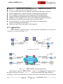
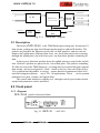
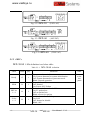
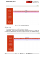
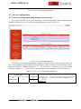
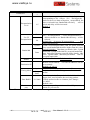
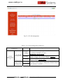
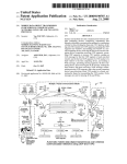
www.vaidsys.ru 1. General 1.1 Overview Thank you for selecting the MX-30/60 product designed and m ade by Changzhou Bell Data Com munication Equipm ents Co.,Ltd. The product can be used to provide E1 communication channels over Ethernet or IP networks. The MX-30/60 has m any optional para meters, which can be m odified by the user to suite dif ferent applicati on requirem ents. Please read this m anual carefully before installing the product. It is well known that the E1 signal comes from PCM technology which is TDM in nature. It transm its inform ation in a constant bit rate of E1_2048kbit/s, TDM technology occupies fixed transm ission bandwidth, with QoS features suitable for real-tim e applications such as voice and video. The QoS features include short and stable transmission delay, low jitter and wander, etc. On the other hand, Ethernet is based on statistical m ultiplexing, transmitting and exchanging inform ation in packets. It does not take up a fixed transm ission bandwidth, which is good for achieving higher bandwidth utilization. But Ethernet technology does not provide adequate QoS for real time applications. Until recently, voice and data were, and still are to a large extent, transported over two separate networks. But the require ment for both types of inform ation to be carried over a unified network is growing rapid. Packets over SONET/SDH techniques to integrate date into th e TDM network have been around for m any years. But for voice over packet based data networks, most of the efforts are spent on creating special equipm ent that packet s voice or video signals, such as VoIP techniques. However, to take advantage of the data network, it is neither cost ef fective, nor necessary to hastily replace all the TDM based equipm ent with new packet based equipm ent. The MX-30/60 can be used to em ulate transparent E1 channels over an Ethernet with adequate Qo S, so that most of the existing E1based applications can be readily setup over Et hernet LANs and W ANs. One particular suited application is to build E1 links with low cost wireless LAN bridges, replacing much more costly microwave radios. 1.2 Features User-friendly Web server supported for easy setup and maintenance Support SNMP V1 and V2 network management Point to point and point to multipoint supported Uplink ports 1+1 backup supported MX-30 an d MX-60 User Man ual V1 .2 -1- www.vaidsys.ru provide one E1 Port and MX-60 support two E1 ports Stable E1 clock recovery, low jitter and wander Low processing delay for E1 channels, high bandwidth usage efficiency Resist to packet loss, with PCM frame synchronization protection User definable encapsulation packet size for different application Support Ethernet encapsulation and UDP/IP protocol encapsulation Support VLAN settings for E1 service and in band VLAN management. Enough jitter buffer to resist packet delay variation (PDV) Local and remote E1 LOS and AIS and packet loss indication for trouble-shooting and maintenance Hardware and software program online upgrade MX-30 1.3 Applications MX-30/60 is used to setup 1~8 tran sparent E1 channels over LAN or IP networks, as depicted in Fig. 1.3-1. (a) Application in wireless (b) Point to Multipoint Application Fig. 1.3-1 MX-30/60 typical application MX-30/60 create 1~2 transparent E1 channels over In the figure, a pair of the packet network, providing connec tions between the PBX and telephone exchange, or other term inal devices. At the same time, computers talk to each other -2- MX-30 and MX-60 User Manual V1.2 www.vaidsys.ru through the local Ethernet ports on th e MX-30/60 s. This configuration guarantees that the E1 channels get higher priority over com puter data for maximum QoS. The m ost widely used application of MX-30/60 is to set up point to point wireless E1 links using low cost wireless LAN bridges. MX-30/60 can work with most LAN bridges on the m arket. It may be necessary to adjust different param eters such as packet size and packet jitter absorption buf fer size f or best operation f or different LAN bridges. WARNING: When connecting to a wireless LAN bridge, the uplink Ethernet cable often connects to the outdoor unit, posing danger to lightning strikes that can seriously damage the equipment. To protect the equipment as well as people, surge protection devices with good earth connection is strongly recommended. Poor earth connection may also hinder the operation of the Ethernet port, causing severe packet losses. 1.4 Timing modes To emulate a clear E1 channel over a packet network, the MX-30/60 not only conveys data stream content correctly from the source to the destination, but also passes tim ing. Packet networks do not provi de such built-in tim ing transparency mechanism as TDM networks do. MX-30/60 uses its proprietary algorithm to reconstruct the E1 clock at the destina tion. The recovered clock is of very high quality, with low jitter and wander. Typi cal frequency offset is within ±5ppm, and jitter is below 0.1UI. It can be adopted in most applications. This tim ing m ode of rebuilding the E1 clock at the destination is called Adaptive Timing. For applications where separate cloc k distribution network exists, another timing mode, Loop back Timing, may be used for maximum clock quality. The two timing modes of MX-30/60 are depicted in Fig.1.4-1. E1 IN E1 IN EthMux E1 port EthMux clock extract E1 port clock reconstruct E1 OUT Adaptive Timing buffer E1 OUT Loop back Timing Fig.1.4-1 E1Timing modes Correct timing mode setting is im portant for sm ooth operations. In m ost cases, setting both units to adaptive tim ing mode is suf ficient. But som etimes, setting one unit to loop tim ing mode may work better. For exam ple, setting the MX-30/60 unit connected with the clock m aster (suc h as local exchange) to loop back m ode, and the other unit connected with the clock slave (such as PBX or remote module) to MX-30 an d MX-60 User Man ual V1 .2 -3- www.vaidsys.ru adaptive mode, is probably better than setting both to adaptive modes. One typical error in telecom applications is to connect two com munication devices that are both clock slaves. Neither will MX-30/60 support such operation no mater how the timing modes are set. Note that E1 channel emulation takes several minutes to stabilize. During that period, clock drift may exceed the limit, errors and slips may occur. Various timing schemes are enlisted in Ta ble 1.4-1, for applications depicted in Fig.1.4-2. A side Equipment A E1 EthMux 10/100Base-Tx B side packet net 10/100Base-Tx EthMux E1 Equipment B Fig.1.4-2 Timing mode scheme reference diagram Table 1.4-1 Timing mode schemes Equipment A Equipment B clock mode clock mode master master master master master slave slave master A side B side MX-30/60 MX-30/60 Timing mode Timing mode loop back loop back adaptive adaptive adaptive adaptive loop back adaptive adaptive adaptive adaptive adaptive loop back adaptive Note Equipment A & B clocks synchronous Equipment A & B clocks plesiochronous slave slave Not allowed Note that setting both units to adaptive timing mode works well for all the conditions, although the other option may work better. 2. System architecture 2.1 Block diagram The internal functional structure of MX-30/60 is depicted below: -4- MX-30 and MX-60 User Manual V1.2 www.vaidsys.ru uplink port 1E1 or E1 lIU TDM/Packet processing 2E1 MII Ethernet switch local port local port power line power module +5V control unit Alarm Fig. 2.1-1 Functional diagram 2.2 Description The heart of MX-30/60 is the TDM/Packet processing unit. It truncates E1 data stream, putting the data into Ethernet packet with or without IP headers. The packets are passed to the Ethernet switch unit via MII interface, and are sent out adaptive the uplink ports. Ethernet data from two local data port are also sent out through the uplink ports, but with lower prio rity than those packets containing E1 data. In the reverse direction, packets from the uplink ports are sorted at the switch unit. All but E1 packets are passed to th e local data ports. The packets containing E1 data are sent to the TDM/Packet pr ocessing unit for reassem bling the original data stream, and recovering the E1 clock which is the key elem ent of the device. Very sophisticated algorithm is used to ensure that the reconstructed clock will meet the stringent requirem ent of TD M applications. The m ost im portant parameters are jitter, wander, and signal delay. The control unit interfaces with the user through console port so that various operational parameters can be modified. 2.3 Front panel 2.3.1 Diagram MX-30/60 panel is shown as below: Fig. 2.3.1 MX-30 MX-30 an d MX-60 (-48V DC) User Man ual V1 .2 -5- www.vaidsys.ru Fig. 2.3.2 MX-30 (220V AC) Fig. 2.3.3 MX-60 (-48V DC) Fig. 2.3.4 MX-60 (220V AC) 2.3.2 LED’s MX-30/60 LEDs definition is as below table: Table 2.3-1 Label Color Qty. Ready G 1 PWR R 1 PKT los 1~2 R 2 E1 los 1~2 R 2 -6- MX-30/60 definition Definition System work state indicator: On: System abnormal or system initialization. Off: System abnormal or system not work. Blink: Normal operation Power failure indicator Off: Normal On: Power Off / Failure Packet loss indicator for 1~2 E1: On: E1 packet loss Off: no packet loss Blink: not receive packet LOS indicator for 1~2 E1 ports On: LOS Off: Normal or disable Blink: AIS MX-30 and MX-60 User Manual V1.2 Note Located at the box panel www.vaidsys.ru 1~2 E1 addressing of rem ote equipm ent link state indication: REMOTE 1~2 Link/Act FDX G On: E1 obtain MAC address of remote equipment; 2 Off: E1 have not obtained MAC address of equipment; G 2 Y 2 remote Ethernet link activity indicator On: Link Blink: Data Off: Inactive duplex indicator On: Full duplex Off: Half duplex Blink: Conflict located at the Etherne t socket When power the device on, PW R indicator will be lit, indicator Ready will be on temporarily, which indicate the system is starting now. If the Ready light doesn’t blink as above, which indicate the process runs abnormally, please restart the system again. 2.4 Dip Switches Definition There are one 10-bit Dip Switch at the box bottom , the definition show as Table 2.4.1. ON 1 DIP 2 3 4 5 6 7 8 9 10 Fig 2.4-1 10-bit dip switch Dip ON OFF DIP-2 DIP-3 ON OFF OFF ON DIP-4~6 DIP-7~9 ON DIP-10 OFF DIP-1 Table 2.4-1 Dip Switches Definition label Definition CGND OPEN 120Ω 75Ω reserve reserve IP Deflt IP normal E1 75Ω output terminal outer shield grounded E1 75Ω output terminal outer shield open E1interface impedance set E1: 120Ω E1: 75Ω Reserved Reserved ON: Default IP address 192.192.192.192 OFF: User set IP address 2.5 Ethernet ports There are two RJ45 Ethernet ports on MX-30 an d MX-60 MX-30 panel, anyone could support User Man ual V1 .2 -7- www.vaidsys.ru uplink connection or access to NMS PC. Interface m ode support auto-negotiated, 100M full duplex, 100M half duplex, 10M full duplex and 10M half duplex. RJ45 Ethernet socket pins defined as: Table 2.5-1 RJ45 socket definition Pin 1 2 3 Definition TxD+ TxD- 4 5 RxD+ 6 7 8 RxD- Note: 10/100Base-Tx interface has HP auto-MDIX function and it can check the transmission and receiving sequence and make configuration. So both MDI and MDI-X interfaces are supported and both cross line and direct line can be selected. 2.6 E1 Port There are 1 or 2 E1 ports on the r ear panel of MX-30/60 adopt RJ45 connector. The E1 ports im pendence are E1-120 Ω, but could be convert to 75 Ω unbalanced by external im pedance m atcher. Default E1 ports are 120 Ω. RJ45 connector and wire sequence and signal defined as below: 1 8 Fig 2.6-1 RJ45 connector pin sequence Table 2.6-1 RJ45 120Ω-E1signal definition Pin Signal 1 - E1-IN 2 + 3 GND 4 5 + - E1-OUT 2.7 Power MX-30/60 support ~220V AC or -48V specified at the time of purchase. -8- MX-30 and MX-60 6 7 8 GND DC power supply. It should be User Manual V1.2 www.vaidsys.ru 3. Installation 3.1 Electrical 3.1.1 Power connection The MX-30/60 consumes less than 10W of power. According to power option, -48V DC or 220V (110V) AC, select the right power supply for the equipm ent. For the -48V type, connect -48 supply to the power connector -48V port, and ground to the other port. The screws on the power connector m ust be tightly fastened. For ~220V equipm ent, connect the device to the ~220V outlet with standard power cord supplied with the equipm ent. Note that there is a 1A fuse in the ~220V socket which may be replaced when burned. The -48V equipment uses PPTC resettable fuse, no customer replacement is required. It is recom mended to turn off the power switch before connecting or disconnecting the power. On the left corner of rear panel, a sc rew is used for connecting the chassis to the protective ground. Be sure to make this connection using a thick wire. WARNING: The system must be securely connected to a good protective ground for safety. All interconnected equipment must be grounded for maintaining signal integrity as well. Ground potential may also damage the interface ports. WARNING: To avoid electric shock, the ~220V outlet must have good ground. 3.1.2 E1 connections The E1 ports on MX-30/60 are used for connecting to E1 equipment such as the telephone exchange or PCM terminals. 1/2 E1 Ports Supported. E1 ports im pendence are E1-120 Ω f or twisted pair cables or 75Ω for coax. The E1-120Ω RJ45 sockets are default for ports. The E1-120Ω connection cable is m ade with RJ45 connectors and a length of 4-pair twisted cable. The cable is not provi ded with the equipm ent, and the user is responsible for m aking such cables in the fi eld with length suitable for a particular installation. The signal definition is given in Table 3.1-1, and pin order is depicted in Fig. 3.1-1. Note that pin-1 a nd pin-2 should use the sam e twisted pair, so should pin-4 and pin-5. MX-30 an d MX-60 User Man ual V1 .2 -9- www.vaidsys.ru 1 8 Fig. 3.1-1 RJ45 pin order Table 3.1-1 120 Ω-E1 signal definition Pin 1 2 3 4 5 6 7 8 + + Signal GND GND E1-OUT E1-IN The RJ45 sockets are default for E1-120Ω, when the 2nd and 3rd dip of 10-bit dip switch should be set to ON and OFF respectively; When the 2nd and 3rd dip of 10-bit dip switch are set to OFF and ON respectively, E1 interface impedance will be 75Ω.The cable BH4.851.122 is for one RJ45 connecter to two BNC (F) sockets conversion. Fig. 3.1-2 75Ω converting cable By NMS, E1ports provide local loop back and remote loop back, 1/2 E1 ports loop back can be set independently, and by the dip RA on front panel E1 indicators can be controlled to indicate local or rem ote ports LOS and AIS status. The local and remote loop back definition is shown as Fig 3.1-3: Fig 3.1-3 E1 loop back Rx Tx can test E1 connection cable, and Tx Rx is used to test the whole circuit including MX-30/60 in the two ends and the link between them. - 10 - MX-30 and MX-60 User Manual V1.2 www.vaidsys.ru 3.1.3 Ethernet connection Connect the uplink Ethernet port to the Et hernet transport network, such as the wireless LAN bridge, and connect the local data port to com puters or an Ethernet switch for local data applications. The signal definition of the two local Ethernet ports is given in Table 3.1.3-1. Table 3.1.3-1 Pin 1 Signal RxD+ 2 RxD- Ethernet signal definition 3 TxD+ 4 5 6 TxD- 7 8 Note: The ports confirm to HP auto-MDIX spec. It will automatically adapt to parallel or crossed cables. The signal definition of the uplink Ethernet ports is given in Table 3.1.3-2. Table 3.1.3-2 Ethernet signal definition Pin 1 2 3 Signal RxD+ RxD- TxD+ 4 GND 5 GND 6 TxD- 7 8 GND GND Note: The uplink port link parallel cable to LAN bridge. WARNING: When connecting to a wireless LAN bridge, the uplink Ethernet cable often connects to the outdoor unit, posing danger to lightning strikes that can seriously damage the equipment. To protect the equipment as well as people, surge protection devices with good earth connection is strongly recommended. Poor earth connection may also hinder the operation of the Ethernet port, causing severe packet losses. 4. Common faults This paragraph describes com mon m istakes and faults that m ay occur during installation and m aintenance. 4.1 E1 Alarms There are two groups of LEDs, PKT LOS and LOS for E1 alarms LEDs. When E1 LOS LED is on, loss of E1 Possible causes include: signal fault is detected by EthMux. The downstream equipment such as telephone exchange or PCM term inal is powered off. The E1 cable connection looses or broken. MX-30 an d MX-60 User Man ual V1 .2 -11- www.vaidsys.ru E1 LOS LED blinks when respective input E1 signal is AIS, i.e. the content of E1 data is all 1’s. Such alarm indicat es fault conditions on the part of the downstream equipment. E1 LOS site is controlled by Dip Switc h RA state. W hen RA Dip Switch ON, the red LEDs indicate remote E1 LOS state. When RA Dip Switch OFF, the red LEDs indicate local E1 LOS state. The E1 PKT LOS lights are packet loss indicator, On for Ethernet packet loss, Blink for E1 Packet Loss, Off for Normal. 4.2 Lnk/Act LED off Lnk/Act LED off means the corresponding Ethernet link is not working. Check the Ethernet cable connection, and the status of the device on the other end of the cable. 4.3 Ready LED does not blink After power on, the Ready LED should star t to blink. If not, try switch power off and on again. If this error persists, call for support. 4.4 Can not built communication Two ends of equipm ents are in one Et hernet broadcast dom ain, check the IP dual relations is right and MAC address should be unique. 4.5 Downstream reporting slips Check if the downstream equipm ent has correct clock m ode. At least one of them must be clock master. Set the EthMux on master side to loop back timing. If the downstream equipm ent on both side s is not synchronized, slips are not avoidable. At the transition time after power on or reapplying the E1signal, slips and errors are acceptable. Such transition may take several minutes. 5. Web Manager Both Web Server and SNMP management are supported through anyone of two Ethernet ports of MX-30/60 The management has four sections: Status, Line Test, Configuration and System. User nam e and password are required to enter the sections of Line Test Configuration and system . Both the defa ult user nam e and password are “root”. Customers can modify the user name and password in the System section. Note that the modifications of system will be valid after submit and reboot, - 12 - MX-30 and MX-60 User Manual V1.2 www.vaidsys.ru while the modifications of Line Test (E1 loop-back setting) and Configuration can be valid only after submit. Take MX-60 for exam ple, following sections will introduce W eb Server management detailedly. 5.1 Show current status menu After input the IP address, status in formation of MX-60 will be displayed such as hardware version, software version, IP address, subnet m ask, gateway address and MAC address. Details are shown in fig.5.1-1. Fig5.1-1 Status Menu Click on the line status option will bring the E1 line Status Inform ation window showing LOS, AIS, loop-back status and pow er fail. The alarm could be masked by related Alarm Mask settings, once alarm mask is set, alarm log, panel alarm indicators and alarm s in SNMP will all be masked, shown as Fig.5.1-2. MX-30 an d MX-60 User Man ual V1 .2 -13- www.vaidsys.ru Fig.5.1-2 E1 line Status Information 5.2 Line Test Loop back controls provide E1 line loop test function. Click on E1 Loop back option will bring the window as fig5.2-2. E1 setting can be valid after submit but not saved, that is, Eight E1s will not loop back after restart. - 14 - MX-30 and MX-60 User Manual V1.2 www.vaidsys.ru Fig.5.2-1 E1 Loop-back Management 5.3 Service Configuration 5.3.1 Service configuration and parameters instruction This section includes E1 service m anagement, VLAN management, Ethernet Management, SNMP configuration. Every section has many parameters setting. As Fig5.3-1. Fig.5.3-1 E1 service Management In the E1 service management menu, customers could set each E1 service num ber (Service No), service num ber support capital letter/sm all letter, digits and some special characters input, maximum 20 bits or 2 Chinese characters. N ote: Service N o. should not be some special characters such as “/”, “\” etc. E1 service managed parameters settings are described as below: Table 5.3-1 E1 service management parameters Selection s E1 Parameters E1 Managemen t E1 MX-30 T1 an d MX-60 Explanations For MX-60 service. Default: E1 E1 set is for both 2 channels of E1 User Man ual V1 .2 -15- www.vaidsys.ru Selection s Parameters Encapsulation Level 1~5 Yes Use IP Encapsulation No Uplink Bandwidth Data Enable E1 data size encapsulated in E1 , N = 1~5 optional, corresponding to 256 ×Nbyte(E1).The bigger the packet is the m ore data each packet encapsulated, the lower overhead it has. Bandwidth efficiency will be raised and delay will be increased. Default :2 Yes : IP encapsulation , source and destination IP address should be set. Bandwidth efficiency will be reduced (default)No : do not use IP encapsulation , high bandwidth efficiency Uplink: Set full duplex bandw idth for uplink Ethernet port,actual bandwidth should be higher than this value. Default 30000bps. Then data port bandw idth= U plink bandwidth=Uplink bandwidth-E1 occupied bandwidth. Data: limit local Ethernet ports full duplex bandw idth. Then Uplink bandw idth= data port bandw idth+E1 occupied bandwidth. Enable this E1 channel. Default: enable Remote end IP address ;4 E1 line IP addresses can be set separately Default 192.168.1.3 Destination IP Timing Mode Explanations Adaptive Loop back Adaptive mode:E1 timing from remote E1 stream; Loop back mode:E1 tim ing com es from local E1 stream Jitter absorption buffer: worked with the link with bigger jitter, used to buffer the receiving packets. Jitter Buffer 2~120ms Coming packets buffer to eliminate jitter. Range: 2~120ms。 Default 16ms From remote Select coresponding relation of local E1 ports to port remote E1 port service. Note: The sentence with underline is default settings. - 16 - MX-30 and MX-60 User Manual V1.2 www.vaidsys.ru Fig.5.3-2 VLAN management Table 5.3-2 VLAN management parameters Selection s Parameters VLAN Managemen t E1 VLAN Configuration Enable VLAN Priority Van ID Local Data VLAN Configuration MX-30 an d Data2 Data1/ monitor MX-60 Explanation Yes:with VLAN tag,support the VLAN network with priority to guarantee E1 QoS; (default)No:no VLAN tag Define users priority , including 8 levels (0-7), the number is bigger, the priority is higher. Default: 5 VLAN identify section, support 4096 VLAN identity . Range (0-4095). Default: 2662. Add vlan tag in local Ethernet service packet, the selection is as E1 VLAN Configuration default: disable vlan, priority 0, valn ID:1 User Man ual V1 .2 -17- www.vaidsys.ru Fig.5.3-3 Ethernet management Table 5.3-3 Ethernet management parameters Selection s Parameters Explanation 2 Ethernet ports status indication: Port: 2 Ethernet ports. Link: indicate current Ethernet link(Up/Down) Speed 10/100Mbps: indicate current Ethernet port speed Duplex: indicate current Ethernet work mode (half/full) 2 Ethernet ports work mode configuration: adaptive (default) 100Mfull 10Mfull 100M half 10M half Set Ethernet port alarm mask Port Eth Port Status Link Speed 10/100Mbps Duplex Mode Alarm mask 5.3.2 Service configuration indication 1. The MAC address of V-EMUX is fixed in the device. A RP is supported and the rem ote end MAC address can be got through auto-negotiation. So it is unnecessary to set the MAC address for the remote end, but IP address is needed. NOTE:Each device should have only one MAC address in the broadcast domain! 2. In order to im prove the E1 data transm ission service quality, according to Ethernet provided transmission support IEEE 802.1Q and 802.1por not, V-EMUX-8 can set whether to add VLAN tag with priority in the encapsulate process. According to 802.1Q/802.1p standard to packing, the encapsulation overhead is bigger (more 4 bits is added in each Ethernet packet), but - 18 - MX-30 and MX-60 User Manual V1.2 www.vaidsys.ru it also can be transm it according to priority le vel. But to the network which doesn’t support 802.1p, it is no sense to set VLAN but increase unnecessary bandwidth, so here should set VLAN to NO. 5.4 Network configuration The sy stem configuration includes network configuration, change passw ord, default parameters settings, save param eters and reboot the equipm ent. The interfaces are shown as below: 5.4.1 System network management Fig 5.4-1 network configuration system Table 5.4-1 system network management parameters Parameter Network Management Options Uplink1 Service No Uplink2 Service No IP Address Sub mark MX-30 an d MX-60 Description Set uplink port service number Set equipment IP address; default 192.168.1.2 It is used to judge the resource and destination IP is in one subnet or not, please and the resource and destination IP address by bit, they are in one subnet if the result is sam e, otherwise, they are in different subnet, should use gateway router; default 255.255.255.0. User Man ual V1 .2 -19- www.vaidsys.ru Gateway IP Address If resource and destination is not in one subnet, gatew ay IP address should be set, and gatew ay address should be in the sam e subnet w ith resource equipment. ARP is used to get address. Default 192.168.1.1 Same as E1 service N o in E1 service m anagement menu, Node ID, uplink Service N o. and Data service N o. also support capital letters/sm all letters, digits and som e special characters input, maximum 20 bits or 2 Chinese characters. N ote: Node ID and Service N o. should not be some special characters such as “/”, “\” etc. 5.4.2 Change the password Fig 5.4-2 change the password The change will be valid after confirm the submitting. - 20 - MX-30 and MX-60 User Manual V1.2 www.vaidsys.ru 5.4.3 Default parameter recovery Fig 5.4-3 default parameters menu 5.4.4 Save parameter Fig 5.4-4 Save parameter MX-30 an d MX-60 User Man ual V1 .2 -21- www.vaidsys.ru 5.4.5 Reboot system Fig5.4-5 Reboot equipment 6. Specification 6.1 Capacity It supports 1~2 E1 ports, two 10/100Base-Tx uplink Ethernet ports. 6.2 E1 interface Comply with ITU-T G.703 recommendation E1 port impedance E1-120Ω for twisted pair cables or 75 Ω for coax (The RJ45 E1-120Ω are default for ports) End-to-end delay (minimum delay setting) ≤ 10ms Output frequency offset (adaptive timing, stabilized) ≤5 ppm Output jitter (adaptive timing) ≤ 0.1UI 6.3 10/100Base-Tx port Comply with IEEE 802.3 10M/100M Adaptive Half/Full Duplex Adaptive Support 802.1Q MAC Uplink ports 1+1 backup supported Two user data ports supported. And Web manager supported through anyone of two user data ports. - 22 - MX-30 and MX-60 User Manual V1.2 www.vaidsys.ru 6.4 Power AC: 100V~260V/50Hz (fuse: 1A) DC: -38V ~ -62V (optional) Power Consumption: ≤4W 6.5 Operating condition Temperature: (0 ~45) ℃ Humidity: ≤90% (non-condensing) 6.6 Dimensions Width × Height × Depth: 185×35×138 mm 6.7 Weight ≤ 1 kg MX-30 an d MX-60 User Man ual V1 .2 -23-