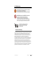
1
AMS-7000 Series Reverberation Chamber Wireless Measurement System User Manual ETS-Lindgren Inc. reserves the right to make changes to any products herein to improve functioning or design. Although the information in this document has been carefully reviewed and is believed to be reliable, ETS-Lindgren does not assume any liability arising out of the application or use of any product or circuit described herein; nor does it convey any license under its patent rights nor the rights of others. All trademarks are the property of their respective owners. © Copyright 2013–2015 by ETS-Lindgren Inc. All Rights Reserved. No part of this document may be copied by any means without written permission from ETS-Lindgren Inc. Trademarks used in this document: The ETS-Lindgren logo is a registered trademark, and EMCenter and EMQuest are trademarks of ETS-Lindgren Inc. Revision Record MANUAL,AMS-7000 SERIES | Part #399372, Rev. B ii Revision Description Date A Initial Release February, 2013 B Updated specifications and illustrations August, 2015 ets-lindgren.com Table of Contents Notes, Cautions, and Warnings ................................................ v 1.0 Introduction .......................................................................... 7 Standard Configuration ............................................................................... 8 ETS-Lindgren Product Information Bulletin ................................................. 9 2.0 Maintenance ....................................................................... 11 Performance Monitoring ............................................................................ 11 Owner/Operator Maintenance Items ......................................................... 12 Finger Stock Gasket ......................................................................... 12 Floor Connector Panels .................................................................... 12 Connectors ....................................................................................... 12 AMS-7000 Cleaning .......................................................................... 12 Tuner Assemblies ............................................................................. 13 Service Procedures .................................................................................. 14 Contacting ETS-Lindgren .................................................................. 14 Sending a Component for Service..................................................... 14 Calibration Services and Annual Calibration...................................... 14 3.0 Specifications ..................................................................... 15 Electrical Specifications ............................................................................ 15 RF Specifications ...................................................................................... 15 Physical Specifications ............................................................................. 16 4.0 Basic Theory of Operation ................................................ 17 5.0 Measured Performance ..................................................... 19 S21, S12, S11, and S22 Measurement ..................................................... 19 Shielding Effectiveness ............................................................................. 20 6.0 Measuring TRP/TIS for SISO Systems ............................. 23 Chamber Calibration ................................................................................. 24 Requirements for Chamber Calibration ............................................. 24 Hardware Configuration for Chamber Calibration .............................. 25 Procedure for Chamber Calibration ................................................... 26 Table: Absorber Loading for Different PDP Values, 1900 MHz .......... 30 TRP Measurement .................................................................................... 31 ets-lindgren.com iii Requirements for TRP Measurement ................................................ 31 Hardware Configuration for TRP Measurement ................................. 32 Procedure for TRP Measurement...................................................... 33 Table: Spectrum Analyzer Settings (If Used) ..................................... 34 TIS Measurement ..................................................................................... 35 Requirements for TIS Measurement ................................................. 35 Hardware Configuration for TIS Measurement .................................. 35 Procedure for TIS Measurement ....................................................... 36 7.0 Assembly ............................................................................ 37 Shipping Crate .......................................................................................... 37 Antennas .................................................................................................. 38 Typical Antenna Installation and Absorber Placement ....................... 38 AMS-7000 Illustrations .............................................................................. 40 AMS-7000 Front ............................................................................... 40 AMS-7000 Left Side .......................................................................... 41 AMS-7000 Right Side ....................................................................... 42 Appendix A: Warranty ............................................................. 43 Duration of Warranties .............................................................................. 43 iv ets-lindgren.com Notes, Cautions, and Warnings Note: Denotes helpful information intended to provide tips for better use of the product. Caution: Denotes a hazard. Failure to follow instructions could result in minor personal injury and/or property damage. Included text gives proper procedures. Warning: Denotes a hazard. Failure to follow instructions could result in SEVERE personal injury and/or property damage. Included text gives proper procedures. Note: See the ETS-Lindgren Product Information Bulletin for safety, regulatory, and other product marking information. ets-lindgren.com v This page intentionally left blank. vi ets-lindgren.com 1.0 Introduction The ETS-Lindgren AMS-7000 Series Reverberation Chamber Wireless Measurement System is designed to measure the over-the-air (OTA) performance of a wireless device. This can be used for measuring the Total Radiated Power (TRP) or Total Isotropic Sensitivity (TIS) of Single Input Single Output (SISO) devices. TRP is an emission-type measurement with the device acting as a radiating source and the average power level in the chamber measured over a predefined set of the boundary changes. TIS is a sensitivity measurement where an average power level in the chamber is established and the effectiveness of communication is tested as the power level in the chamber is reduced. The sensitivity limit is determined when some predefined error threshold is reached by the device. Reverberation chambers have been in use in the EMC community for several years with the main users being the military, automotive, and aircraft industries. The reverb chamber has always provided what has been considered a severe and realistic environment for immunity measurements because the test field is all-encompassing; it exists in the entire chamber volume and not just in the illumination direction, as is the case for anechoic chamber methods. Reverberation (reverb) chambers are fundamentally a resonant cavity in which a number of Eigen modes are supported related to the dimensions of the chamber. Each mode defines the spatial location of multiple maxima and minima in the chamber which, if dense enough when stirred, could provide an environment in which the E-field maxima is uniformly distributed. The modes that are supported in the chamber are a function of the frequency of the injected signal and the dimensions, and the Q of the chamber affects the magnitude of the resonance. This may be at a single CW frequency with a limited number of modes available in the chamber. When the bandwidth of the chamber is taken into account however, it becomes possible for a single CW frequency to excite a number of adjacent modes resulting in increased mode density. The distribution of the signal maxima in the chamber is fixed spatially if the cavity properties remain static. If the boundaries or frequency content are changed, then with the resulting movement of these maxima a statistically homogenous and isotropic environment can be realized. ets-lindgren.com Introduction 7 There are several methods that can be used to make the changes to the boundaries of the cavity and each method has merit based mainly on ease of automation, simplicity, and overall effectiveness for a particular measurement type. Most of the existing EMC test standards that describe a test method based on reverb chambers refer to the use of a mechanical reflecting structure that is either stirred continuously or stepped. The design of a reverb chamber depends on the application, and there can be differences in the implementation of many of the design components that result in one or another of a chamber’s attributes being optimized. Reverb chambers have become a very useful tool for immunity and shielding effectiveness measurements in the EMC community, and have been gaining increasing popularity for use in the wireless community in recent years. A suitably-sized reverb cavity can be used to perform TIS and TRP over-the-air measurements of wireless devices with a level of accuracy and repeatability that can be on a par with other established alternative anechoic methods. It can also be used to measure antenna efficiency as well as the throughput and diversity of MIMO devices, with test methodologies being developed to support these measurements. This document provides guidance on how to perform a calibration of the chamber and make TRP and TIS measurements for SISO technologies using the AMS-7000. Standard Configuration The AMS-7000 system consists of a reverberation chamber, a communication test set (Base Station Emulator), a Vector Network Analyzer (VNA), and an EMCenter™ switch matrix under the control of EMQuest™ EMQ-200 Reverb OTA Measurement Software. Other options are available to extend the operation of the system to support MIMO and Wi-Fi testing. 8 Introduction ets-lindgren.com ETS-Lindgren Product Information Bulletin See the ETS-Lindgren Product Information Bulletin included with your shipment for the following: Warranty information Safety, regulatory, and other product marking information Steps to receive your shipment Steps to return a component for service ETS-Lindgren calibration service ETS-Lindgren contact information ets-lindgren.com Introduction 9 This page intentionally left blank. 10 Introduction ets-lindgren.com 2.0 Maintenance CAUTION: Before performing any maintenance, follow the safety information in the ETS-Lindgren Product Information Bulletin included with your shipment. WARNING: Maintenance of the AMS-7000 is limited to the components as described in this manual; other maintenance is not required. Factory engineering personnel should be consulted in the event of damage or failure to operate properly after maintenance procedures. WARRANTY If you have any questions concerning maintenance, contact ETS-Lindgren Customer Service. Performance Monitoring On-site S Parameter measurements are normally performed at the conclusion of installation procedures for the AMS-7000 Series Reverberation Chamber Wireless Measurement System. They are also performed at the factory for all factory assembled chambers. If the chamber is to be installed by an ETS-Lindgren representative, then the on-site S Parameter measurement is the responsibility of the representative. Determination of continued performance to specified parameters may be ensured by periodic re-measurement of the S Parameter. This could detect changes in performance parameters that would signal unacceptable performance. The measurement should be performed on a schedule as determined by the customer’s Quality procedures. The default time period between such evaluations (this is not a calibration) is six months. ets-lindgren.com Maintenance 11 Owner/Operator Maintenance Items FINGER STOCK GASKET Some mesh gasket material and finger stock is used in the construction of the AMS-7000. The finger stock in the door is accessible in the normal course of chamber operation. Periodic visual inspections must be made to determine if there is need to clean the finger stock, or to replace it if damaged. Replacement finger stock for the doors is available from the factory; replacement finger stock for the connector panels (if used) is also available. Contact ETS-Lindgren for more information. To clean finger stock, use an aerosol lubricant to loosen the debris, and then low pressure air or another aerosol to remove the excess lubricant. Alternatively, a soft rag may be used to remove dirt and excess liquid from the finger stock. FLOOR CONNECTOR PANELS The turntable feed-through connector panel in the floor of the chamber will attract small particles of dirt or other debris. Periodic inspection is required to ensure continued satisfactory performance. To inspect for an accumulation of dirt, the turntable top should be removed and a vacuum used for cleaning. CONNECTORS The RF and other connectors are delicate in their wall-, turntable-, and floor-mounted positions. Periodic examination of these connectors for damage will prevent use of a damaged connector, ensuring proper operation of the system. Protect these connectors with caps when they are not in use. AMS-7000 CLEANING Overall cleaning of the AMS-7000 inner and outer surfaces may be performed by the use of standard non-abrasive, non-corrosive cleaners. Periodic cleaning of the interior with a vacuum cleaner will reduce the possibility of debris build up in the turntable area. 12 Maintenance ets-lindgren.com TUNER ASSEMBLIES The AMS-7000 uses two internally-mounted tuner assemblies driven from stepper motors mounted external to the chamber. The tuners are manufactured using a single lightweight aluminum rod to support the Z-fold section which provides the necessary reflective surface for effective mode stirring. No maintenance of the tuner structure is required in normal use but the surfaces can be dusted or vacuumed periodically to maintain their appearance. The tuners are supported at both ends by a coupling clamp at the motor end and a self-aligning bearing at the other end. Inspect these every month for signs of wear, loose screws, distortion, or noise. There is a grease nipple on the self-aligning bearing that is factory-lubricated and should remain maintenance-free in normal use. These should be checked periodically to ensure free smooth movement and that fixings remain secure, or if there is evidence of noise to see if additional lubrication is needed. Additional grease can be applied with a lever action grease gun. The motors mounted external to the chamber are fixed to the chamber wall and ceiling. Each motor shaft passes into the chamber via a shielded penetration fitted to the chamber. On all chambers the RF feedthrough assembly on the motor side of the tuner contains a large number of ball bearings. Do not remove these; they provide the RF shielding of the gear shaft as it passes through the shield. ets-lindgren.com Maintenance 13 Service Procedures CONTACTING ETS-LINDGREN Note: Please see www.ets-lindgren.com for a list of ETS-Lindgren offices, including phone and email contact information. SENDING A COMPONENT FOR SERVICE For the steps to return a system or system component to ETS-Lindgren for service, see the Product Information Bulletin included with your shipment. CALIBRATION SERVICES AND ANNUAL CALIBRATION See the Product Information Bulletin included with your shipment for information on ETS-Lindgren calibration services. 14 Maintenance ets-lindgren.com 3.0 Specifications Electrical Specifications Line Input: DUT Motor Drive (1) Tuner Motor Drive (2) 110/220 VAC 220 VAC 50/60 Hz 50/60 Hz Single Phase Single Phase 750 VA max. Fuse: 3A 250 V T 6A 250 VAC SISO TRP Test Type SISO TIS Test Type 700 MHz—6 GHz 700 MHz—6 GHz S21 ≤10.5 S21 ≤10.5 S11, S22 ≤1.75 S11, S22 ≤1.75 50 Ω 50 Ω N adapter (f) N adapter (f) E-field E-field RF Specifications Frequency Range: VSWR (Typical): Input Impedance: RF Connector Type: Shielding Effectiveness: ets-lindgren.com 100 dB minimum 100 dB minimum 700 MHz—18 GHz 700 MHz—18 GHz Specifications 15 Physical Specifications Note: See AMS-7000 Illustrations on page 40 for additional measurements. Height (outside): 2052 mm (80.81 in) Width (outside): 2081 mm (81.92 in) Depth (outside): 1394 mm (54.87 in) Weight: 500 kg (1100 lb) Door Dimensions: Width: 1.0 m (3.28 ft) Height: 1.5 m (4.92 ft) Nominal Test Volume in Center of Cell: Length: 0.9 m (35.4 in) Width: 0.9 m (35.4 in) Height: 0.6 m (23.6 in) Distributed DUT Load Rating: 16 Specifications 11.36 kg (25.0 lb) ets-lindgren.com 4.0 Basic Theory of Operation The AMS-7000 Series Reverberation Chamber Wireless Measurement System provides a resonant cavity fitted with two independently-controlled mechanical tuners and a turntable. The tuners are used to provide the boundary condition changes necessary to create variations of the spatial location of the E-field maxima in the chamber. The variation achieved with changes in the tuner position is limited by the number of modal variations available, especially at the low frequencies close to 700 MHz and within the number of independent samples that are achievable. With a significant number of boundary changes, it is possible to realize an area within the test volume where field uniformity can be demonstrated to be uniform within some standard deviation. In addition to the tuners, there is a turntable fitted in the floor of the chamber; it is used to support the Device Under Test (DUT) and one of the measurement antennas used only for calibration. Rotating the DUT and calibration antenna provides added samples of the measured distribution through spatial sampling, thereby reducing the uncertainty of measuring the maximum or the average of the E-field in the chamber. The location of the calibration antenna on the turntable close to the DUT ensures that similar statistics exist for this antenna during calibration and for the DUT during testing. For SISO testing there are three antennas installed in the chamber: A log spiral antenna is mounted directly above the test volume to provide direct illumination of the DUT. This antenna is used for communication with the DUT and is responsible only for maintaining the communication link during the rotation of the DUT. The location directly above the DUT ensures that there is a dominant signal component irrespective of the orientation of the DUT which is not significantly influenced by the reflected components in the chamber as the tuners and turntable are rotated. ets-lindgren.com Basic Theory of Operation 17 The main transmit/receive antenna is fixed to a rotating turret assembly on the chamber floor and directed upward at approximately 45 degrees. There is an added shielding panel positioned between the turret antenna and the turntable to minimize direct illumination of the test volume. This ensures that the RF energy that arrives at the test volume consists mainly of reflected components. This antenna is used as the source to generate the field conditions in the chamber for the TIS measurement and also as the receive antenna to measure the power level in the chamber during TRP measurements. The third antenna is a calibration antenna mounted on the turntable and directed away from the DUT position. This is used as a reference antenna for calibration of the chamber. Before any measurements can be made the characteristics of the chamber must be measured. This is done by measuring the transmission and reflection characteristics (S parameters) of the chamber relative to the antenna ports. This data is then used to form a correction factor versus frequency dataset that can be applied to the measurements made in the chamber. 18 Basic Theory of Operation ets-lindgren.com 5.0 Measured Performance The performance and operation of the reverberation chamber is based on the creation of a statistically-uniform environment within acceptable uncertainty. The uniformity of the test volume can be verified by direct measurement of the E-field using a three-axis field probe. For this measurement, the probe would be placed at different locations within the test volume in the chamber. At each probe location the tuners are stepped to different angular positions or stirred continuously and the field components measured to provide the required number of data samples. An alternative approach is to measure the variation in the transmission characteristics of the chamber by treating it as a two-port device. A Vector Network Analyzer (VNA) is connected to the two antenna feed ports on the chamber wall and turntable, and the maximum S11, S22, S12, and S21 are measured while the tuners and turntable are rotated. With this approach the calibration antenna can be moved to several discrete positions for each complete tuner rotation sequence and the variation in the S parameters compared for each location in the test volume. In both these methods, the boundaries of the chamber are changed through the rotation of the two tuners and the rotation of the receive (calibration) antenna or the E-field probe which is positioned on the rotating turntable. The second approach is much faster than the direct field method and can be used to provide additional information on the delay characteristics in addition to providing information on the ratio of the direct to indirect E-field components in the chamber. S21, S12, S11, and S22 Measurement The measured S parameters can be used to calculate a number of the chamber parameters. The coherence bandwidth of the system is found from multiple VNA measurements made over a complete stirring sequence. It is a function of the chamber configuration, including the DUT and antennas, as well as phantoms and test fixtures, if any are used. ets-lindgren.com Measured Performance 19 The easiest way to calculate the coherence bandwidth is to: 1. Determine the power delay profile (PDP) of the chamber. The PDP is the IFFT of the average of a series of S21 measurement. EMQuest™ Data Acquisition and Analysis Software provides time domain transform functionality under corrections for Reverb Chamber Vector Calibration Measurement. This measurement can be accessed in EMQuest EMQ-200 Reverb OTA Measurement Software; see the help file provided with EMQuest for more information. 2. Perform the chamber calibration following the procedure described and click to select the Calculate Power Delay Profile check box. This measurement should be done is 200 MHz-wide bands using at least 1000 samples 3. A simplified coherence bandwidth can be measured as the inverse of the rms delay spread. If the occupied bandwidth of the measured signal exceeds the coherence bandwidth, the reverberation chamber must be loaded with RF absorbing material. Loading the chamber is carried out iteratively until the coherence bandwidth exceeds the occupied bandwidth of the signal. Eight blocks of RF absorbers are provided to be used to vary the loading of the chamber to adjust the PDP or bandwidth requirements. Shielding Effectiveness The shielding effectiveness of the AMS-7000 Series Reverberation Chamber Wireless Measurement System is measured following the principles of the IEEE 299 method. A transmit source is placed outside each of the walls of the chamber and the level of the receive signal in the chamber is measured and compared to a reference measurement taken with the door open. Because of the chamber size, it is not practical to maintain the 1m separation of the measurement antennas and the 0.5m between the antenna and the chamber wall, so the method is modified slightly to take advantage of the inherent resonant properties of the reverb chamber. 20 Measured Performance ets-lindgren.com This modified method requires the maximum received level to be measured while the tuners in the chamber are rotated with the measurement receiver set to max hold. This reduces the risk of standing waves patterns in the chamber giving an erroneously optimistic shielding value. For the AMS-7000 the minimum level of SE is 100 dB in the frequency range of 700 MHz to 6 GHz. This has been verified with this method. ets-lindgren.com Measured Performance 21 This page intentionally left blank. 22 Measured Performance ets-lindgren.com 6.0 Measuring TRP/TIS for SISO Systems This section provides information on how to make Total Radiated Power (TRP) and Total Isotropic Sensitivity (TIS) measurements for Single Input Single Output (SISO) technologies using the AMS-7000 Series Reverberation Chamber Wireless Measurement System. Three sets of instructions are included: Chamber Calibration TRP Measurement TIS Measurement The AMS-7000 uses EMQuest™ EMQ-200 Reverb OTA Antenna Measurement Software. ets-lindgren.com Measuring TRP/TIS for SISO Systems 23 Chamber Calibration REQUIREMENTS FOR CHAMBER CALIBRATION 24 Vector Network Analyzer (VNA) Vector Network Analyzer Calibration Kit EMQuest EMQ-200 Reverb OTA Antenna Measurement Software Hardware Configuration for Chamber Calibration Measuring TRP/TIS for SISO Systems ets-lindgren.com HARDWARE CONFIGURATION FOR CHAMBER CALIBRATION ets-lindgren.com Measuring TRP/TIS for SISO Systems 25 PROCEDURE FOR CHAMBER CALIBRATION Note: As an alternative to the following procedure, the AUTO calibration routine can be used from EMQuest. Chamber calibration requires rotating the calibration antenna on the turntable for the different tuner positions. A minimum of 100 different sweeps or traces taken over the operating frequency range of 700 MHz to 6 GHz is required to obtain accurate calibration coefficients. Each sweep taken at a different position of the tuners and turntable represents a sample of the coupling between the two antennas at each frequency under different resonant conditions in the chamber. The average of this is used to produce the correction for the chamber. The following procedure can be used for basic chamber calibration: 1. 26 Perform a full two-port calibration of the VNA at the antenna ports using the calibration kit. Measuring TRP/TIS for SISO Systems ets-lindgren.com VNA Calibration at the Antenna Ports 2. Save the calibration on the VNA. 3. Connect Port1 on the VNA to Antenna1 (measurement antenna) and Port2 on the VNA to Antenna2 (reference antenna). 4. Select the Reverberation Chamber Vector Calibration Measurement test option in EMQuest to measure the chamber loss. Note: Steps 5 and 6 may change depending on the VNA used. 5. Place six blocks of absorber around the floor of the chamber for measurement from 700 MHz to 1 GHz and seven blocks for measurements above 1 GHz. 6. Set the calibration option in EMQuest for the VNA to Manual. ets-lindgren.com Measuring TRP/TIS for SISO Systems 27 7. Perform the requested manual calibration and then recall the saved calibration on the VNA. Run the measurement taking at least 100 sweeps (data points at each frequency) for different tuner positions (300 tuner positions recommended). If running continuous mode, select 3°/sec for the turntable and 1:8:8 turntable-to-tuner ratio 8. After the test is done, the saved raw data file will be used as a correction for TRP and TIS measurements in the respective frequency bands. 9. Set up a new Response Measurement parameter file in EMQuest for S21 measurement. 10. Measure the loss for the RF cable that will be used for TRP and TIS measurements. This cable will connect the measurement antenna to the spectrum analyzer during TRP, or RF in in the BSE, and the RF out on the communication tester to the measurement antenna during TIS. 11. Save the result in raw format; this file will be used as a correction factor in TRP and TIS measurements. 12. Since the calibration antenna is only used for the chamber calibration, the losses of the antenna can be removed from the correction data applied to the TRP and TIS measurement. This loss (≈0.34 dB) can be added as a constant correction in EMQuest. 28 Measuring TRP/TIS for SISO Systems ets-lindgren.com Sample S21 Data for a Loaded Chamber ets-lindgren.com Measuring TRP/TIS for SISO Systems 29 TABLE: ABSORBER LOADING FOR DIFFERENT PDP VALUES, 1900 MHZ 30 # Abs RMS Delay (ns) 0 434 1 257 2 178 3 142 4 119 5 100 6 90 7 81 8 74 9 69 10 64 Measuring TRP/TIS for SISO Systems ets-lindgren.com TRP Measurement REQUIREMENTS FOR TRP MEASUREMENT Communication Tester, Spectrum Analyzer (optional) EMQuest EMQ-200 Reverb OTA Antenna Measurement Software Correction files created and saved during the Chamber Calibration process EMQuest Control PC Communication Tester Spectrum Analyzer Loss corrected RF cable RF Cable GPIB Cable RS232 Cable ets-lindgren.com Measuring TRP/TIS for SISO Systems 31 HARDWARE CONFIGURATION FOR TRP MEASUREMENT 32 Measuring TRP/TIS for SISO Systems ets-lindgren.com PROCEDURE FOR TRP MEASUREMENT This measurement can be done in step mode or continuous rotation. In both cases the turntable will rotate the DUT to different positions as the two tuners are rotated. Place the Device Under Test (DUT) on the edge of the turntable in one of the slots provided. 1. Place the DUT as shown. DUT Placement under Communication Antenna on Smallest Side 2. Connect the output of the communication tester to the communication antenna in the chamber ceiling. Use the Reverberation Chamber Radiated Power Measurement test to perform the TRP measurement. 3. When setting up the parameter file, subtract both the Gref and Cable Loss correction files generated during the calibration process. 4. Set the number of samples to 100 in the test parameter file. ets-lindgren.com Measuring TRP/TIS for SISO Systems 33 5. Type 0.35 in the constant area at the lower right corner of the Corrections tab. This is a correction factor that reflects the reference antenna loss. 6. If a spectrum analyzer is being used—Spectrum analyzer settings are dependent on the technology standard. Use the following Spectrum Analyzer Settings table as a guideline. TABLE: SPECTRUM ANALYZER SETTINGS (IF USED) Parameter GSM/GPRS EGPRS (GMSK) (8-PSK) RWB 300 kHz 300 kHz 300 kHz VWB 300 kHz 300 kHz 300 kHz Sweep TDMA CDMA WCDMA (UMTS) 3 MHz 30 kHz 10 MHz 10 MHz (3 MHz if (3 MHz if 10 MHz 10 MHz not not supported) supported) 0.60 ms 0.60 ms 7 ms 100.00 ms ≥100 ms 501 501 501 501 501 RMS RMS RMS RMS RMS TDMA Pulse Average Integrated Time Points per Trace Detector Filter Trigger GSM GSM Pulse Pulse Video Video Video Free Run Free Run ≥Noise Floor ≥Noise Floor ≥Noise Floor NA NA +5 dB +5 dB +5 dB (-75 dB) (-75 dB) ≥Peak RX ≥Peak RX ≥Peak RX ≥Peak RX ≥Peak RX +5 dB +5 dB +5 dB +5 dB +5 dB (0 dBm) (0 dBm) (0 dBm) (0 dBm) (0 dBm) Mode Trigger Level Reference Level 34 Measuring TRP/TIS for SISO Systems ets-lindgren.com Parameter Flatness GSM/GPRS EGPRS (GMSK) (8-PSK) TDMA CDMA WCDMA NA NA NA 20 dB 20 dB 1 10–20 1 1 1 (UMTS) Tolerance Filter Average TIS Measurement REQUIREMENTS FOR TIS MEASUREMENT Communication Tester EMQuest EMQ-200 Reverb OTA Antenna Measurement Software Correction files saved during the Chamber Calibration process HARDWARE CONFIGURATION FOR TIS MEASUREMENT ets-lindgren.com Measuring TRP/TIS for SISO Systems 35 PROCEDURE FOR TIS MEASUREMENT This procedure is very similar to TRP, except that the downlink is through the measurement antenna. 1. Place the DUT as shown. DUT Placement under Communication Antenna on Smallest Side 36 2. Use the Reverberation Chamber Sensitivity Measurement test to perform the TIS measurement. 3. When setting up the parameter file, subtract both correction files generated during the calibration process. 4. Type 0.35 dB in the constant area at the lower right corner of the Corrections tab. This is a correction factor that reflects the loss of the reference antenna. (Same as for TRP.) Measuring TRP/TIS for SISO Systems ets-lindgren.com 7.0 Assembly CAUTION: Before connecting any components, follow the safety information in the ETS-Lindgren Product Information Bulletin included with your shipment. The AMS-7000 Series Reverberation Chamber Wireless Measurement System is manufactured using the pan-formed panel technology that ETS-Lindgren has used in full-sized chambers for several decades. The 2-mm thick aluminum panel sections that form the chamber are bolted together with a double row knit mesh gasket to provide better than 100 dB of shielding effectiveness across the 700 MHz to 6 GHz operating frequency range. There is a single large 1.0m x 1.5m knife edge swing door based on the RFD-100 door design, with an ergonomic vertical latching bar with free-wheeling handle. This provides easy access to the test area within the chamber. There are two Z-fold tuners fitted in the chamber, one mounted vertically in the right corner and the other mounted horizontally along the left wall. A turntable is located in the floor with the top of the turntable maintaining a flush internal floor surface. The chamber is built on an integral support frame with locking castors which provide for easy movement throughout the test lab. Shipping Crate Note: Contact ETS-Lindgren for shipping crate dimensions. The AMS-7000 is calibrated at the factory and shipped as a fully assembled unit in a single shipping crate. The crate includes a removable side panel and ramp to provide easy removal of the AMS-7000 without the need for special lifting equipment. ets-lindgren.com Assembly 37 Antennas The measurement antennas are removed for shipment to prevent damage during transit, and will need to be reinstalled. There are four antennas to be installed: (3) Model 3115 Double-Ridged Waveguide Horns (1) Model 3102 Conical Log Spiral The log spiral is installed in the ceiling of the chamber supported by an N f-f adapter, and the two SISO horn antennas are mounted in the side walls and on the turntable. Following are photos of typical antenna installation and absorber placement. TYPICAL ANTENNA INSTALLATION AND ABSORBER PLACEMENT Model 3115 Double Ridged Waveguide Horn 38 Assembly ets-lindgren.com Model 3115 Double Ridged Waveguide Horns Model 3102 Conical Log Spiral ets-lindgren.com Assembly 39 AMS-7000 Illustrations AMS-7000 FRONT 40 Assembly ets-lindgren.com AMS-7000 LEFT SIDE ets-lindgren.com Assembly 41 AMS-7000 RIGHT SIDE 42 Assembly ets-lindgren.com Appendix A: Warranty Note: See the Product Information Bulletin included with your shipment for the complete ETS-Lindgren warranty for your AMS-7000. Duration of Warranties All product warranties, except the warranty of title, and all remedies for warranty failures are limited to the durations outlined below for each product. Product Warranted Duration of Warranty Period AMS-7000 Performance 5 Years Filters 1 Year Doors & Accessories 1 Year Positioning Equipment 2 Years Antennas 2 Years ets-lindgren.com Warranty 43