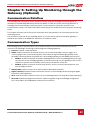
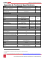
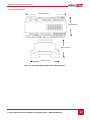
1
Disclaimers Disclaimers Important Notice Copyright © SolarEdge Inc. All rights reserved. No part of this document may be reproduced, stored in a retrieval system or transmitted, in any form or by any means, electronic, mechanical, photographic, magnetic or otherwise, without the prior written permission of SolarEdge Inc. This document is solely for the use of SolarEdge customers and employees. The material furnished in this document is believed to be accurate and reliable. However, SolarEdge assumes no responsibility for the use of this material. SolarEdge reserves the right to make changes to the material at any time and without notice. You may refer to the SolarEdge web site (www.solaredge.com) for the most updated version. All company and brand products and service names are trademarks or registered trademarks of their respective holders. Patent marking notice: http://www.solaredge.com/groups/patent Exclusion of Liability The general terms and conditions of delivery of SolarEdge shall apply. The content of these documents is continually reviewed and amended, where necessary. However, discrepancies cannot be excluded. No guarantee is made for the completeness of these documents. FCC Compliance This equipment has been tested and found to comply with the limits for a Class B digital device, pursuant to part 15 of the FCC Rules. These limits are designed to provide reasonable protection against harmful interference in a residential installation. This equipment generates, uses and can radiate radio frequency energy and, if not installed and used in accordance with the instructions, may cause harmful interference to radio communications. However, there is no guarantee that interference will not occur in a particular installation. If this equipment does cause harmful interference to radio or television reception, which can be determined by turning the equipment OFF and ON, you are encouraged to try to correct the interference by one or more of the following measures: Reorient or relocate the receiving antenna. Increase the separation between the equipment and the receiver. Connect the equipment into an outlet on a circuit different from that to which the receiver is connected. Consult the dealer or an experienced radio/TV technician for help. Changes or modifications not expressly approved by the party responsible for compliance may void the user’s authority to operate the equipment. Control and Communication Gateway Installation Guide - MAN-01-00132-1.2 1 Table of Contents Table of Contents Disclaimers ......................................................................................................................... 1 Important Notice ...............................................................................................................1 Exclusion of Liability ...........................................................................................................1 FCC Compliance .................................................................................................................1 Table of Contents ............................................................................................................... 2 About This Guide ................................................................................................................ 4 Support and Contact Information ....................................................................................... 5 Handling and Safety Instructions ........................................................................................ 6 Chapter 1: Introducing the SolarEdge Control and Communication Gateway ...................... 7 Overview ............................................................................................................................7 Control and Communication Gateway Interfaces ..............................................................8 LCD and LCD-Menu Buttons...............................................................................................9 LEDs ...................................................................................................................................9 Communication Connectors ..............................................................................................9 Other Interfaces ...............................................................................................................10 Chapter 2: Installing the SolarEdge Gateway .................................................................... 11 Safety ...............................................................................................................................11 Transport and Storage .....................................................................................................11 Package Contents ............................................................................................................11 Installation Equipment.....................................................................................................11 Installation Guidelines .....................................................................................................12 Installation Workflow ......................................................................................................12 Mounting and Connecting the SolarEdge Gateway .........................................................13 Connecting the SolarEdge Gateway to AC .......................................................................14 Chapter 3: Connecting the SolarEdge Gateway to the SolarEdge Installation .................... 15 Overview ..........................................................................................................................15 Connecting and Configuring the RS485 ...........................................................................15 Verifying the Connection .................................................................................................19 Troubleshooting the RS485 Communication ...................................................................19 RS485 Configuration Options ...........................................................................................20 Chapter 4: Connecting Environmental Sensors (Optional) ................................................. 22 Overview ..........................................................................................................................22 Connecting Sensors to the SolarEdge Gateway ...............................................................23 Configuring Environmental Sensors .................................................................................25 Menus ..................................................................................................................................... 25 Configuring the Sensors in the SolarEdge Gateway ................................................................. 26 Example of Sensor Graph Configuration ..........................................................................28 Sensor Connection Example ............................................................................................29 2 Control and Communication Gateway Installation Guide - MAN-01-00132-1.2 Table of Contents Chapter 5: LCD – Status Screens and Setup Options .......................................................... 32 Status Screens ..................................................................................................................32 Initial Gateway Status.............................................................................................................. 32 ID Status .................................................................................................................................. 32 Server Communication Status ................................................................................................. 32 IP Status .................................................................................................................................. 33 ZigBee Status ........................................................................................................................... 33 Wi-Fi Status ............................................................................................................................. 33 Communication Ports Status ................................................................................................... 34 Sensors Status ......................................................................................................................... 34 Setup Menu Options ........................................................................................................35 Language ................................................................................................................................. 37 Communication ....................................................................................................................... 37 Power Control ......................................................................................................................... 39 Sensors .................................................................................................................................... 39 Display ..................................................................................................................................... 39 Maintenance ........................................................................................................................... 39 Information ............................................................................................................................. 40 Chapter 6: Setting Up Monitoring through the Gateway (Optional) .................................. 41 Communication Dataflow ................................................................................................41 Communication Types .....................................................................................................41 Creating an Ethernet (LAN) Connection...........................................................................42 Overview ................................................................................................................................. 42 Ethernet Communication Configuration Options .................................................................... 42 Connecting and Configuring LAN ............................................................................................. 43 Troubleshooting Ethernet Communication ............................................................................. 44 Additional Connection Options ........................................................................................45 Wireless ZigBee Connection .................................................................................................... 45 Wi-Fi Connection ..................................................................................................................... 45 Appendix A: Technical Specifications ................................................................................ 46 Control and Communication Gateway Installation Guide - MAN-01-00132-1.2 3 About This Guide About This Guide This user guide is intended for Photovoltaic (PV) system owners, installers, technicians, maintainers and integrators who use the SolarEdge power harvesting system. This guide describes the process of installing and configuring the SolarEdge Control and Communication gateway (also referred to as SolarEdge gateway). This guide assumes that the SolarEdge power harvesting system is already installed and commissioned. For additional information about how to install and commission the SolarEdge power harvesting system, refer to the relevant inverter or safety and monitoring system (SMI) installation guide. The guide includes the following chapters: Chapter 1: Introducing the SolarEdge Control and Communication GatewayChapter 1: Introducing the SolarEdge Control and Communication Gateway, page 7, introduces the SolarEdge control and communication gateway. Chapter 2: Installing the SolarEdge Gateway, page 11, describes how to install the SolarEdge gateway. Chapter 3: Connecting the SolarEdge Gateway to the SolarEdge Installation, page 15, describes how to connect the control and communication gateway to inverters or Safety and Monitoring Interface (SMI) using the RS485 bus connection. Chapter 4: Connecting Environmental Sensors (Optional), page 22, describes how to connect and configure external environmental sensors to the SolarEdge gateway. Chapter 5: LCD – Status Screens and Setup Options page 29, describes how to configure the SolarEdge gateway and how to identify its status. Chapter 6: Setting Up Monitoring through the Gateway, page 41, describes how to set up communication through the SolarEdge gateway to the SolarEdge monitoring portal. Appendix A: Technical Specifications, page 46, provides the electrical and mechanical specifications of the SolarEdge gateway device. For further information, datasheets and the most up-to-date certifications for various products in different countries, please visit the SolarEdge website: www.solaredge.com 4 Control and Communication Gateway Installation Guide - MAN-01-00132-1.2 Support and Contact Information Support and Contact Information If you have technical queries concerning our products, please contact us: Australia 1800 465 567 [email protected] Belgium 0800 73041 [email protected] France 0800 917410 [email protected] Germany +49 89-45459730 [email protected] Italy 800 784 824 [email protected] Japan +81.3.5530.9360 [email protected] APAC (Asia Pacific) [email protected] United Kingdom 0800 028 1183 [email protected] US & Canada 1 877 360 5292 [email protected] Greece 0080 0125574 Israel +972 73 240-3118 Netherlands 0800 0221089 Worldwide +972 73 240-3118 Fax +972 73 240-3117 [email protected] Before contacting, ensure you have the following information at hand: The communication method to the SolarEdge server The product serial number as appears on its label. The serial number can also be viewed in the ID Status screen, as described on page 32. The software version, which can be viewed in the ID Status screen, as described on page 32 Control and Communication Gateway Installation Guide - MAN-01-00132-1.2 5 Handling and Safety Instructions Handling and Safety Instructions During installation, testing and inspection, adherence to the following handling and safety instructions is mandatory. The following safety symbols may be used in this document. Familiarize yourself with the symbols and their meaning before installing or operating the system. WARNING! Denotes a hazard. It calls attention to a procedure that, if not correctly performed or adhered to, could result in injury or loss of life. Do not proceed beyond a warning note until the indicated conditions are fully understood and met. CAUTION: Denotes a hazard. It calls attention to a procedure that, if not correctly performed or adhered to, could result in damage or destruction of the instrument. Do not proceed beyond a caution sign until the indicated conditions are fully understood and met. NOTE: Denotes additional information about the current subject. IMPORTANT SAFETY FEATURE: Denotes information about safety issues. 6 Control and Communication Gateway Installation Guide - MAN-01-00132-1.2 Chapter 1: Introducing the SolarEdge Control and Communication Gateway Chapter 1: Introducing the SolarEdge Control and Communication Gateway Overview The SolarEdge control and communication gateway expands the SolarEdge monitoring and control capabilities. It can be connected to SolarEdge and non-SolarEdge inverters, environmental sensors and revenue meters and can transfer the monitoring data to the SolarEdge monitoring server and optionally, to a non-SolarEdge logger. The control and communication gateway can connect to the following devices1: SolarEdge devices, such as inverters and safety and monitoring interfaces (SMIs) Non-SolarEdge inverters for inverter data monitoring on the SolarEdge portal Environmental sensors Revenue grade meters 3rd party external loggers for inverter data monitoring Power reduction control devices NOTE: Sensors, meters, loggers, and power reduction control devices are sold separately . Figure 1: The SolarEdge Control and Communication Gateway 1 For a list of supported environmental sensors, revenue meters, and third party inverters, refer to http://www.solaredge.com/articles/se-supported-devices Control and Communication Gateway Installation Guide - MAN-01-00132-1.2 7 Chapter 1: Introducing the SolarEdge Control and Communication Gateway Figure 2: Example of sensor connection to the SolarEdge gateway Control and Communication Gateway Interfaces Optional Optional Antenna1 Antenna2 (ZigBee) Control RS485-1 SW1 RS485-2 RS232 USB SW2 LCD LEDs: DC Micro SD Ethernet Green (power Yellow supply Red input) Enter (3) Down (2) Up (1) Esc Sensors LCD Buttons Figure 3: Control and Communication Gateway Interfaces 8 Control and Communication Gateway Installation Guide - MAN-01-00132-1.2 Chapter 1: Introducing the SolarEdge Control and Communication Gateway LCD and LCD-Menu Buttons The LCD screen displays status information of the SolarEdge gateway and various menus for configuration options. The LCD panel and buttons are used during the following processes: Operational Mode: The LCD panel allows checking that the gateway is working properly. Refer to Status Screens on page 32 for a description of this option. Use the LCD user buttons to toggle through the informative displays and select options. Setup: After mounting the gateway, the installer may perform basic gateway configuration, as described in Setup Menu Options on page 35. Four buttons are used for controlling the LCD menus (see Figure 3): Esc: Moves the cursor to the beginning of the parameter, goes to the previous menu and cancels a value change. Up (1), Down (2): Moves the cursor between menu options, moves among the characters of a parameter, and toggles between possible characters when setting a value. Enter (3): Selects a menu option or accepts a value change. Also used to enable LCD backlight. LEDs The front of the SolarEdge gateway has an LCD panel and three LEDs, as shown above: The gateway has three LED indicators, as follows: Power OK (Green): Indicates whether or not the SolarEdge gateway is connected to power Communication (Yellow): This LED blinks when monitoring information is received from another SolarEdge device in the installation. Fault (Red): Indicates that there is an error. For more information, contact SolarEdge support. All LEDs are ON while the SolarEdge gateway is being configured and during power up. Communication Connectors Antenna1: used for optional wireless ZigBee or Wi-Fi antenna connection (refer to Wireless ZigBee Connection and Wi-Fi Connection on page 45. Antenna2: Currently not installed RS485-1 and RS485-2: used for connecting external devices to the gateway (refer to Chapter 3: Connecting the SolarEdge Gateway to the SolarEdge Installation on page 15) RS232: enables connection of the SolarEdge gateway to an external device using an RS232 interface. USB: Enables PC/laptop connection for using the SolarEdge configuration tool. Ethernet: enables connecting the SolarEdge gateway to the SolarEdge monitoring portal through an Ethernet switch/router (refer to Creating an Ethernet (LAN) Connection on page 42). The Ethernet switch/router should be connected to the Internet. Control and Communication Gateway Installation Guide - MAN-01-00132-1.2 9 Chapter 1: Introducing the SolarEdge Control and Communication Gateway Other Interfaces DC: used for the power supply input as described in Connecting the SolarEdge Gateway to AC on page 14. Sensors: enables connecting to external environmental sensors (refer to Chapter 4: Connecting Environmental Sensors (Optional) on page 22). Control: used for connection to an external power reducer device SW1/SW2: RS485-1/2 termination Micro SD: used for field software upgrade 10 Control and Communication Gateway Installation Guide - MAN-01-00132-1.2 Chapter 2: Installing the SolarEdge Gateway Chapter 2: Installing the SolarEdge Gateway Safety CAUTION: For North America only: The product’s communication with external devices, must not use wires that span more than one building, as per the UL 60950-2 standard. Transport and Storage Transport the SolarEdge gateway in its original packaging, without exposing it to unnecessary shocks. If the original package is no longer available, use a similar box, which can be closed fully. Store the SolarEdge gateway in a dry place where ambient temperatures are -40°C (-40°F) to +60°C (140°F). Package Contents Control and communication gateway 100-240VAC to 12VDC (50 Hz/60 Hz) power supply with an interchangeable AC plug (US,EU,AU) Accessory kit including: Three 3-pin terminal blocks One 7-pin terminal block One 6-pin terminal block Installation Equipment Standard tools can be used during the installation of the SolarEdge gateway. The following is a recommendation of the equipment needed for installation: DIN rails Drill and 4mm diameter bits Three twisted wires or four-wire twisted pair cable For installing the communication options: CAT5/6 Ethernet cable Control and Communication Gateway Installation Guide - MAN-01-00132-1.2 11 Chapter 2: Installing the SolarEdge Gateway Installation Guidelines The following requirements apply when locating and mounting the SolarEdge gateway: The SolarEdge gateway is suitable for mounting indoors only. For outdoor installation, use an external outdoor enclosure (not provided by SolarEdge) The SolarEdge gateway must always remain in an ambient temperature of -20°C (-4°F) to +60°C (140°F). Cable specifications: Connection Type Cable Type Maximum Length RS485 communication bus (per RS485 port) Three twisted wires or 4-wire twisted pair cable (two twisted pairs). Recommended wire size: 20 AWG / 0.52 mm2 1,000m (3,330 ft) Ethernet CAT5/6 100m (325 ft). Sensor/control interface Recommended wire size: 20 AWG / 0.52 mm2 50m (165 ft) The SolarEdge gateway power supply requires a socket outlet with a grid voltage of 100 V - 240 V. Protect the SolarEdge gateway from dust, wet conditions, corrosive substances and vapors. Installation Workflow The following provides an overview of the workflow for installing and setting up the control and communication gateway Step 1 Step 2 Mounting the control and communication gateway Connecting the control and communication gateway to the SolarEdge installation Step 3 Page 13 Page 15 Page 22 Connecting envirinmental sensors (optional) Step 4 Page 35 Configuring the control and communication gateway and inverters/SMI Step 5 12 Using the control and communication gateway to connect the installation to the monitoring server (optional) Page 41 Control and Communication Gateway Installation Guide - MAN-01-00132-1.2 Chapter 2: Installing the SolarEdge Gateway Mounting and Connecting the SolarEdge Gateway The SolarEdge gateway can be installed on a wall or on a DIN rail. ► To mount the SolarEdge gateway on a wall: 1 Determine the mounting location. Leave clearance from all sides of the SolarEdge gateway for cover opening, cable connection and routing. 2 Open the clips at the rear of the gateway by pushing the clips outwards. Wall mount holes Press here Press here Figure 4: Clips in Open position 3 Position the device on the wall with the open clips, as shown in Figure 4. Mark points through the holes of the clips and drill holes using a 4mm diameter drill bit. 4 Mount the unit using screw anchors and screws (use 3.5mm diameter screws, 20mm minimum length, not provided by SolarEdge). ► To mount the SolarEdge gateway on a DIN rail: 1 Ensure that the clips are closed, as shown below: Press here Press here Figure 5: Clips in Closed position Control and Communication Gateway Installation Guide - MAN-01-00132-1.2 13 Chapter 2: Installing the SolarEdge Gateway 2 Hook the two lower clips of the SolarEdge gateway onto the lower edge of the DIN rail. 3 Press the SolarEdge gateway upwards and snap it into the upper edge of the DIN rail. When on the rail, the clip "grips" the rail on both the top and bottom lips of the rail. To remove the DIN clip from the rail, simply push upwards on the DIN clip (thereby compressing the springs in the bottom), pivot the top of the clip off of the rail, and then move the whole clip down to also release the bottom of the clip. No screwdrivers or special tools are required. 4 The following figure shows the gateway’s rear side when mounted on a DIN rail. DIN rail clips Figure 6: Gateway mounted on a DIN rail Connecting the SolarEdge Gateway to AC For connecting to power, use the supplied power supply: 1 Insert the power supply DC connector to the SolarEdge gateway (see Figure 3). 2 Connect the power supply to the AC mains. The LEDs are lit momentarily to indicate power connection (see Figure 3). CAUTION: If you use a non-SolarEdge power supply, check that it has 12Vdc/1A output ratings, and that it is certified to UL/CSA/IEC60950-1 2ed standards. Limited Power Source output, NEC class 2. Verify the power supply polarity as marked on the gateway. 14 Control and Communication Gateway Installation Guide - MAN-01-00132-1.2 Chapter 3: Connecting the SolarEdge Gateway to the SolarEdge Installation Chapter 3: Connecting the SolarEdge Gateway to the SolarEdge Installation Overview The SolarEdge control and communication gateway connects to the PV system installation using the RS485 communication option. The RS485 option enables creating a chain (bus) of up to 31 slave SolarEdge devices, connected to one master, which can be another SolarEdge device or the SolarEdge control and communication gateway. The following is an example of a master gateway connected to a chain of slave inverters. Terminated (Terminated) Figure 5: Example of RS485 connection The following sections describe how to connect the RS485 bus and how to configure its components. Connecting and Configuring the RS485 The RS485 bus uses a three-wire cable connecting the RS485-1/2 terminal blocks on the SolarEdge gateway to the RS485 input of the inverters/SMI. ► To connect the RS485 communication bus between inverters/SMIs and SolarEdge gateway: 1 Use one of the supplied 3-pin terminal blocks: Loosen the screws and insert the wire ends into the A, B and G pins. For connections longer then 10m use twisted pair wires for A and B wires. G B A Figure 7: 3-pin terminal block Control and Communication Gateway Installation Guide - MAN-01-00132-1.2 15 Chapter 3: Connecting the SolarEdge Gateway to the SolarEdge Installation 2 Choose either RS485-1 or RS485-2 for connection. Connect the 3-pin terminal block to the designated port on the gateway. NOTE: RS485-1 is configured as SolarEdge device by default, therefore RS485-1 is recommended as the RS485 bus connection point. 3 If the gateway is at the end of the RS485 chain, terminate the gateway by switching a termination dipswitch to ON. The switches in the SolarEdge gateway are marked SW1 for the RS485-1 port termination and SW2 for the RS485-2 port termination, as shown below: On Off A B G SW1 SW2 RS485- 2 A B G RS485-1 Figure 8: RS485 connectors and termination switches 4 Open the inverter/SMI cover as described in their manual. 5 Remove the seal from one of the openings in communication gland #2 of the inverter and insert the cable through the opening. 6 Pull out the 9-pin RS485/RS232 terminal block connector, as shown below: Figure 9: The RS485/RS232 terminal block in the inverter/SMI 16 Control and Communication Gateway Installation Guide - MAN-01-00132-1.2 Chapter 3: Connecting the SolarEdge Gateway to the SolarEdge Installation 7 Loosen the screws of pins B, A and G on the left of the RS-485 terminal block: For inverter: RS485-1 pins (left-most) For SMI: RS485-1 (recommended, as this is the default configuration), or RS485-2 Screws G A RS485-2 (used in SMI only) B G A RS485-1 B Figure 10: RS485/RS232 8 Insert the ends of wires into the G, A and B pins shown above. You can use any color wire for each of the A, B and G connections, as long as the same color wire is used for all A pins, the same color for all B pins and the same color for all G pins. 9 Connect all B, A and G pins in all inverters/SMI. The following figure illustrates this connection schema (the illustration applies to both inverters and SMI): SolarEdge Gateway Figure 11: Connecting SolarEdge devices (inverters or SMI) in a chain NOTE: Do not cross-connect B, A and G wires. For inverters - Do not insert wires into RS485-2 pins. Control and Communication Gateway Installation Guide - MAN-01-00132-1.2 17 Chapter 3: Connecting the SolarEdge Gateway to the SolarEdge Installation 10 Tighten the terminal block screws. 11 Push the RS485 terminal block firmly all the way into the communication board. 12 Terminate the inverters/SMIs at the two ends of the chain by switching a termination dipswitch inside the inverter/SMI to ON (move the switch to the top). The switch is located on the communication board and is marked SW7. Use the left switch Figure 12: RS485 termination switch NOTE: Only the first and last SolarEdge devices in the chain should be terminated. The other devices in the chain should have the termination switch OFF. ► To configure the RS485 communication bus with SolarEdge inverters/SMI: By default, all SolarEdge devices are pre-configured as slaves. Slaves can be further configured using the RS485-x Conf option in the Communication menu. One device must be set as the master on the RS485 bus. Any one of the SolarEdge devices may be the master (control and communication gateway, inverter, or SMI). If you connect the installation to the SolarEdge monitoring portal, the device used to connect to the server must be the master. The following describes how to configure the master device. 1 Press the Enter button until the following message is displayed: P l e a s e e n t e r P a s s w o r d * * * * * * * * The gateway is now in Setup mode and all its LEDs are lit. 2 Use the three-right-most LCD buttons to type in the following password: 12312312. The following menu is displayed: L C S D M I 18 a o e i a n n m n s i f g m s p n o u u o l t r a n r a e m g i s y n a e < e n g > c a t i o n a n c e t i o n Control and Communication Gateway Installation Guide - MAN-01-00132-1.2 Chapter 3: Connecting the SolarEdge Gateway to the SolarEdge Installation 3 Short-press the arrow buttons to scroll to the Communication menu. Press the Enter key to select it. 4 Select Server RS485-X Conf (X=1 or 2 depending on the specific physical port connection) to communicate with different external devices (SolarEdge inverters, revenue meters, non-SolarEdge loggers or non-SolarEdge inverters). 5 To configure the master, select the following in the LCD menus: Communication RS485-1 Conf Device Type SolarEdge RS485-1 Conf Protocol Master RS485-1 Conf Slave Detect The system starts automatic detection of the SolarEdge slave inverters connected to the master gateway. The gateway should report the correct number of slaves. If not, verify the connections and terminations. Verify that only one master is configured on the bus. 6 Close the inverter/SMI cover and start power production. 7 Verify the connection of the Master to the SolarEdge monitoring portal, as described in Verifying the Connection, below. Verifying the Connection 1 After connection, a message similar to the following appears in the main status screen (see also Initial Gateway Status on page 32: R S S T 2 R e e o C n r t R s v a : D i a b o r s : D e r : L A l # o l e d i s a b l e d N < S _ O K > f S l a v e s : - - Verify that S_OK appears, to indicate that the connection to the SolarEdge monitoring portal is successful. If S_OK is not displayed, refer to Troubleshooting Communication, below. Troubleshooting the RS485 Communication 1 If No Communication is displayed on the SolarEdge gateway, perform the following: Verify that the RS485 cable is connected to all inverters. Check the connections between the first inverter in the chain and the other inverters. Verify that one of the devices is defined as the master and that slaves were detected, as described in Step 5 above. 2 Check the Server Communication Status screen of all the inverters. The following should appear: S e r v e r : R S 4 8 5 S t a t u s : O K If the message Master Not Found, check the connections to the master device and fix if required. Control and Communication Gateway Installation Guide - MAN-01-00132-1.2 19 Chapter 3: Connecting the SolarEdge Gateway to the SolarEdge Installation RS485 Configuration Options In all configurations, use the following RS485 port configuration menus. RS485-X Conf D P D S e r e l v o v a i t i v c e T y o c o l < c e I D e D e t p M < e e < S E > > 1 > c t < 0 > Device Type S N R N o o e o l n v n a r E d g e - S E L o g g e r < S > e n u e M e t e r < M > e Protocol S l a v e M a s t e r Device ID P l e a s e D e v i c e 1 S e l e c t I D Device Type is used to select the specific port configuration. The following devices are supported: SolarEdge (default for RS485-1): Used when connecting to SolarEdge devices, such as: inverters, SMIs or other gateways. By default, all SolarEdge devices are pre-configured as slaves on the RS485-1 port. Revenue Meter: Used when connecting to an external revenue grade meter, in order to read the meter data and send it to the monitoring portal. For a list of supported meters, refer to http://www.solaredge.com/articles/se-supported-devices. Non-SE Logger: Used when connecting to an external non-SolarEdge logger. The logger can read SolarEdge inverters data for Non-SolarEdge monitoring purposes. None: No device (default for RS485-2) Protocol: When selecting a SolarEdge device, the following protocols appear under the Protocol option: Slave (default) Master When selecting Device Type <Inv. Reader>, the Device Type <field> changes to Device Type <INV> When selecting Device type <Non-SE Logger>, the Device Type <field> changes to Device Type <LGR> and the following protocol appears under the Protocol option: SunSpec (default) When selecting Device type <Revenue Meter>, the Device Type <field> changes to Device Type <MTR> NOTE: For other supported protocols, refer to http://www.solaredge.com/articles/se-supported-devices. 20 Control and Communication Gateway Installation Guide - MAN-01-00132-1.2 Chapter 3: Connecting the SolarEdge Gateway to the SolarEdge Installation Device ID: The device ID is used to set the SolarEdge gateway device ID (MODBUS ID) when connecting to an external master device (for example, a non-SolarEdge logger), or to set the ID of the external device (for example, revenue meter). Slave Detect: Is used to initiate automatic detection of the slave devices connected to this master gateway. The number next to the option is the number of devices that have been detected. Control and Communication Gateway Installation Guide - MAN-01-00132-1.2 21 Chapter 4: Connecting Environmental Sensors (Optional) Chapter 4: Connecting Environmental Sensors (Optional) Overview The SolarEdge control & communication gateway supports up to three analog sensors. If you connect more sensors than supported by a single gateway, use additional gateways: Two sensors with voltage output (V1, V2), each supports different voltage ranges One sensor with current output (I) The following environmental sensor types are supported: Sensor Type Configurable Range Unit Temperature -99.0 to +99.0 -146.20 to 210.20 °C °F Irradiance 0 to 9999 W/m2 Wind velocity 0 to 99 m/s Wind direction 0 to 359 degrees Pyranometer -200 to 2000 W/m² You can view the sensor data in the Status window (see Sensors Status on page 34), and in the SolarEdge monitoring portal. This chapter describes how to connect sensors to the SolarEdge gateway and how to configure them. Figure 13: Example of sensor connection to the SolarEdge gateway 22 Control and Communication Gateway Installation Guide - MAN-01-00132-1.2 Chapter 4: Connecting Environmental Sensors (Optional) Connecting Sensors to the SolarEdge Gateway For connection of the irradiance and temperature sensors available from SolarEdge refer to Sensor Connection Example on page 29. Sensors are directly connected to the SolarEdge gateway via the sensor interface connector. Use the supplied 7-pin terminal block. Figure 14 shows the location of the sensors connector on the gateway. Sensor Connector Pin # Pin Name Description 1 V1 Voltage sensor input number 1 2 GND Ground (common for V1, V2 and ground) 3 V2 Voltage sensor input number 2 4 I- Current sensor input – negative 5 I+ Current sensor input – positive 6 GND Ground (common for V1, V2 and ground) 7 12V 12VDC output voltage supply to the sensors. (limited to 800mA) Figure 14: Sensor Interface Inputs ► To connect a voltage sensor: Use a 3-wire cable for this connection. Recommended wire size is 0.52mm2/ 20 AWG with maximum length of 50m/164 ft. 1 Connect a voltage source sensor to either V1 or V2, depending on its operating voltage range. Voltage sensor inputs support the following user selectable ranges: V1: 0 – 2 Vdc or 0 – 30 mVdc. V2: 0 – 10 Vdc or 0 – 2 Vdc . 2 Depending on the sensor range, connect the sensor between V1 (pin1) and GND (pin 2), or between V2 (pin 3) and GND (pin 2). The GND (pin 2) serves as a common ground for both V1 and V2. Control and Communication Gateway Installation Guide - MAN-01-00132-1.2 23 Chapter 4: Connecting Environmental Sensors (Optional) The 12V (pin7) can be used as the supply voltage to the sensor. Optionally, an external power supply can be connected to the sensors if a different input voltage to the sensor is required. For an example of sensor connection, refer to Sensor Connection Example on page 29. SolarEdge Gateway Sensor Interface Sensor with Voltage Output 7 6 5 4 3 2 1 12V I+ I- V2 V1 Vout Vin Figure 15: Voltage sensor connection CAUTION! Excessive voltage on the sensor input can damage the SolarEdge gateway. Refer to input ranges specified in Appendix A: Technical Specifications on page 46. ► To connect a current sensor: Use a 3-wire cable for this connection. Recommended wire size is 0.52 mm2 /20 AWG with maximum length of 50m/164 ft. 1 Connect a current source sensor to either I+ or I-, depending on its operating range: For positive current: I+ (pin 5) - connect to the current output (Iout) of the sensor I- (pin 4) - connect to ground. GND (pin 6) - connect to the ground connection terminal of the sensor The 12V (pin7) can be used as the supply voltage to the sensor. Optionally, an external power supply can be connected to the sensors if a different input voltage to the sensor is required. SolarEdge Gateway Sensor Interface Sensor with Current Output 7 6 5 4 3 2 1 12V I+ I- V2 V1 Iout Vin Figure 16: Current sensor (4-20mA) positive connection For negative current: I - (pin 4) - connect to the current output (Iout) of the sensor I+ (pin 5) - connect to ground. GND (pin 6) - connect to the ground connection terminal of the sensor 24 Control and Communication Gateway Installation Guide - MAN-01-00132-1.2 Chapter 4: Connecting Environmental Sensors (Optional) The 12V (pin7) can be used as the supply voltage to the sensor. Optionally, an external power supply can be connected to the sensors if a different input voltage to the sensor is required. CAUTION! Excessive current on the sensor input can damage the SolarEdge gateway. Refer to input ranges specified in Appendix A: Technical Specifications on page 46. Configuring Environmental Sensors Menus The SolarEdge gateway sensor interface is disabled by default. The following shows a hierarchical tree of the Sensors menu options: Sensors V 1 S e n s o r < D i s > V 2 S e n s o r < D i s > I S e n s o r < D i s > Set V1/V2/I Sensor (example for V1 sensor) S R T T e a y w n s o r n g e < p e < o P o i < 0 n E t n > 2 V > > s b d e e c c c c i e n t u l e d c t i o n e G l o b a l e D i r e c t e D i f f . e P O A Range 0 0 – – 2 V 3 0 m V Sensor Type T T W W I I I I e e i i r r r r m m n n r r r r p p d d a a a a . . d d d d S D i i i i A M p i a a a a m o e r n n n n Two Points setting P 0 P 1 < 0 . 0 , 0 . 0 > < 1 . 0 0 0 , 1 . 0 0 0 > Set Point S e t P o i n t ( V , d e g C ) 0 . 0 , 0 . 0 Sensors: V1 Sensor and V2 sensor- sensors with voltage output, enabled or disabled I Sensor – a sensor with current output, enabled or disabled Range: V1 – select a range between 0 – 2 Vdc or 0 – 30 mVdc. V2 – select a range between 0 – 10 Vdc or 0 – 2 Vdc.I – select a range between 0 – 20 mA Control and Communication Gateway Installation Guide - MAN-01-00132-1.2 25 Chapter 4: Connecting Environmental Sensors (Optional) Sensor Type: One of the following sensors: Sensor Type Description Unit Temp. Ambient Ambient temperature sensor measurement °C, °F Temp. Module Module temperature sensor measurement Wind Speed Wind speed sensor measurement m/s Wind Direction Wind direction sensor measurement degrees Irradiance Global Global horizontal irradiance W/m2 Irradiance Direct Direct irradiance Irradiance Diff. Diffused irradiance Irradiance POA Plane of Array (POA) irradiance NOTE: The temperature units are configured in °C by default and can be changed to °F under the Temperature submenu located under the Display menu. Two Points setting: P0 and P1 represent points on the sensor graph to be configured in the gateway. The values refer to the measurement signal and the measurement range from the sensor datasheet. Refer to the example below. Set point: Enables entering two measurement signal values (voltage, current or temperature) Configuring the Sensors in the SolarEdge Gateway ► To enable the sensors in the SolarEdge gateway: 1 Press the Enter button until the following message is displayed: P l e a s e e n t e r P a s s w o r d * * * * * * * * The gateway is now in Setup mode and all its LEDs are lit. 2 Use the three-right-most LCD buttons to type in the following password: 12312312. The following menu is displayed: L C S D M I a o e i a n n m n s i f g m s p n o u u o l t r a n r a e m g i s y n a e < e n g > c a t i o n a n c e t i o n 3 Under the main menu, select Sensors. 4 Select the preferred sensor submenu (V1, V2 or I), and select Enable. S R T T 26 e a y w n s o r n g e < 0 p e < o P o i < n E 2 t N > V > > s Control and Communication Gateway Installation Guide - MAN-01-00132-1.2 Chapter 4: Connecting Environmental Sensors (Optional) ► To configure sensors in the SolarEdge gateway: NOTE: When using sensors provided by SolarEdge, enabling the sensors as described above automatically sets their configuration (available from SolarEdge gateway CPU version 2.07xx). If the CPU version is lower, configure the sensors as described below. Configure the working range of the sensor that covers the sensor specification. Refer to the table on page 22. 1 Select Range under the specific configured sensor and then select the applicable range: V1 – select a range between 0 – 2 Vdc or 0 – 30 mVdc. V2 – select a range between 0 – 10 Vdc or 0 – 2 Vdc . I – select a range between 0 – 20 mA. A screen similar to the following is displayed, depending on the selected sensor: 0 – 2 V 0 – 3 0 m V 2 Select the Type of the connected sensor from the following: T T W W I I I I e e i i r r r r m m n n r r r r p p d d a a a a . . d d d d S D i i i i A M p i a a a a m o e r n n n n b d e e c c c c i e n t u l e d c t i o n e G l o b a l e D i r e c t e D i f f . e P O A 3 Select Two Points to configure two points on the sensor graph using the measurement signal and measurement range data from the sensor datasheet. P 0 P 1 < 0 . 0 , 0 . 0 > < 1 . 0 0 0 , 1 . 0 0 0 > 4 Set the point values as follows: Use the Up and Down buttons to adjust the value. Press the Enter button to move to a character. Long press the Enter button (until Applied message appears) – apply the value Long press the Esc button (until Aborted message appears) – erase all characters S e t P o i n t ( V , D e g C ) 1 0 , 7 0 5 If required, repeat steps 1 through 4 above to configure additional sensors. 6 Check that the Sensors status screen on the LCD displays a screen similar to below, and verify that the sensor's readings are within the range that appears in its datasheet. Refer to Sensors Status on page 34. S e n s o V 1 : X X V 2 : X X I : D i r X X s s . X X X D e g C . X X X W / m 2 a b l e d Control and Communication Gateway Installation Guide - MAN-01-00132-1.2 27 Chapter 4: Connecting Environmental Sensors (Optional) Example of Sensor Graph Configuration The following is an example of setting a temperature sensor with the following specifications: Measurement signal: 0..10V Measurement range: -10...+70°C The following graph shows the min. and max. values, and the focused (linear) area. Figure 17: Example of sensor graph If you want to include the full range of the sensor, the points for setting are the minimum and maximum values from the sensor datasheet: P 0 P 1 < 0 , - 1 0 > < 1 0 , 7 0 > However, if you want to include a partial range, set any value for the two points, as long as the points are within the SolarEdge gateway selected range. The SolarEdge gateway then extrapolates the sensor linear graph based on these two points. P 0 P 1 28 < 1 , 0 > < 5 , 5 0 > Control and Communication Gateway Installation Guide - MAN-01-00132-1.2 Chapter 4: Connecting Environmental Sensors (Optional) Sensor Connection Example This section describes how to connect three of the sensors available from SolarEdge to the Control & Communication Gateway. For their full specifications refer to http://www.solaredge.com/files/pdfs/products/inverters/se_sensor_datasheet.pdf (for other recommended sensors and suppliers refer to http://www.solaredge.com/articles/se-supporteddevices#environmental_sensors). Ambient temperature sensor - a voltage output sensor, measuring the ambient temperature. Electrical output: 0..10V. Module temperature sensor - a current output sensor, measuring the module surface temperature. Electrical output: 4..20 mA. Solar irradiance sensor - a voltage output sensor, measuring the solar irradiance. Electrical output: 0-1.4 VDC. An external 24VDC/1A power supply is required for connecting the temperature sensors. A single PSU can be used for both sensors. Use a 3-wire cable for this connection. Recommended wire size is 0.52 mm2 / 20 AWG with maximum length of 50m/164 ft. The following diagram illustrates the connections of the above devices to the SolarEdge Control & Communication Gateway: Figure 18: Sensors connection diagram Control and Communication Gateway Installation Guide - MAN-01-00132-1.2 29 Chapter 4: Connecting Environmental Sensors (Optional) ► To connect an ambient or module temperature sensor to the power supply and to the SolarEdge gateway: The same power supply can be used for both sensors. 1 Use a flat screwdriver to open the sensor cover screws and remove the cover. 2 Insert the cable through the supplied gland and rubber seal, and into the sensor opening. 3 Depending on the sensor type, connect as follows (see Figure 18): For ambient temperature sensor: Connect the wires to the 3-pin connector: Loosen the screws and insert the wire ends into the OUT, UB and GND pins. Connect the other ends of the wires to the external power supply and the SolarEdge gateway as follows: o UB to V+ of the power supply o GND to V- of the power supply o Out to V2 of the SolarEdge gateway For module temperature sensor: Connect the wires to the 2-pin connector: Loosen the screws and insert the wire ends into the UB and GND/OUT pins. Connect the other ends of the wires to the external power supply and the SolarEdge gateway as follows: o UB to V+ of the power supply o GND/OUT to I+ of the SolarEdge gateway Verify that the pins are configured to -10 to 120C. If required, move the black covers to the necessary configuration as shown in Figure 19. Black covers Configurations Figure 19: Pin configuration 4 Connect I- to ground. 5 Connect the power supply to an AC source using the power supply. 30 , N, L connection points at the bottom of the Control and Communication Gateway Installation Guide - MAN-01-00132-1.2 Chapter 4: Connecting Environmental Sensors (Optional) ► 1 To connect a solar irradiance sensor to the SolarEdge gateway: Connect the thin wires to the control and communication gateway sensors connector as follows (see Figure 20): Orange - to V1 Black - to Ground Red - to 12V Leave the thicker black wire (Shield) unconnected. Figure 20: Solar irradiance sensor connection NOTE: When configuring this sensor in the gateway, the type should be Irradiance Direct. ► To configure the sensors in the SolarEdge gateway: 1 Enter Setup mode, as described in in Setup Menu Options on page 35. 2 Under the main menu, select Sensors. 3 Select the preferred sensor submenu (V1, V2 or I), and select Enable. S R T T e a y w n s o r n g e < 0 p e < o P o i < n E 2 t N > V > > s If the CPU version of the SolarEdge gateway is 2.07xx and higher, the sensors are automatically configured. If the CPU version is lower, configure the sensors as described in To configure sensors in the SolarEdge gateway: on page 27. Control and Communication Gateway Installation Guide - MAN-01-00132-1.2 31 Chapter 5: LCD – Status Screens and Setup Options Chapter 5: LCD – Status Screens and Setup Options This chapter describes the LCD display of the SolarEdge control and communication gateway. The LCD screen displays status information of the gateway and various menus for configuration options. Status Screens During normal operation, pressing the Enter button turns the LCD backlight ON. Additional presses on the Enter button display the following screens one after the other. The backlight is active for 30 seconds by default. This duration is configurable, as described on page 39. Initial Gateway Status R S S T R e e o C n r t R s v a : D i a b o r s : D e r : L A l # o l e d i s a b l e d N < S _ O K > f S l a v e s : - - RRCR: If enabled, indicates the active power set by the power control interface, in percent of peak power. Sensors: Enable/disable status of Sensors' input reading Server: Server communication method Total # of Slaves: Indicates the total number of slave devices communicating with the SolarEdge gateway ID Status This window displays the ID of the gateway and the software version. I D : # # # # # # # # # # C P U : 0 0 0 2 . 0 3 3 6 Server Communication Status S e r v e S t a t u x < E R R O r : L A N < S _ O K > s : < O K > x x x x x x x R M E S S A G E > Server: The method of connection to the SolarEdge monitoring portal S_OK: The connection to the SolarEdge monitoring portal is successful (appears only if the inverter is connected to the portal). Status: Displays OK if the gateway established a successful connection and communication with the specified server port/device (LAN, RS485, ZigBee transceiver or RS232) If the OK status is not displayed, an error has occurred. xxx…:Eight-bit Ethernet Communication Connection Status: When Ethernet communication is used, an additional row with a string of 1s and optionally 0s is displayed. 1 indicates OK, 0 indicates an error. For a list of possible errors and how to troubleshoot them, refer to Troubleshooting Ethernet Communication on page 44. The following is a list of bits description, ordered left-to-right: Bit 1: The Ethernet link, physical Ethernet cable connection and WLAN link connection are OK. Bit 2: The DHCP IP is OK. The IP was successfully obtained from DHCP (if set to static IP =1). Bit 3: The ping gateway is OK. The ping to the local switch/router passed. 32 Control and Communication Gateway Installation Guide - MAN-01-00132-1.2 Chapter 5: LCD – Status Screens and Setup Options Bit 4: The ping to google.com was OK. Bit 5: The ping to server1 was OK. Bit 6: The ping to server2 was OK. Bit 7: The ping to server3 was OK. Bit 8: Communication to the SolarEdge server is OK. Error message: Refer to Troubleshooting Ethernet Communication on page 44. IP Status This window describes the Ethernet configuration: IP, Mask, TCP gateway and MAC address of the gateway. I M G M P S K W A C 1 2 1 0 9 5 9 - 2 5 2 2 . . . 7 1 2 1 - 6 5 6 0 8 5 8 2 . . . - 2 2 2 0 . 5 . 0 1 1 9 5 . 0 1 - 3 9 - 3 6 ZigBee Status This window describes the ZigBee configuration: P A N : X X C H : X X / I D : X X Z i X X X g X X X B X X X R S S I : < L > X X X X e e R e a d y PAN: The ZigBee transceiver pan ID. CH: The ZigBee transceiver channel RSSI: The receive signal strength of the neighboring ZigBee transceiver. L = low, M = medium, H = high and - = no signal. ID: The ZigBee transceiver ID. ZigBee Ready: This field is shown only in devices with ZigBee router transceivers (slaves), in a multipoint (MP) protocol configuration. If a ZigBee transceiver is not physically connected, a No ZigBee message is displayed. Wi-Fi Status This window describes the Wi-Fi configuration: I G S R P W S S : 1 9 2 . 1 : 1 9 2 . 1 I D : x x x S I : < L / 6 6 x M 8 8 x / . . x H 2 2 x / . 1 1 9 . 1 x - > IP: The DHCP provided address GW: The gateway IP address SSID: Service Set Identifier - the name of a wireless local area network (WLAN). All wireless devices on a WLAN must employ the same SSID in order to communicate with each other. RSSI: The receive signal strength indication of the closest Wi-Fi in the SolarEdge system. L = low, M = medium, H = high and - = no signal. Control and Communication Gateway Installation Guide - MAN-01-00132-1.2 33 Chapter 5: LCD – Status Screens and Setup Options Communication Ports Status D R S 4 8 5 - 1 < S R S 4 8 5 - 2 < Z i g B e e < S e v P r o t # E > < S > < - - > < - - > < E > < M P S > < - # - > - > - > This window presents the communication port (RS485-1/2 or ZigBee), and the devices connected to them, with details about the number, type, and protocol. DEV: The type of device that was configured to the specific port ( based on the port’s functionality), as follows: SE: SolarEdge device (default) MTR: Revenue meter reader LGR: Non-SolarEdge logger INV: Non-SolarEdge inverter reader PROT: The protocol type to which the port is set: For a SolarEdge device: S: SolarEdge slave M: SolarEdge master P2P: ZigBee point-to-point MPM: ZigBee multipoint master (for a ZigBee coordinator module) MPS: ZigBee multipoint slave (for a ZigBee router module) For a non-SolarEdge logger: SS: SunSpec For non-SolarEdge inverter readers and revenue meter reader, refer to http://www.solaredge.com/articles/se-supported-devices. ##: The total number of slaves detected on the specific port Sensors Status This window displays the status of up to three different sensors connected to the gateway. S e n s o V 1 : X X V 2 : X X I : D i r X X s s . X X X D e g C . X X X W / m 2 a b l e d V1: Displays the real time reading of the sensor connected to V1 sensor input V2: Displays the real time reading of the sensor connected to V2 sensor input I: Displays the real time reading of the sensor connected to I sensor input The reading is displayed according to the relevant sensor that was configured on the specific sensor input: Temperature sensor - the degrees reading in Celsius or Fahrenheit Irradiance reading - in W/m2 Wind speed, in m/s. Wind direction, in Deg. 34 Control and Communication Gateway Installation Guide - MAN-01-00132-1.2 Chapter 5: LCD – Status Screens and Setup Options Setup Menu Options This section describes basic gateway configuration options. 1 Verify that the SolarEdge gateway is connected to a power outlet. 2 Press the Enter button until the following message is displayed: P l e a s e e n t e r P a s s w o r d * * * * * * * * The gateway is now in Setup mode and all its LEDs are lit. The gateway automatically exits Setup mode if no buttons are pressed for more than 2 minutes. 3 Use the three-right-most LCD buttons to type in the following password: 12312312. The following message is displayed: L C S D M I a o e i a n n m n s i f g m s p n o u u o l t r a n r a e m g i s y n a e < e n g > c a t i o n a n c e t i o n Control and Communication Gateway Installation Guide - MAN-01-00132-1.2 35 Chapter 5: LCD – Status Screens and Setup Options The following shows a hierarchical tree of the menu options: L C P S D M I a o o e i a n n m w n s i f g m e s p n o u u r o l t r a g e n i c C o r s a y e n a m a t i a i c i s h n s h h a n < e n g > a t i o n n t r o l n c e i o n Language: E G S F I n e p r t g r a e a l m n n l Communication: S L R R Z W R e A S S i i S r N 4 4 g 2 v e C 8 5 8 5 B e F i 3 2 r o – – e < L A N n f 1 C o 2 C o C o n C o n f C o n f > n n f < f < S > f < > < > > Power Control R R C R L o a d C o n f . < D i s > D e f a u l t s Sensors V 1 S E N S O R < D i s > V 2 S E N S O R < D i s > I S E N S O R < D i s > Display: L C D O n T i m e < 3 0 > Maintenance: D a t e a n d T i m e F a c t o r y R e s e t S W U p g r a d e - S D C a r d Information: V e r s i o n s E r r o r L o g W a r n i n g l o g This section describes how to use the LCD menus for configuring the SolarEdge gateway. 36 Control and Communication Gateway Installation Guide - MAN-01-00132-1.2 Chapter 5: LCD – Status Screens and Setup Options Language Select the Language option to set the language in which the LCD should display. The default setting is English. Communication 1 Select the Communication option to define and configure: The communication option used by the gateway to communicate with the SolarEdge monitoring portal The communication option used to communicate between multiple SolarEdge devices or other external non-SolarEdge devices, such as revenue meters or loggers. 2 Set the communication options as described in Chapter 6: Setting Up Monitoring through the Gateway on page 41. The following shows a hierarchical tree of the menu options in the Communication menu. For detailed information of commonly used the configuration options, refer to the Communication Options application note, available on the SolarEdge website http://www.solaredge.com/files/pdfs/solaredgecommunication_options_application_note_v2_250_and_above.pdf. Control and Communication Gateway Installation Guide - MAN-01-00132-1.2 37 Chapter 5: LCD – Status Screens and Setup Options Communication: S L R R Z W R e A S S i i S r N 4 4 g 2 v e C 8 5 8 5 B e F i 3 2 r o – – e < L A N n f 1 C o 2 C o C o n C o n f C o n f > n n f < f f < N < < S / S > S > > A > Server: L R Z W R N A S i i S o N 4 g 2 n 8 b F 3 e 5 e e i 2 LAN Conf: I S S S S S S S P e e e e e e e t t t t t t t C o D I M G D S S n H P a a N e e f i g C P < e n > s t S r r k e w a y v e r v e r A d d r P o r t RS485-1/2 Conf: D e v i c e T y p e < S E P r o t o c o l < S > D e v i c e I D < 1 > > ZigBee Conf (enabled only if the internal module is connected): D P D P S L S e r e A c o l v o v N a a a i c e t o c i c e I D n C d Z v e T y p e < S E > o l < M P M > I D < 1 > h a n n e l B D e f a u l t s D e t e c t < 0 > Wi-Fi Conf (enabled only if the internal module is connected): S c a n N e t w o r k s S e t k e y L o a d D e f a u l t s RS232 Conf: D e v i c e T y p e < S E P r o t o c o l < D R C T > 38 > Control and Communication Gateway Installation Guide - MAN-01-00132-1.2 Chapter 5: LCD – Status Screens and Setup Options Power Control For detailed information about power reduction control connection and configuration, refer to the Power Reduction Control application note, available on the SolarEdge website http://www.solaredge.com/files/pdfs/power-reduction-control-application-note.pdf R R C R L o a d C o n f . D e f a u l t s Sensors Select Sensors to set the following options: V 1 S e n s o r < D i s > V 2 S e n s o r < D i s > I S e n s o r < D i s > The SolarEdge gateway sensor interface supports up to three analog sensors: V1, V2: Voltage sensors I: Current sensors For detailed information about all the configuration options for sensors, refer to Chapter 4: Connecting Environmental Sensors (Optional) on page 22. Display Select Display to set the following: L C D O n T i m e < 3 0 > LCD On Time <30>: The number of seconds that the LCD backlight is ON after the LCD button is pressed. Maintenance Select Maintenance to set the following options: D a t e a n d T i m e F a c t o r y R e s e t S W U p g r a d e S D C a r d Date and Time: Set the internal real-time clock. If connected to the SolarEdge monitoring portal, the date and time are set automatically and only time zone should be set. Factory Reset: Perform a general reset to the gateway default settings. SW Upgrade SD Card: Perform a software upgrade using an SD card. Control and Communication Gateway Installation Guide - MAN-01-00132-1.2 39 Chapter 5: LCD – Status Screens and Setup Options Information Select Information to display the following options: V e r s i o n s E r r o r L o g W a r n i n g l o g Versions: Displays inverter firmware versions : I D : C P U # # # # # # # # # # : 0 0 0 2 . 0 3 3 6 . 0 0 0 0 ID: The SolarEdge gateway ID. 10 last digits of the S/N CPU: The communication board firmware version NOTE: Please have these numbers ready when you contact SolarEdge support. Error Log: Displays the last five errors. Warning Log: Displays the last five warnings. 40 Control and Communication Gateway Installation Guide - MAN-01-00132-1.2 Chapter 6: Setting Up Monitoring through the Gateway (Optional) Chapter 6: Setting Up Monitoring through the Gateway (Optional) Communication Dataflow The SolarEdge site information can be accessed remotely using the SolarEdge monitoring portal, as described in the SolarEdge Monitoring Portal User Guide. In order to transfer monitoring data from a SolarEdge site to the SolarEdge monitoring portal, a communication connection must be set up. Communication setup is not required for power harvesting and is needed only when using the monitoring portal. This chapter describes how to set up this connection when the gateway is the connection point to the monitoring portal. The connection point can be any SolarEdge device. If it is the control and communication gateway, it should be the master on an RS485 bus. Otherwise, it should be a slave. Communication Types The following types of communication can be used to transfer the monitored information from the inverter to the SolarEdge monitoring portal through the SolarEdge gateway: Ethernet: Used for a LAN connection RS485: Enables connection of external devices, such as other SolarEdge inverters, loggers or a revenue gauge meter, and transferring their information through the SolarEdge gateway to the SolarEdge monitoring portal using Ethernet. The SolarEdge gateway has two RS485 physical ports: RS485-1: Enables connection of multiple SolarEdge devices (inverters/SMIs/gateways) through the same bus to the SolarEdge gateway, such that connecting only one gateway to the server is sufficient to provide communication services for all the devices on the bus. RS485-2: Enables connection of third-party devices, such as revenue metering devices, and non-SolarEdge inverters. RS232 (UART): Used to connect to an external device with RS232 interface. ZigBee (optional): Enables wireless connection of one or more SolarEdge devices through a ZigBee transceiver (sold separately). Wi-Fi: Enables wireless connection of one or more SolarEdge devices through Wi-Fi (sold separately). Mini-USB: Enables PC/laptop connection for software upgrade using the SolarEdge configuration tool. Use a USB to mini-USB adapter cable for this connection. Control and Communication Gateway Installation Guide - MAN-01-00132-1.2 41 Chapter 6: Setting Up Monitoring through the Gateway (Optional) Creating an Ethernet (LAN) Connection Overview This communication option enables using an Ethernet connection to connect the SolarEdge gateway to the SolarEdge monitoring portal through a LAN. The SolarEdge gateway has an RJ45 connector for Ethernet communication. You can connect more than one SolarEdge gateway to the same switch/router or to different switches/routers, as required. Each gateway sends its monitored data independently to the SolarEdge monitoring portal. Figure 21: Example of Ethernet Connection Ethernet Communication Configuration Options The following is a description of the options to configure the Ethernet (LAN) port settings. Communication: S L R R Z W R e A S S i i S r N 4 4 g 2 v e C 8 5 8 5 B e F i 3 2 r o – – e < L A N n f 1 C o 2 C o C o n C o n f C o n f > C o D I M G D S S n H P a a N e e f i g C P < e n > n f < S > n f < > f < > < > LAN Conf I S S S S S S S P e e e e e e e t t t t t t t s t S r r k e w a y v e r v e r A d d r P o r t IP Config: Displays the current IP configuration of the gateway, as shown below. If DHCP is used, this screen reflects the parameters retrieved from the DHCP server. If manual settings are used, the screen shows the last manually input configurations. I M G D 42 P S K W N S 0 2 1 0 . 5 9 . 0 5 2 0 . . . . 0 2 1 0 . 5 6 . 0 5 . 2 5 5 . 0 8 . 0 . 1 0 Control and Communication Gateway Installation Guide - MAN-01-00132-1.2 Chapter 6: Setting Up Monitoring through the Gateway (Optional) Set DHCP <En>: If the LAN connection between the gateway and the SolarEdge Monitoring Portal has a DHCP server, enable this option by setting it to Enable (default). If this option is enabled, then the DHCP server automatically configures the IP, Subnet Mask, gateway and DNS. If not, set them manually. Set IP: Enables setting the IP of the gateway according to the LAN settings: Use the Up and Down buttons to adjust the value of each IP address octet. Press the Enter button to move to the next IP address octet. Long press the Enter button (until Applied message appears) – apply the value Long press the Esc button (until Aborted message appears) – erase all characters S e t u p I P 1 9 2 . 1 6 8 . 2 . 7 Set Mask: Set the subnet mask of the SolarEdge gateway according to the LAN settings. Set Gateway: Set the gateway address of the SolarEdge gateway according to the LAN settings. Set DNS: Set the DNS of the SolarEdge gateway according to the LAN settings. Set Server Addr: Set the IP address of the SolarEdge monitoring portal. This option is predefined in the SolarEdge gateway to specify the SolarEdge monitoring portal IP address and does not normally need configuration. Set Server Port: Set the port through which to connect to the SolarEdge monitoring portal. This option is predefined in the gateway to specify the SolarEdge monitoring portal IP port and normally does not need configuration. NOTE: If your LAN has a firewall, you must verify that the address and port configured in the Set Server Addr and the Set Server Port fields are not blocked. You may need to configure it to enable the connection to the following address: Destination Address: prod.solaredge.com Port: 22222 Connecting and Configuring LAN ► 1 To connect the Ethernet port to the router/switch: Use a pre-crimped cable or use a crimper to prepare an RJ45 communication connector on both ends of a standard CAT5/6 cable: Insert the eight wires into the RJ45 connector. Pin Wire Color 1 White/green 2 Green 3 White/Orange 4 Blue 5 White/Blue 6 Orange 7 White/Brown 8 Brown Figure 22: Inserting Wires into the RJ45 Connector Control and Communication Gateway Installation Guide - MAN-01-00132-1.2 43 Chapter 6: Setting Up Monitoring through the Gateway (Optional) 2 Connect one end of the Ethernet cable to the RJ45 plug at the router or Ethernet gateway that is connected to the Internet. 3 Connect the other end to the SolarEdge gateway Ethernet connector. 4 Verify that the yellow communication LED turns ON. ► To configure Ethernet communication to the SolarEdge monitoring portal: Define the device connected to the monitoring portal as the master device. The server communication method is configured by default to LAN with DHCP enabled. If a different setting is required, follow the steps below: 1 Enter Setup mode, as described in Setup Menu Options on page 35. 2 Set the gateway as the master of the RS485 bus and perform slave detection as described in “To configure the RS485 communication bus with SolarEdge inverters/SMI:” on page 18 3 To configure the LAN to Static IP select the following in the LCD menus on the gateway: Communication Server LAN LAN Conf Set DHCP <Dis> 4 Set the IP, mask, gateway DNS, server address, and server port as necessary using the LCD User buttons. Refer to the Ethernet Communication Configuration Options on page 42. 5 Verify the that the status field in the Server Communication Status window displays S_OK: S e r v e r : L A N S t a t u s : < S _ O K > < O K > 6 Exit the Setup mode. Troubleshooting Ethernet Communication The Server Communication Status window can be used to identify errors. S e r v e S t a t u x < E r r o r : L A N < S _ O K > s : < O K > x x x x x x x r M e s s a g e > 1 If S_OK is not displayed, use a method independent of the SolarEdge gateway to check whether the network and modem are operating properly. For example, connect a laptop to the Ethernet router and connect to the Internet. 2 xxxxxxxx is a string of 1s and 0s showing an eight-bit communication connection status. 1 indicates OK and 0 indicates an error. The possible errors and their troubleshooting are detailed in the following table: Bit Location Error Message Error Description Troubleshooting 1st LAN Disconnected An Ethernet physical cable connection fault: The Ethernet link or physical Ethernet cable are not connected properly Check the cable pin-out assignment and cable connection 2nd DHCP Failed, or Invalid DHCP Config The inverter failed to get a valid IP address from the DHCP server, or The DHCP/static IP settings in the gateway are not the same as those of the router. Check the router and gateway configuration 44 Control and Communication Gateway Installation Guide - MAN-01-00132-1.2 Chapter 6: Setting Up Monitoring through the Gateway (Optional) Bit Location Error Message Error Description Troubleshooting 3rd Gateway Ping Failed The connection to the router is not available: Ping to the first hop switch/router failed (LAN error) Check the physical connection to the switch/router. Check that the link LED at the router /switch is lit (indicating phy-link). If OK - contact your network IT, otherwise replace the cable or change it from cross to straight connection 4th G Server Ping Failed The connection to the Internet is not available: Ping to google.com failed Connect a laptop and check for internet connection. If internet access is unavailable, contact your IT admin or your internet provider. For WIFI networks, ensure that username and password are as defined in the internet provider AP/router. 5th Server x Ping Failed Ping to redundant server #x failed Check the SolarEdge server address, as described on page 33. Tcp Connect. Failed The connection to the SolarEdge server was not established: Communication with the server failed 6th 7th 8th Additional Connection Options Wireless ZigBee Connection This communication option enables using a ZigBee wireless connection for one of the following: To wirelessly connect the SolarEdge gateway to other SolarEdge devices (up to 31), and to the monitoring portal through the Ethernet To create a master/slave bus of connected SolarEdge devices The ZigBee device is provided with a user manual, which should be reviewed prior to connection. It is available on the SolarEdge website at http://www.solaredge.com/files/pdfs/products/inverters/se-zigbeehome-gateway-installation-guide.pdf. Wi-Fi Connection The Wi-Fi Communication Solution enables wireless communication between the SolarEdge inverter and a Wi-Fi router. A kit with a Wi-Fi module and an antenna is available from SolarEdge and is provided with a user, which should be reviewed prior to connection. It is available on the SolarEdge website at http://www.solaredge.com/files/pdfs/se_wifi_communication_solution_installation_guide.pdf Control and Communication Gateway Installation Guide - MAN-01-00132-1.2 45 Appendix A: Technical Specifications Appendix A: Technical Specifications Power Description Units Included, 100–240 VAC, EU/UK/US/AU interchangeable 2-pin plug Power Supply – wall mount Supply Voltage 9-14 Connector Type terminal block Power Consumption Vdc <2 W (typ.) Analog Sensor Input Number of Inputs 3 Range Accuracy Input 1 0–2V or 0–10V Input 2 0–30 mV or 0–2V +/-1% f.s Resolution 10-bit -20 mA – 20 mA Input 3 Communication Interfaces Type Ethernet Interface Max. Length 10/100-BaseT 100/328 m/ft. 50/165 m/ft. 1000/3330 m/ft. ZigBee module(*), Wi-Fi(*) (**) Wireless Connections Power Reduction Interface 4 control pins, 5V, GND RS232 Interface For local connection RS485 Interface Two separate ports Supported RS485 Devices SolarEdge Devices Yes Revenue Meters*** Yes Export Inverter Data Yes Export Data to Non-SolarEdge Logger Yes Environmental Operating Temperatures Protection Rating -20 to 60 / -4 to 140 °C / °F IP20 Indoor Mechanical Mounting Type Dimensions (L x W x H) Weight DIN rail/ Wall mount 161.6 x 90 x 62 / 6.36 x 3.54 x 2.44 mm / inches < 0.5 / 1.1 kg / lbs Standard Compliance Safety EMC UL60950-1, IEC-60950-1 FCC Part 15 class B, IEC61000-6-2, IEC61000-6-3 * Sold separately. See individual product specifications for supported locations. ** EU only *** For a list of recommended sensors and suppliers, refer to http://www.solaredge.com/articles/se-supported-devices. 46 Control and Communication Gateway Installation Guide - MAN-01-00132-1.2 Appendix A: Technical Specifications Mechanical specifications: 161.6mm/6.36 in 90mm/3.54 in 62mm/2.44 in 90mm/3.54 in Figure 23: SolarEdge Gateway Mechanical Specifications Control and Communication Gateway Installation Guide - MAN-01-00132-1.2 47