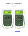
1
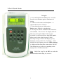
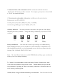
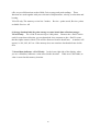
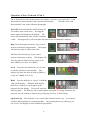
V-Pod and V-Pod II TM Vibration Meter User Manual 10/31/2008 Benstone Instruments, Inc.- 32905 Northland Court- St. Paul, MN 55045 Telephone: 651-386-4425 www.benstone.com Copyright ©2008 all rights reserved 1 Welcome ...............................................................................................................3 What is in the box?................................................................................................5 Specifications for V-Pod and V-Pod II:...................................................................7 General Layout of the V-Pod II: .............................................................................8 Inside the v-Pod & v-Pod II: ................................................................................9 V-Pod II Quick Guide:..........................................................................................11 Display of the V-Pod II:........................................................................................12 Operation of the v-Pod and v-Pod II: ...................................................................15 Using your v-Pod and v-Pod II: ...........................................................................19 Vibration level definitions:....................................................................................20 Setting the Units on your v-Pod & v-Pod II: .........................................................21 Sensitivity adjustment:.........................................................................................22 Calibration and factors: .......................................................................................23 Connecting your v-Pod II to a computer: .............................................................24 How to connect using the USB interface:............................................................25 2 Welcome Congratulations on your purchase of the V-Podtm or V-Pod IItm Vibration Meter. This instrument is built with pride and has features that you will find useful in your measurements. This manual will provide you with all the information you require to get the greatest benefit from your measurement system. Engineers, technicians and maintenance personnel will find that the V-Podtm or V-Pod IItm is intuitive, has an easy to use keypad and is invaluable for route collection, and for vibration measurements. System Contents Your system includes this manual, the V-Pod or V-Pod II Meter, 9 Volt battery, accelerometer with coiled cable, RS 232 to BNC connector, USB to serial converter, and a hard carrying case. Quality Control - Calibration Your system has been calibrated to the highest standards. The V-Podtm or V-Pod IItm has been designed to be rugged and durable for harsh environments. This instrument has rubber seals to protect it from splash and oil in harsh environments. The V-Podtm or V-Pod IItm is calibrated at the factory to ensure that the measurement you are making is accurate and repeatable. It is recommended that your Impaqtm be verified at least once per year for accuracy. Using This Manual In this manual you will find information for using the various features of the V-Podtm or V-Pod IItm. Once you become familiar with the system, you will only need to refer occasionally to this manual for specifications or to certain aspects of operation. Help Benstone Instruments wants to help you get the most from your system. there is anything else we can do, please feel free to call or Email us. Telephone: 651-257-6500 Fax: 651-357-4004 3 If Service or Calibration: [email protected] General information: [email protected] Or you can visit our website at: www.benstone.com The website is the first place to look for product updates, application notes, or technical tips. ICP is a registered trademark of PCB electronics. 4 What is in the box? The V-Podtm or V-Pod IItm measurement kit comes standard with the following items: Fig. A. Fig. B. Fig. C. Fig. D. Fig. E. Fig. F. Fig.G. 1 ea. V-Pod or V-Pod II 1 ea. 9 Volt Battery 1 ea. G-Spike probe and magnetic base 1 ea. Coiled Accelerometer cable 1 ea. Accelerometer 100 mV/ g 50 g range. 1 ea. High strength magnetic base for accelerometer 1 ea. Molded plastic carrying case Coiled Accelerometer cable Fig. D V-Pod & V-Pod II Fig. A Accelerometer with detachable magnetic base Fig. E, F 9 Volt Battery Fig B G-Spike Fig C Molded plastic carrying case Fig. G 5 Options: Fig. H 1 ea. AC analog output Fig I 1 ea. Headset with cable Fig J. 1 ea. Thermometer and cable. Trendex software kit includes (V-Pod II only): Fig K 1 ea. Cable: RS 232 port to USB converter cable. Fig. L 1 ea. RS 232 cable Fig M 1 ea. USB converter software Fig N 1 ea. USB software key Fig O 1 ea. Trendex software on CD Rom AC analog output cable Fig. H Headset with cable Fig. I RS232 Cable Fig. L RS 232 to USB converter cable Fig. K Trendex USB software Key Fig. N Optional Thermometer Fig J RS 232 to USB Converter Software Fig. M Trendex software on CD Rom Fig. O 6 Specifications for V-Pod and V-Pod II: Displacement 0~1999 um, p-p (10~1KHz BP)(0.00~78.7 mil) Velocity 0.0 – 1999.9 mm/s, 0-p (10-1 kHz, ISO 2954) (0.00 – 7.87 in/ sec) Acceleration 0.00~19.99 g, rms (10 Hz HP) Bearing Condition 0.0 ~ 199.9 mm/s (0-p) (1KHz HP )(0.00~78.7 in/sec) 0.00~19.99 g, rms (1KHz HP ) Acceleration accuracy 5% (10 ~ 10 kHz) Velocity accuracy 5% (10 ~ 1 kHz) Displacement accuracy 5% (10 ~ 1 kHz) Battery Indicator Low/ 25%/ 50% / 75%/ full, graphical indicator Sensor bias indictor Normal/ open/ short, graphical indicator Back light LED back light, auto off (10 sec) Sensor Sensitivity (7mV/g ~1300mV/g adjustable) Housing rating IP 65, with EMI protection AC output 2.8V Power supply 9V alkaline battery x1(about 35 hours operation) Auto power off 10 minutes after pressing any key Display 120 x 32 graphic mode LCD Size 180 x 92 x 32 mm(7.1 x 3.6 x 1.0 in) Weight About 300 gram (including battery) Hold function Freeze the display instantly Average function Display the averaged value of the latest 10 data Peak hold function Display the maximum value Gain x10, and increase the reading precision(by 1 decimal place) Displacement w/ Gain 0.0~199.9 um, p-p Velocity w/ Gain 0.00~19.99 mm/s, 0-p(0.00~78.7 mil) Acceleration w/ gain 0.000~1.999 g, rms(0.000~0.787 in/s) Bearing Condition w/ gain 0.00~19.99 mm/s (0-p) (1KHz HP )(0.00~78.7 mil) 0.000~1.999 g, rms(0.000~0.787 in/s) (1KHz HP ) **Memory Up to 1000 points can be stored **Review function Recall and display the saved data **RS-232C Interface Download a pre-defined route form a PC or upload archived data to a PC ** V-Pod II includes Memory, Review function and RS 232 Interface. 7 General Layout of the V-Pod II: Analog output connector for: - RS 232 to printer or computer. - Headphone - Thermometer (used with Trendex software) Accelerometer input ICP type only. LCD display Keypad: 9 Volt battery 8 Inside the v-Pod & v-Pod II: The v-Pod and v-Pod II comes equipped with the highest quality components for accurate and repeatable vibration measurements. In the next sections, we will discuss how measurements are detected, filters and the reasons for having them. How is the vibration values measured? Internally, a (RMS) Root Mean Square detector is used to process the vibration signals. Peak to peak values are computed directly from this RMS value. One of the nice features of the v-Pod and v-Pod II is the ability of the user to select the desired units for measurement, ie. RMS or Peak to Peak (p-p) for example. Because the v-Pod and v-Pod II has smart features, the user can make vibration measurements using their favorite unit of choice. Filters: Each v-Pod and v-Pod II has built in filters to condition a vibration signal. vibration signal whose frequencies are not within the filter range will result in null reading or decreased values. Acceleration: 10 Hz, High Pass filter Velocity: 10 – 1KHz, Band Pass filter (conforming to the ISO2954 Standard) Bearing Condition: 500 Hz to 2 kHz Band Pass Filter Displacement: 10 – 1KHz, Band Pass filter (conforming to the ISO2954 Standard) Note that the filters are forth order, -24dB/Octave roll-off. 9 A Typical high pass filter Typical band pass filter 10 V-Pod II Quick Guide: To begin: 1. Press and hold the on/ off button for 4 seconds. Press the on/ off button again to illuminate the display. 2. Connect accelerometer and headphone or optional thermometer if desired. 3. Select desired test you wish to make; Displacement, Velocity or Acceleration. 4. You may also choose in addition other functions such as hold. This “freezes” the display until the hold is pressed again. Gain will increase the resolution by one decimal place. Avg./ PK (peak) allows you to select either Average or Peak. Selecting Average will slow the display by only displaying average of the last 10 readings. Peak displays only the highest peak value. BRG (bearing) is a high pass filter that filters values below 500 Hz. This means that you will not see anything on the display below 500 Hz bandwidth.* Note: Hold, Gain, Avg/ Pk, and BRG are used with the test mode selected: disp, vel, or accel. 11 Display of the V-Pod II: 1. Bias Indicator status: - OK - Open - Short 5. Hold, Gain, Average or Peak and memory review modes – V=Pod II only 2. Numerical value of the vibration level 3. Vibration units and method of detection 6. Storage location label for point storage or route based data collection storage- V-Pod II only 4. Battery Indicator 7. Stored data indicator V-Pod II only 1. Bias Indicator: The Bias indicator is located on the left side of the display. The V-Pod and V-Pod II continuously monitors the bias condition of the ICP accelerometer and indicates the status on the display. There are 3 conditions: OK, High and Low. OK High Low OK: ICP bias is in the normal range, everything is working correctly including the cable. High: Usually the sensor or cabling is not connected to the meter. Low: The ICP circuit is shorted. Check the cabling immediately. Caution: Do not operate the meter when you observe a high or low bias condition. Inspect and replace as required. 12 2. Numerical Value of the vibration level: This is where the vibraiton levels are displayed for the function you have selected. For example, you may have selected hold to “freeze” the numerical display. 3. Vibration units and method of detection: Availalbe units for each selection: Displacement: um (P-P), Mil (P-P) Velocity: mm/s (0-P), mm/s (RMS), in/s (0-P), in./s (RMS) Acceleration: g (RMS), g (0-P), m/s2 (RMS), m/s2 (0-P) 4. Battery Indicator: The battery indicator is located on the right side of the display, illustrating the battery condition. Change the battery immediately if you observe a low condition. Full 75% Full 50% Full 25% Full Low battery Battery Installation: The V-Pod and V-Pod II is powered by a 9V alkaline battery. When installing the battery, use a screwdriver to remove the batery compartment cover. After installation, attach the cover by fastening the screws with correct torque, since the housing of the v-Pod and v-Pod II is IP 65 rated. Note: The v-Pod II has a built in non-volitle EEPROM that will keep your saved data in memory even if you change the battery. Caution: It is recommended to remove the battery from the vibration meter when it will not be in operation for long periods of time. Alkaline batterys will provide the best performance. Operating the meter in low battery conditions is not advised since the meter accuracy can be degraded. 5. Hold , Gain, Average or Peak and memory review modes: The v-Pod and v-Pod II 13 offer very useful functions such as Hold, Gain, average and peak readings. These functions are used together with your selection of displacement, velocity, acceleration and bearing. V-Pod II only: The memory review has 3 modes: available. Review: All Review : points saved, Review: points 6. Storage location label for point storage or route based data collection storageV-Pod II only: The v-Pod II can store up to 1000 points. Because the v-Pod II can be used for route data collection, you can download via a computer to the v-Pod II a route that has alpha- numeric labels. This will be discussed in more detail later. A number will appear, ie. 001, 002, 003 etc. if the memory does not contain a downloaded route in this area. 7. Stored data indicator- v-Pod II only: In the lower right side of the display, when you see a black bar, indicates a value stored in this location. If this area is left blank, no value is stored at this memory location. 14 Operation of the v-Pod and v-Pod II: The V-Pod and v-Pod II vibration meters are simple to use but yet very powerful. Each function has a distinct purpose and is shown on the display. We will review each function and it’s use in the following paragraphs. ON/ OFF: Press and hold the ON/Off button for 4 seconds to turn on the meter. Pressing the button again will illuminate the display.. The meter will automatically shut off after 5 minutes of idle. Pressing any key will cancel the auto shut off for an additional 5 minutes. Disp: Press the displacement key if you want to measure vibration in displacement. The display will show the units in either um or mils. Vel: Press the Velocity key if you want to measure vibration in velocity. This display will show the units in either Velocity: mm/s (0-P), mm/s (RMS), in/s (0-P), in./s (RMS) Accel: Press the Acceleration key if you want to measure vibration in acceleration. The display will show the units in either g (RMS), g (0-P), m/s2 (RMS), m/s2 (0-P). Hold: Press the hold key to “freeze” or hold the value on the display. When the hold mold is turned on, a camera icon will appear in the bottom left of the display. To turn off, press the hold key again. The hold key can be used together with gain, or average functions. You may also save the reading to memory by pressing the save key. (v-Pod II only) Application tip: This function is very useful when vibration levels vary. An example would be during startup of a rotating machine. By pressing hold every 1000 rpm, you can “freeze” the display at each predefined rpm position. 15 Gain: Press the gain key to increase the display Resolution. In this mode, the vibration signal will be amplified by 10 times. When this mode is turned on, you will observe a gain icon in the lower left display. To turn off, press the gain key again. Application tip: This function is very useful for low level vibration measurement. For example, the displacement level of a precision machine tool is typically within 1 um peak to peak. Caution: When you turn off the gain mode, the reading will take about 5 seconds to stabilize, because the rms detector requires time to average out the previous signal with gain. When using the gain key, the vibration signal will be amplified by 10 times to increase the s/n (signal to noise ratio). converter. Also amplified is the dynamic range of the internal A/D The chart below shows the maximum range readings with and without gain. Units Range with gain Range without gain g (rms) 0.001~1.999 0.01~19.99 mm/s (0-p) 0.01~19.99 0.1~199.9 m (p-p) 0.1~199.9 1~1999 Average/ Peak Hold: Pressing this key once selects the moving average mode. Pressing this key again, selects the peak hold mode. Pressing this key a 3rd time will disable this mode. Average: In the average mode, the meter calculates the average value of the last 10 measurements (moving average) and display the results. This is useful when vibration levels are not stable. The moving average mode will provide a more stable reading by averaging the collected data. Peak Hold: The meter will display the maximum value over time. This mode is used to measure the maximum vibration levels during a transient event. 16 For example, you may use peak hold to measure the resonance vibration level during a start up process. BRG: Press the bearing key to activate the high pass filter. This will eliminate most frequencies below 500 Hz bandwidth. Therefore you will NOT see any vibration readings below 500 Hz. ** The Bearing function uses velocity method of measurement. The available units are mm/s or in/ s. The method of detection available is B-P or B-R. B-P represents “Bearing – 0-Peak” and B-R represents “Bearing – RMS”. **Occasionally you may view some readings below 500 Hz, due to the roll off of this internal filter, but in general, the filter cutoff is 500 Hz. Application tip: Measuring the vibration of bearings can be difficult because of the excessive vibration levels at lower frequencies. Use this feature when measuring bearings to eliminate lower frequencies in your measurement. PREV and NEXT: The Previous and next keys are used to change the active memory address. When the v-Pod II is initially turned on, the number in the bottom right hand corner of the display is the active address of memory. Pressing the NEXT key will increase the number of the active address, while pressing the PREV key will decrease the value of the active address. The number of the address ranges from 000 to 999. You can use these keys to set the correct address when saving data or reviewing the data. Pressing once the PREV or NEXT key will increment the stored value by one. When you press and hold the PREV or NEXT key, you will fast forward or backwards by increments of 10. Review: There are 3 review modes. Pressing the review key once will show the review icon in the lower left corner of the display. Note: You cannot store data in the review modes. 17 In Review Mode 1, you may review the points with no data stored. In Review mode 2, you may review points that has data stored, and in review mode 3: you may review all points. Review mode 1: The first review mode shows a empty square symbol. This indicates the available location points to save data. In this example, there are 100 available locations to save data. Review Mode 2: By pressing the review key again, you will access the second review mode. This mode shows a filed in square symbol. This is an indication of how many points have been saved. A Review Mode 3: By pressing the review key again, you will access the third review mode. This mode shows the letter A along with either 1K or a number. The number listed is the number of points on a scheduled route, whereas the 1K is the default for 1000 available points Save: Pressing the save key will overwrite any data stored in a memory location and automatically advance to the next memory location. If you downloaded a scheduled route, this next location may be a label vs. a point number ie. 001, 002 etc. Note: You cannot save data in the review mode. The save flag left blank indicates that this memory storage location is empty. Press and hold the review and save keys at the same time will clear out the memory. Caution: When you press the save key, you can overwrite existing data. 18 Using your v-Pod and v-Pod II: Sensor Mounting: Each v-Pod and v-Pod II is equipped with an accelerometer with a high-strength magnetic base and touch spike for sensor mounting. The accelerometer magnetic mount is capable of a wider frequency measurement than the spike. The spike is designed for measurement of vibration signals that range below 1 khz. It is always recommended to use the magnetic base where applicable. The touch spike is ideal for non-ferrous surfaces or limited areas. G-Probe: Changing between the spike and magnetic base is easy during in-field measurement. Step 1: Attach the G-Probe as shown to fit the magnetic base. Step 2: Turn the G-Probe to the correct position. Headphones: When collecting data with the v-Pod II, you may use the optional headphone to listen to the mechanical noise sensed by the accelerometer. For an experienced operator, this is a good way to find out the problems of a machine. For example, when a rolling bearing is damaged, it will generate certain pattern of noise that can be heard clearly with the headphones. Simply attach the headphone cable to the 6-pin connector on the v-Pod II as illustrated. Thermometer: The v-Pod coupled with Trendex software allows the data capture of temperature data. The optional thermometer (cable not shown) connected to the v-Pod II will 19 log into memory the temperature. Vibration level definitions: The chart below describes vibration levels for various machine types. 20 Setting the Units on your v-Pod & v-Pod II: The default unit system is set at the factory to be: acceleration= g (rms), velocity = mm/sec (0-peak) and displacement = um (peak-to-peak) respectively. However, you may select your own unit system by the following steps. Acceleration: 1. Press acceleration key to select acceleration measurement. 2. Press and hold the acceleration key for 5 seconds, the units g(rms) and g(0-p), m/s2 (RMS), m/s2 (0-P), will appear cyclically. Release the acceleration key when the desired unit appears. Velocity: 1. Press velocity key to select velocity measurement. 2. Press and hold the velocity key for 5 seconds, the units mm/s(0-p) mm/s(rms), in/s(0-p) and in/s(rms) will appear cyclically. Release the velocity key when the desired unit appears. Displacement: 1. Press displacement key to select displacement measurement. 2. Press and hold the displacement key for 5 seconds, the units um(p-p) and mil(p-p) will appear cyclically. Release the displacement key when the desired unit appears. Once you have set the desired units, the v-Pod or v-Pod II will keep these settings, unless you change them again. 21 Sensitivity adjustment: Each meter is calibrated at the factory prior to shipment, and it is recommended for best results to return the product to Benstone Instruments or an authorized dealer to perform calibration. In the event that in-field adjustments are necessary, the following procedure describes sensitivity calibration. Sensitivity calibration (1) Turn the meter on while pressing the acceleration key. the data collector beeps 3 times. indicated on the LCD display. Continue to press the key until At this time, the calibration mode is selected and Release the acceleration key. (2) In the calibration mode, the definitions of keypad functions change as follows: Displacement key: increase the sensitivity (mV/g) Velocity key: decrease the sensitivity (mV/g) Acceleration key: save the setting (3) Set the sensitivity value according to the attached accelerometer using the keys defined in (2). Remember to press the Acceleration key to save your final setting. (4) Turn the data collector off to complete the calibration process. Caution: The v-Pod and v-Pod II accepts ICP* type accelerometers only. accelerometer must be 100mV/G +- 30% for proper functionality. *ICP is a trademark of PCB piezoelectric Inc. 22 The Calibration and factors: Calibration should be completed Benstone Instruments or by authorized dealers only. Calibration of the v-Pod and v-Pod II is performed via a set of gain factors. Each gain factor is set at the factory prior to shipment. Factor 1: acceleration = gain x 1 Factor 2: acceleration = gain x 10 Factor 3: Velocity = gain x 1 Factor 4: Velocity = gain x 10 Factor 5: Displacement = gain x 1 Factor 6: Displacement = gain x 10 Factor 7: Bearing = gain x 1 Factor 8: Bearing = gain x 10 Adjusting the Factors: Turn the data collector on while pressing the acceleration key. Continue to press the key until the data collector beep 3 times. At this time the calibration mode of accelerometer sensitivity is selected. Continue to press (and hold) the acceleration key again and wait for 10 seconds. The data collector will beep 3 times again. At this time the calibration mode of the correcting factors is selected. Release the acceleration key. Press the “backlit” (on/ off) key to select the correcting factors. The number of correcting factors will appear at the right hand bottom corner when pressing the backlit key. Press displacement key to increase the selected correcting factor (%). Press velocity key to decrease the selected correcting factor (%). Press the acceleration to save the setting. Turn the data collector off to complete the calibration process. Calibration procedure Set all the correcting factors to be 100.0 (%) Install the accelerometer on a shaker, on which a standard accelerometer is installed. The standard accelerometer is connected to a standard rms data collector. Drive the shaker with appropriate sine signal and record the readings of acceleration (x1, x10), velocity (x1, x10) and displacement (x1, x10) respectively. Compare the reading with the standard values that derived from the standard accelerometer and data collectors. Adjust the correcting factors, such that the readings multiplied by the correcting factors will be equal to the standard values. DC offset The calibration for DC offset is not needed because the v-Pod and v-Pod II vibration meter always calibrates the DC offset error automatically when power on. 23 Connecting your v-Pod II to a computer: The v-Pod II can download and upload data to a PC through its RS-232C port. Use the provided D-type 9-pin to 6-pin cable to connect the v-Pod II to the serial port of the PC. Should your PC have a USB port, you will need to install the USB to serial adapter software and cable. Install the USB software in your computer and then connect the cabling to the computer. Use the following communication setting to setup the protocol parameters in the software. For RS 232 Port: Speed: 4800 bps, Data bit: 8 bits, Parity: none, Stop bit: 2 bits RS 232 to USB converter cable RS232 Cable 24 RS 232 to USB Converter Software How to connect using the USB interface: 1. Install the USB – Serial program that is provided. Follow the instructions and then restart your computer. 2. Install Trendex software. Once complete, you are ready to connect your V-Pod II to the computer. 3. Connect the v-Pod II to the computer and attach the USB key to an open USB port on your computer. 4. Next, open up the device manager from your computer. One possible path is: Startmy computer- (right click)- hardwaredevice manager, then select ports as shown. Please note the COM number. In this case, the serial port is assigned to COM7. Noteif the v-Pod II is NOT connected to the computer, it will not display the port setting in the list. 5. Start the Trendex software. In the top menu, select Options- communications. You should see a window like this: In this window, select a communication port that matches what your computer has assigned. In our example, select com 7. Press the “test button” to be sure that the communication port is configured correctly. 25