1
ACCUTRO N
Service Manual
»
7
<
fc
^V
\l'
i
Is
IV
-:-
j.
^
by
L
>
BULOVA
:
1
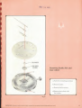
PATENT NOTICE
The ACCUTRON timepiece is manufactured by Bulova
Walch Company, under issued patents as well as pending
paieni appli cat ions, including the Following patent*:
O.S,
Canada
France
GemuuT)
Great Britein
Z.MO,5*2i 3,971.3211 l.l82.uoe; j,it4.«P.:Re.
».2S7.7&t; 3.221.190; 3.262.259; 1.411.1 ia
7M.17B: 756,0ia; 085,410
1.102,373; 74.002: 70,710: 1,401.131:
1.473.153: 1.122,1*3
S71.0SU: 1.096,747; 1,124.413
TBI. 009; 797.051: 84D.DH,- BS4.13G;
-
i:i
H
fi76,*17: &09.081;
953.U9; 1,064.230; 1,074,104
The
SwiUarlaod
Hale
112,299; 333.403; 142.171: 301,311
SI7.879; 5M.3.3; 552.IH52; W1JIB: liw.i::
%V
23.037
fir.-)
amis
Japan
All information
SO.tSS; 50.196
249,102, 3U1.4&5; 4fl=.52G: 3*0. MS:
contained herein
is
2
*«,!«'. ;*ft_31
based on the latest product information a»aitebie at
make changes at any time without notice.
the lime of printing. The right is reserved lo
Capjnprt
£
lft&6. 1969,
Baloa Watch Cosipany,
Inc. ail
"(his reserved.
Table of Contents
Page
To
the
Part
I
Watchmaker
2
-SERVICING PROCEDURES
3
Opening the Case
3
Replacing the Power Cell
4
Regulation
5
5
ACCUTRON" Regulators
How to Regulate
6
Removing Movement from Case
7
8
Movement in Case
-REPAIR OF THE BASIC MOVEMENT
Replacing
Part
II
Special Tools and
9
9
Equipment
ACCUTRON Service Kit
9
11
Cleaning Equipment
Rate Recorder
II
12-13
Diagnostic Chart
Special Points for the
ACCUTRON
Repairman
14
Mechanism—Inspection and Adjustment
Power
Cell
Testing
Indexing
15
19
Testing Electronic Circuit
19
Assembly
Checking the Train for Freedom
Hack Mechanism— Inspection and Adjustment
20
Disassembly
21
Identifying Defective Coil
20
20
_
Cleaning
30
Lubrication
31
32
Reassembly
40-41
Basic Parts List Series 218
Part
III-REPATR OF DATE MECHANISM IN MODEL 218D
Removing Hands, Dial, and Hour Wheel
Date Mechanism Disassembly
Date Mechanism Lubricatinn and Reassembly
Replacing Hour Wheel. Dial, and Hands
Parts List Model 218D
42
43
45
_.
45
46
47
Index
'"ACCUTRON," -BUIQVA." "VfATCKKASTBr aid
48
"Li"
are registered trademarks of Billow
Watch Company,
Inc.
To The Watchmaker,
This Manual provides complete service and repair information for Scries 218
ACCUTRON movements. Perhaps ynu already have experience in servicing ihe 214
ACCUTRON.
which there is a separate service manual. If so. you will fad thai
and servicing procedures for 214 and 21 A ACCUTRON movements
Tor
while Ihe repair
are basically Ihe same. there are physical differences between (he two. primarily
in
the arrangement of parts.
Unlike the 214
ACCUTRON
movemenl, Ihe 218 muvemenlN can be repaired and
adjusted wilhnut Oie use of a microscope. However, those experienced in servicing
nOVCjeeat (and therefore having a Kiutable microscope nvadable). will find
the iniineicope very useful in checking and adjusting 'he 2111 tmli-xinx mechanism.
ihr
/i-i
you have never tmrvlced ACCUTRON. we would like lo poinl out thai the
experienced watchmaker nhoulil ho able lo learn lo service the 210 ACCUTRON
Even
If
a matter of hour* wilh Ihe aid of this manual. Diagnostic procedures
step in
Tor locating and correcting faults are presented on pages 12 and 13. The firs!
movemenl
iu
procedure
using these
RtanQM
Ihin inforiiiatiun
is
lo estuhlish the
cm
symptoms
of Ihe trouble. In
many
he obtained only from the customer. Therefore,
EVER POSSIBLE KIND OUT EXACTLY WHAT THE CUSTOMER'S PROBLEM
BEFORE YOU ATTEMPT CORRECTION,
For example,
let
us assume
that
an
ACCUTRON
in
WHEN
IS
timepiece has been bronchi In you
You must find out whether the gain or loos in
because it
or
more
a week lo determine whether It requires
n few seconds a day or a minute
only simple regulation or whether the movemenl mufil be repaired. Suppose yon
is gamin*; or Inning lime.
are told only llml "it loses" and your rate recorder indicates a loss of. say. 5 seconds
.i
day.
If
customer
you regulate
if
it
accordingly nnd return
ihe timepiece
was
the odicr hand, the timepiece
shown by your
it,
you
will
have a very
dissatisfied
losing several minutes per day (requiring repair)
may have been
rale recorder, In this case,
if
On
losing several seconds per day, as
you elect
to "repair" ihe
movemenl. you
are attempting lo locate a defect or fault Ihat does not exist. Such situations can only
he avoided by finding out from the customer the symptoms Ihat led him
the timepiece lo you for correction.
to bring
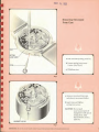
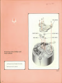
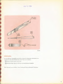
Opening The Case
Use special Inckmy
r
i
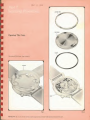
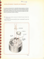
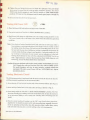
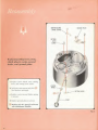
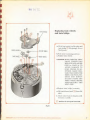
Replacing the 218 Power Cell
a.
Remove case back, using a
suitable case
wrench
to
unscrew
the locking-ring.
COIL FORM SCREW WITH INSULATOR
lorm screw
b.
Loosen
c
Loosen cell strap hold-down
screw, swing cell strap out and
remove Power Cell as shown
coil
CELL
SIMP
(see Fig. 3).
d.
Remove coil form screw
insulator)
POWER CELL
slightly.
and
(with
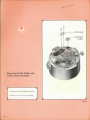
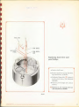
Inspect
cell strap,
(with loupe) under-surface of cell
strap for foreign matter which
may affect electrical contact with
Power Cell. If necessary, clean
with an eraser and dip-rinse.
e.
With the
cell
strap
off.
check
thai
the insulating posl of the cull coil
assembly hus not been damajtr.
1
through improper installation Of
a
Power Cell; attach cell
strap
form
by
mutilator]
through
screw (with its
making
certain
cell
cell strap,
loosely installing coil
strap is correctly positioned
.imund the insulating post of the
cell coil
f.
assembly.
Power Cell with
imprinted side down (see Fig.
Install the
3);
reposition cell strap under tbt
hold-down screw and sccurr
screws.
g.
Check
that case gasket
is
properly
CELL COIL ASSEMBLY
positioned; replace case back
and tighten locking-ring.
Note:
If
sweep-second hand does
not turn, be sure stem is
in the
normal or "in"
position. If so, tap the case
"3" or "9" to
lightly at
start tuning fork vibrating.
Fig. a
MAY
is4
iboy
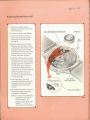
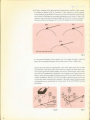
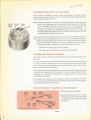
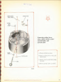
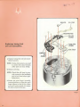
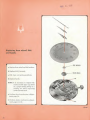
Regulation
THE BASIC ACCURACY OF THE ACCUTRON TUNING FORK IS SUCH THAT
REGULATION FOR MORE THAN A FEW SECONDS PER DAY IS NOT REQUIRED.
CAINS OR LOSSES OF A MINUTE OR MORE A WEEK INDICATE THE NEED
FOR REPAIR. NOT REGULATION.
ACCUTRON
The
regulators
ACCUTRON regulators
(see Fig. 4
J
are serrated to
make them
easier la rotate
and to serve as a calibration.
G3SERVE THE SEVEN
"DMSKWS
Fig.
»
The serrations of each regulator form 7 divisions (4 projections and 3 indentions).
Each of these divisions is equal to 2 seconds per day of correction; in other words,
rotating one of the regulators a distance equal to one division, changes the rate of the
ACCUTRON timepiece by 2 seconds per day. Regulation for as little as
day can be made by rotating one of
lator is rotated can be easily
the regulators V* division.
gaged by reference
to the
Either one or both of the regulators can be rotated in
ple,
a correction of 4 seconds per day can be
divisions, or
made
by rotating each of the regulators
1
/x
second per
The amount
thai a regu-
x
dot on the top of each cup.
making
either
a correction; for
to 2
seconds per day. it
onds per day. even
if
to
2
division.
Since there are 7 divisions on each of the regulators, and since each division
would be impossible
exam-
by rotating one regulator
make a
correction of
both regulators were originally set
all
the
is
equal
more than 28 sec-
way
in
one
direction.
IS
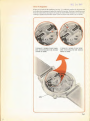
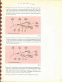
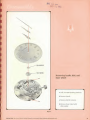
How To Regulate
of the regulators see Fir. 5 a sufficient number of divisions and
necessary to make ihe required correction. Rotating a regulator away
from the center of the movement will cause the ACCUTRON timepiece to run slower:
rotating a regulator toward the center of the movement will cause it (o run faster.
Rotate one or
Imlli
(
)
in the direction
!
m HICULAU ? SECONDS PER DAY SLOWER,
MOVE UMIK REGULATOR ONE DIVISION
OUTWARD AS SHOWN.
f
TO REGULATE 2 SECONDS PfR DAY TASTER,
MOVE EITHER REGULATOR ONE DIVISION
INWARD AS SHOWN
Fig. 5
WAY 24
;3S3
1
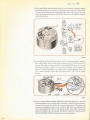
Removing Movement
From Case
stem oat
a.
Pull
b.
Loosen setting lever screw
[setting position].
2 turns. (See Fig.
6.)
c Withdraw stem.
Fig. 6
a.
Remove movement from case
and place in movement holder.
b. Insert
stem and tighten
setting lever screw.
CAUTION: Do
not push
stem beyond point of
engagement with pin on
selling lever. (See
Special Points, item
page
Fig.
IMPORTANT: S«
sore To Indicate model
7
number engraved on movoment whan ordering replacement pans
14.]
2,
Replacing
r~
Movement
In
Case
MAY Bt
'2Q$
Part II
Repair of the
Movement
Be.
Special Tools and Kquipmtrnl
kit
The revised
<li.r "i
mi
I
i!m
ACCHTKON
.mm! lo
i. .-.. |
.'III.
|he following
l.TripU^parpOM
•],-, (ill
2.
Movement Holder
:i.
t.Mikiup-rin);
4. Collet
wrvm
I
2lfl
ACCUTRON
IN
mil-.
|V>.| S.-I
mm
timepiece,
IihIi-iI
(Model GOO)
h
Adjusting Tool
In mldilirm. the revised
sary lo service the 214
Note;
Serv.ie Kit httu the specinl tools necessary lo perform
Mrvioe ihr
ir
you already
:'.l
l
ynir i.,m
The Model COO Test
ACCITKON
ACCUTRON
Service Kit hnn the oilier
(rpei
M
tools neces-
movement
own
hove
it
ACCUTRON
in
ACCUTRON Modal
ACCUTRON Series 210 »tn well
Sendee K it
modified tohandli-
I
lie
for the
Set. illustrated in Fin ID. is ->» BtWrflllftl nnil in servirirn: th-
inovetiii-nl
The
Sel
T-'.l
is
n-qmred
lo
perform Lhree very important
I'unrlians-
i. It
provide* a high reshl i nci voltmeter lochecl the
ventional lov.-re-.i-.UiKT voltmeters
2. Il is
designed to check the currcnl
us
ACCOTRON
Power Cell, (Con-
not suitable Tor thin purpose.)
in the rlei.tronu
eircuil. In indfealQ III
operating
condition. {Conventions! hlgh-rr-sisluno- mirro<niimeiei>. an- mil lettable for this
purpose.)
3.
It
provides an accurate source for the reduced voltages required for the adjust-
ment of the 214 and the 218
[ndaxiBa, t&QehaaiSffle, (The
two voltages are not the
semeO
Note: The Model 600 Test Set
ACCUTRON movements.
is
designed for use with both the 218 and the 214
-
rtpn
DOOT«l
7WTWI
1.
M
A "nest"
Sol
yroridHt
to
hold «
Power Oil during testing. The nest b clearly marked
Power Cell or the 213 Power Cell.
for
proper
insertion of either the 214
2.
A
meter, rending cither volls or
ulCrMUBpWVtt todfc*UU| 'he correct values by
areas marked "OK."
3.
A
-1
position Rotary Swildi lor the selection of the VlrfOUl iMl "'"fliiiutis:
Position i-"t:i n-(
Position 2
Position
ft pi )W1-:k
(
EH"
-"OFF"
:t
Position 4-
"KKAUMICKOAMPKKKS
"LOW AMPLITUDE".
In this position the
appropriate induced voltage for important Indexing
for both the 214
4.
A
and
2111
5.
6.
Mechanism Adjustment,
movements.
2-wire lend, wilh a lab end and a plug end for attachment to the 218
movement and movement
supplier, the
Test Set
ACCUTRON
holder.
A
2-wire lead, wilh a spring clip for attachment to the 214
A
black screw, directly below the center of the
ACCUTRON movement.
movement
dial, for
zeroing the
meter hand.
movement bolder
The Movement Holder
ment and
is
used
electrical jock
10
(Fig.
1
1
)
is
specially designed for the 218
ACCUTRON move-
movement whenever it is removed from the case. The
Movement Holder is used in accommodate the plug tip end of
hold the
on the
the 2-wire lead
Fig. II
to
from the Test Set
:
MAY 24
locking-ring
A wrench,
1969
wrench
designed for opening (he case,
is illustrated in Fig. 12.
Fig. 12
collet adjusting tool
This
tool, illustrated
fingers
II
is
m Fig. 13. is mod
lo
adjust the engagement of the index
inserted in ihe index finger collet or the
pawl
finger collet
and
p.nvl
and gentlv
turned to portion 'he index or pawl Jewel with respfr.l 10 tAO Index wfaaol
Fig.
Ultrannnic rquipment
of the
ACCUTRON
liiiiiir.upprr
is
strongly
recommended
mnvrment The
for cleaning the mechanical BtCttOO
IrdtafteStrna] stefl of the
index wheel requires the
i.i
maximum
320 teelh on ihr beryl-
penetration power available
Olnuonie cavitation generated by nickel transducers The
sonic Walch Cleaner is recommended.
WATCMMASTER
in
ultra-
nit* recorder
The
rale of the
cifically
ACCUTRON
tuning fork can be recorded only on equipment spe-
designed for that purpose.
A special
transistorized amplifier, with suitable
frequency dividers, has been developed by Bulovo engineers lo show this
Tlur.
and
ACCITRON
Rale Recorder
will also
record popular
odd
rate.
heal, spring driven
electric watches.
Note: For further information on the
Power
Cell Tester", the
ACCUTRON
WATCHMASTER
Service Kit. Ihe
ACCUTRON
Ultrasonic Cleaner or the
ACCU-
TRON Rate Recorder, write to
Technical Sales
ft
Services Division
Bulova Walch Company.
Inc.
Bnlova Park.
Ftosbing. N. Y. 11370
'Not shown la this pahBaUan
11
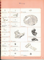
HA
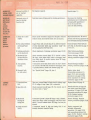
GAINING OR
MAY 24
"'
STOPPED
1.
Crown
in setting
rouD position.
Sweep
second
hand does
not turn
2.
Power
Cell voltage
km.
but fork
hums.
3.
Hack mechanism
out of adjustment
4. Indexing
mechanism out
of
5.
adjustment
Mechanical
inter-
ference with free,
vibrations of fork.
6.
Mechanical
blockage
of train.
7. Dirt in
tooth of
index wheel.
8.
Damaged teeth on
index wheel.
STOPPED
1369
-
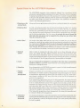
Special Points for ihc
ACCUTRON
Repairmnn
The ACCUTRON movement, br-ing completely different from conventional watch
movements, requires different techniques in its repair. Otherwise, it may be damaged
by improper procedures on the part of the repairman. For example, turning the hands
or the gear train fin either direction) with the hack lever disengaged, will damage
the index wheel teeth or the index and pawl fingers
The repairman's
attention is
called to the following special points:
1.
Removing or Replacing Hands
Always
2.
Replacing Slem
As
crown out
pull
[setting position) before touching the
hands for any reason.
with convrnlionul watches, the stem should preferably be pulled "out" [setting
remove the stem. In replacing
on the setting
lever, the hunk levi-miny btdopEHttd In this bnrtftt t turning the crown will damage the indexing mechanism. For thin reason, do nol push the item in beyond the
point where the stum groove may be engaged by the netting lever pin. before tightposition) before loosening the setting lever
lhestem.il
it
in
pushed
in,
beyond
1
In-
screw
to
point of engagement with the pin
ening the Betting lever screw.
3.
Index Wheel
The teeth on
damaged as u
wheel will not wear away in normal use. nor can they be
any accident, when the movemont is enclosed in its caw (with
The index wheel can only be damaged by improper handling on
the index
result of
the crystal inl.iU].
the pad of the repairman. If It is suspected that the teeth on the index wheel have
been damaged, the moat practical solution ts to replace it. since visual examination
will rarely d Induse the damage
because of the size of these tiny teeth.
4. Electrical
Contact
5. Circuit
Make
a habit of cleaning the
cell strop, which can be done efficiently with an
any while adherent material, if present, from the Power Cell.
Such material may (sometime?] "push" the cell strap away from the Power Cell and
thereby break elect rlcul contact In such instances removing the residue, particularly
on the underside of the cell utrnp will prevent a latent problem in this regard,
eraser, and wiping
i
I
.
ice
ul elei
i-i. .i|
i.-.t
equipment
in proi
rdurcs
uthi'i
than
UMM
:.-i
mmm-mied.
should be avoided. In p.irin ular. circuit elements can be damaged by the use of an
nhinmeter for testing ihe circuit.
6.
Magnetism
Never
fields
7.
demiigiicli/.e
an
ACCUTRON movement or expose
(permanent magnets,
lor
It
to high-strength
magnetic
example).
Magnets
Diagnosis procedures in the preceding servicing instructions have not covered the
Partially
identification oT (rouble caused
Demagnetized
by demagnetized tuning fork magnets, for reasons
of simplified ion. Experience has shown that such trouble is very rare. If the movement current h within the "OK" area of (he scale on the Test Set. the magnets arc
satisfactorily mngnvli/.ed
I
If
the tuning fork
fall to
magnets have
lost
most of their magnetism, the tuning fork will
vibrate and the Test Set will Endicall I very high current-normally interpreted
due to a faulty electronic circuit. If (he magnets have lost only a portion of their
magnetism, the tuning fork may vibrate but the Test Set will indicate that the current is above the "OK" area of the scale In each of these instances, if an excessively
as
high current (and/or failure of the tuning fork to vibrate) cannot be corrected
by
replacing the complete coll assembly— try substituting a different tuning fork.
If
the tuning fork
be returned
8.
Adjustment
of Indexing
Mechanism
14
to
magnets have been demagnetized—the tuning fork assembly must
Dnlova
for rcmagnetizing.
always good practice
to check the adjustment of the indexing mechanism after
and hands. This is because the adjustment of the indexing mechanism can change as » result of the slightest turning of the center second pinion when
the hand is applied.
It is
replacing the dial
MAY 24
:2S3
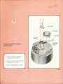
Indexing Mr*;hanisro— Inspection and Adjustment
The checking and adjustment
important to
its
of the
ACCUTROX indexing mer.hanism
extremely
is
operation. This is accomplished by closely controlling the alignment
and the depth of engagement of the index and pawl jewels and
their interrelation.
Details of the step by step procedure necessary to properly accomplish these adjust-
ments are
to
be performed
in
sequence, as follows:
Note: Perform hnck mechanism inspection and ftdjutmenl Ipn&c 2U) before the
following steps.
I.
Ghftdc thai stem
power
ts in
(running position).
Remove
cosing spring (2 screws) and
cell (Fig. 14J.
CASINO SPRING
power
UN
a LI
Ml
S|
CCU SlKAP
HMIHiHIWN
ii;Kl.W
Flg-U
15
2-
The lower surfaces
tive fingers, as
It
of the index
shown
and pawl jewels must be
can usually be accomplished,
if
is
rarely required.
necessary, without breaking the cement attach-
ing the jewel to the finger by exercising
tweezers, close
parallel to their respec-
in Fig- IS. Correction of this alignment
watchmaking
care-
Grasp the finger with
ihe jewel, and press lightly on the end of the jewel or finger
Ira
the proper direction with
Mgwood,
to correct the
alignment of jewel and
in
finger.
Fi«. IB
F<H the proper operation, the two finger*
fingers arc UOftftttSfld
Both o(
p-wels
tin!
papadlCUbu
I
muM
he straight. Obviously, whi-n lbs
disengaged from wheel), there will be n slight CUrVt
itui'ti
he perpendicular to
liir
wheel. Kitlu-r jewel can he
plane of the indr* whucl by grasping the jewel ftagtl
to the
made
i
H
to its pinnini;
point and twisting slightly. iSee Fig.l6.| Centering the index and/or
ptwl |«Wtl
accomplished by alignment ol the
is
wptCtiM post. Cently ItaM the
index Ot p-'wl pnwl by grasping or pushing the end of the post with tweezers or a
suitable screwdriver. (See Fig. 17.) Thin very slight bending of the post will raise
in rel.itinn tu the index wheel.
or lower the index or
pawl jewel
watchmaking care
readjusting the various parts of the
in
Exercise normnl
ACCUTRON
indexing
mechanism.
NOTE.- Index nftMl
(petti
nor
shown
Fig. IB
16
Fig. i-
fiwy
:
3.
^
'«UD
Rotate index finger collet until index jewel completely disengages from index
wheel Observe gap between index gage and index
must not touch the
finger,
finger.
index finger thickness- This, as you will
see. will
make
gap does not meet requirements, bend index gage
proper gap is obtainedIf
INDEX
WHEa
(See Fig. 18.)
The gage
but should preferably be very close, say within one
it
easier
at its
lt>
perform step
4.
attached end until the
HAY 24
7.
1969
cam until pawl bridge is in its maximum clockwise position
(maximum position in the direction lo disengage pawl jewel from index wheel|
The pawl jewel should not be touching the index wheel and nol more than onehalf its thickness away from the wheel. This distance may be adjusted usinc the
Rolale pawl bridge
eoUe) adjusting tool.
BRIDGE
^-~>
PIVOT
SCREW
Index wfceel
teeth nol
f£j\^\
:
i
:\r
I
*
BRIDGE
LESS THAN V,
THICKNESS OF
JEWEL AWAY
CAM
ER0M WHEEL
PAWL
PAWI
8RIUGE
LOCK
SCREW
visible al
this scale
'
Fig at
8-
ii
li
tip
i'hij:
tip of other
the
nrr.1
fork
<.l
alnrt.
id
Teal Sei. turn
nii.iry
IVr.l Sri.
Should
i
" « "I ikt
•trap as
undo
shown
movement
holder. Insert
in Fig. 21. Will
lull
tD 10
"LOW AMPLITUDE" position If tuning
Bg will hr indicated on
WVOM
switch to
mil tkcgin to vibrate,
iIim".
ui.li-r
of Test Scl lead into iSu
lead of Test Set
ofl
Ihin OOOUT,
Up HMVtntM
holder lightly and fork will
Current ruiuling will then drop to the lower end of "OK"
m
jr«-j
r.lighlly
|h'1i»W
COPL fORM SCREW
JACK
PLUG
CELL STRAP
TIP
i
9.
Rotate ihe pawl bridge
maximum
cam VERY
SLOWLY in either direction (since
it
movement hegins
to run.
::i
war. at its
distance awny. rotating either clockwise or counterclockwise will
the pawl jewel toward the wheel) until
n-
move
This can be seen
visible. TURN THE CAM FARTHER IN
THE SAME DIRECTION UNTn. THE TRAIN STOPS. AND THEN* CONTINUE
STILL FARTHER UNTIL YOU REACH THE POINT WHERE IT STARTS AGAIN
AND CONTINUES TO RUN (Momentary hesitation permissible
merely by watching the wheels thai arc
)
IB
HAY 2 4
pawl bridge lode screw and check (he lightness of the
pivot screw, to assure that the bridge is rigidly clampod in position.
10. rifthtcn Ihe
TRON
13.
tf it
2.
3.
10).
Disconnect the Test Set frum the movement.
Place the
Power
""
Cafl
Cell (with yellow seal up) in nest of Test Set.
Turn rotary switch on Test Set
to
"CHECK POWER CELL"
Read Power Cell voltage on right-hand
"OK"
•
The ACCU-
does not. the adjustment must be made again (steps 7 through
Taring 218 Power
1.
pawl bridge
"LOW AMPLITUDE"
train should continue to run (Test Sel switch at
position),
7969
area of scale
The voltage raiding should be in the
Power Cell is in satisfactory operating
scale.
.25 to 1.45 volts) IT
(1
position
it is.
(•minion.
Note: Poor electrical contact between Power Cell and Test Sol will
cause either |
low reading or a wavering indication of cell voltage. It can be readily
vofdfld
by making certain that Power Oil surfaces and contacting points of the Twit
Set neat and clip are clean. Rubbing Of twitting a suspected
cell between the
contacts while checking voltage la gnod practice A wavering reading
ol
age is always an indication of pool Contact, DO) an iml
ion of a had celL
Testing should always be done with the authorized ACCUTRON Test Set or
wilh a high-resistance voltmeter (hnvtng nol lens than 10,000 ohms per volt
crudtivity), such
u the ACCUTRON Power Coll Tetter""ACCUTRON
Caution: Never use substitute cells in place of the genuine
OH. Though
this
other cells
may
model timepiece and Bay,
movement The
2IB"
|w
,- t
look the same, they will not reliably operate
in
some
only correct Power Cell
instances, seriously
b« 'ACCUTRON
damage
the
210" imprint
(sec picture above).
sling
Klnctmi
;ii1
The following procedure is performed with the Power Cell
and the movement positioned In Ihe movement holder.
1. Insert
other lead of Test Set under
Turn rotary switch on Test Set to
cell strap
as
shown
"READ MICROAMPERES"
Set meter should give a reading of current on left-hand scale.
to lap
Tent Set
plug up of Test Set lead inio the jack of the movement holder. (See Fig, 21.)
2. Insert tab tip of
3.
in the nest of the
movement
(It
lightly to start tuning fork vibrating after
in Pig. 21.
The Test
may be necessary
position.
connecting Test Set
leads.)
4.
Observe current reading.
If reading is in the "OK" area of scale (tl.0 lo
10,0 micromovement with indexing mechanism engaged) electronic
amperes
for the dialed
circuit is
operating satisfactorily. Bare fork operation [that
fork and coils only}
'Not shown in
litis
may give
a current
is pillar plate,
tuning
reading as low as 6 microamperes.
publication
19
Assembly
Identifying Defective Coil
is intended to identify which coil assembly is defective, when a
check of ihe movement current results in a zero current reading, indicating improper
This procedure
I ii ii r.
cnm&n
con
uw> strip
sea*
oil ox
too*
tinning of the eJectrunic circuit.
Note: Mechanical interference, caused by improper adjustment and/or any factor
(such as lint} which restricts or work-loads the fork may result in abnormal
is "open" (current reads zero), it is rarely
I!
assembly during repair of ACCUTRON.
the tuning fork vibrates, an ACCUTRON problem is not due to a faulty coil
assembly. Higher than normal current or variable current are (with very rare
exception) al waya caused by other factors.
Tesl Set readings. Unless the circuit
necessary to replace the
cuil
Assuming the Power Cell has been checked and the Test Set properly connected to
Ihe movement, yd bhfl meter indicates zero current, perform the following simple test:
Remove the plug-Up lead from the |ack in the movement holder and touch it
to the lead strap
may be
coll
screw between the two
identified
a.
Remains xero— Replace
b.
Becomes excessive-Rep ace
•
pa
heck
the cell coil
I
Checking Ihe Train
This
in
h'i.mI
to il.ti-i
coil assemblies.
The defective (open)
by whether the current indicated by the motor:
assembly
compnnent
the
coil
assembly
for I-'reedom
nunc whether there
is
any mechanical blockage of the
ti.im
The
roonl scnnftlvp .mil convenient
M
twang" the
line;
method of checking the
train
is to
pluck,
atlachod.
When
freedom
of the tuning fork to which the index finger
is
this in done, the fork will vibrato for a few seconds and this motion will be trans-
mitted to the train— if
The motion
any of the wheels
of the Iraln can easily he seen by watching
that the fork is
j*
not blocked.
it is
being plucked.
plui kril, this in
evidence
If
ol n
no motion of the gears
blocked
train,
Is
apparent
at the time
when
the fork
assuming that the indexing linkage
ban already been nliecked.
Tin-
freedom of tho
train
may BUM bo checked by simply moving one
of the whreln
with a tweezers or needle with both pawl and index collets rotated lo disengage the
respective jewels from Ihe index wheel.
Hack Mechanism
INDD
PAWL
NHEa
FINGER
Inspection and Adjustment
1.
Pull stem out (setting position).
2.
Pawl jewel should be from
PAWL
Lin PIN
thickness
away from index
Fig. 22.) If
pawl
Fig.
2Q
22
lift
*4 lo 1
Jewel
wheel. (Sec
necessary adjust by bending
pin
L
MAY
u
.„^
r
\
'/•
;
'^.
DIAL
WASHLR
HOUR
Wilt
I
Removing hands,
hour wheel
a. Pull
b.
slum oul
Remove hands.
IMPORTANT;
H- nirs to Ideality mode! stamped cm movement
when
screws).
Remove hour wheel with
dial
Fig-
and
(setting position]
c Remove dial (2
d.
dial,
washer.
23
ordering replacement parts.
21
*
1
A
CASK
SPRING
power cat
COL
SIRAP
CELL STRAP
Removing power
cell
and
hold
down
casing spring
a.
Loosen
cell strap
screw and
b.
form screw.
Turn cell strap counterclockwise
and remove power cell-
c Remove
22
coil
casing spring (2 screws).
HOLD-DOWN
MAY 24
1363
3
INDEX COLLET
PAWL COLLET
Disengaging index and
pawl fingers
a.
Push stem
b.Use
in (running position!.
collet adjusting tool to rotate
index and pawl fingers
away from index wheeL
Fig.
i
a
23
TRAIN BRIDGE
FOURIH WHtEl.
SECOND WHEEL
INDEX
Removing
Irain
train
WHEEL
bridRK and
wheels
a.
Remove
train bridge |4 screws).
b.
Remove
train wheels.
Fig.2fi
v
INSULATOR
1
w
CELL STRAP
i
"
CELL COIL
ASSEMBLY
TUNING FORK
ASSEMBLY
Removing tuning fork and
FORK SPACER
coii
assemblies
COMPONENT
COIL
ASSEMBLY
a.
Rotate pawl finger assembly clock-
wise 180 degrees to clear timing
fork and pawl bridge pivot screw.
b.
Remove tuning
fork and coil
assemblies (6 screws).
CAUTION: Do not pry
at
tuning fork.
to
base of
Use
a
punch
push tongue of tuning
fork through push-oH
hole on dial side.
c Note position of fork spacers.
FINGER
Colors denote different thicknesses.
Fig. 27
aili
25
HACK LEVER
PAWL BRIDGE
HACK LEVER
SPRING
PAWL BRIDGE
CAM
Removing pawl bridge and
hack lever
a.
Remove pawl
(2
b.
bridge and
cam
screws).
Remove hack
hack
lever
and
lever spring.
Fig- 23
26
MAY
2 1 'WWW
7
r
YOKL
SETTING WHEEL
ClUTCH LEVER
MINUTE WHEEL
CLUTCH LEVER
SPRING
Removing yoke, clutch
lever, and setting and
minute wheels
a.
Remove yoke
fa.
Remove clutch lever spring
and clutch
(1
screw).
lever.
c Remove setting wheel
and minute wheel.
Fig. 29
.
27
_--.
FOURTH BRIDGE
CENTER WHLEl
ASSEMBLY
Removing fourth bridge and
center wheel assembly
a.
Remove
fourth bridge (2 screws)
b.
Remove
center wheel assembly.
Fig.
30
A £oa
CENTER SECOND
BRAKE SPRING
\
GROUND PLATE
11" V,
LEVER
.'-.-:.'.
Removing
setting lever,
stem, clutch wheel, center-
second brake, and
ground plate.
a.
Remove setting
b.
Remove
lever screw.
WHEEL
SLUING LEVER
setting lever, stem, and
clutch wheel.
c.
Remove center-second brake
(1
screw
spring
|
ARemovc ground
plate
[1
screw).
Fig. 31
(lUiLMit para.
29
J
Cleaning
cap jewels in jeweling devices with spring-held cap jewels from pillar
plate and tram bridge. After cleaning, replace cap jewel assemblies.
Separate
all
quipim-nt
Ultrasonic
The
practice of cleaning a con-
ACCUTRON
in
necessary for cleaning the
movi-iiieni should be treated exactly as
vnnlional watch, as a routine pari
one exception. The electronic
of nearly every repair, results
be cleaned
from the watchmaker's knowl-
parts.
Sdgt
and
(Ji.it
can be expected
when lubrication Is fresh.
The performance of ACCUTRON
relatively unaffected
by the con-
dition of the lubrication. Cleaning
will not usually be required to re-
store an
ACCUTRON timepiece to
proper operating condition
cleaning
is
mation an
fine
movement. The
watch movement, with
tuning fork and the pawl bridge should not
equipment, because of the possibility of damage to delicate
optimum performance
reliability
only
is
in ultrasonic
circuit, the
ACCUTRON
any
When
The
tuning fork, colls, and pawl bridge can be cleaned satisfactorily by merely dip-
ping into a "benzine cup" and thru placing 00 > tissue to dry.
Care should be taken to prev.-nl DUHil chips, which may be present in the cleaning
cup or on the bench, from being attracted In the permanent magnets on the linn of
the tuning fork. Inspect the fork carefully after cleaning, anil
any
particles
linging (• thi
ih.ii
NO PARTICLES SHOULD
IIK
LEFT
if
this
has occurred.
mtgDtto can be removed with masking tape.
CUNCINC TO FORK MAGNETS.
necessary, the infor-
tbi*
p»ko
is
applicable-
center whei'l .muenibly [cannon pinion with center whcell should not be token
The
apart, but cleaned
an n
unit.
Aftur cleanimt.
tin-
whirl should not be rotated
until
properly lubricated. (See reassembly instruction Page 33.
Tin- index
wind
!,,!li
I
required special handling care in cleaning to prevent
of this purpose,
it iu
damage
io the
necessary tu use a suitable tool to grasp the index
wheel pivots when imtmTrung the index wheel
HANDLE TUB INDEX WHEEL HY THE
RIM-
in
the ultrasonic cleaner.
NEVER
GRASP THE PINION ONLY
A mi table holding loot for cleaning the index wheel can easily be fabricated by
modifying an ordinnry pair of watchmaker's tweeter* made of brass or Othtl "<"'
magnetic material. || follows:
L.
Spot
2.
Bend
drill the insider, oi the
a piece ol stiff
be used as a clamp.
tweezer tips as shown
in the
upper section of
win- around the tweezers and form the wire so
One end
of the wire should
that
Fig, 32.
it
can
be placed between the tweezer
tongs.
1 Check thai wire clamp locks tweezer tips progressively closer together as clamp
is
pushed towards the
tips.
Note: Authuri/rd Material Distributors can supply,
Wheel Holder
30
illustrated tn
at
lower section of Fig.
nominal cost, a special Index
'
B
SPOT DRILL
(2 PLACES!
INDEX
WHEEL
<K
CU
"^"j Ngf
Yin.
a
Lubrication
In ihe following
rsquiHd
fbl
the
reassembly
ACCUTROX
proci:cliirv'..
taporlaal lubrication instruction:! nrr
Series 218. TlttM Mfl
H
follows:
®M«'.-!-iit I niji'i-Syi.u Vtaeo Lube
(M)Mo«-btu5 OL207-SpKrirtl Lubrfflal With Molybdenum
Both lubricants
-ire
Dlflulfldfl
available at your Authorized Bulova Maleritils Distributor.
31
r
CENTERSECOND
BRAKE SI
GROUND PUTE
SETTING
LEVER
SCREW
Replaciny setting lever, stem,
clutch wheel, renter-second
brake, and ground plate.
.Replace clutch wheel, ttfito, letting
lew, nM'l letting lever suraw.
.huich
b. Lubricatr- Hi-
Use
m square
and
pilot
M
lubricant sparingly
SETTING LEVER
c Replai-e
(l
d.
center-second brake spring
tcrew].
Replace ground plate
(1
scrrw).
Mocbius OL 207— Special I.nbricant
Molybdenum Disulfide
with
Fi S 33
.
32
IA
—
FOURTH BR1DGJ
tfNIERWHIH
ASSEMBLY
Replacing tenter wheel
assembly and fourlh bridge.
a.
Lubricate center Wheal ai.M-mbly
and center tube
.'M\
Use lubricant
sparingly.
b.
Replies center wheel assembly.
c Replace
fourth bridge (2 screws).
Mocbins OL 207-Spccial Labricanl
wilh Mnlvbdcnum Disulfide
Fig.
4U
iPi^.ii.i-iiniL'
.
34
-iii;s,»in.j(
-Jill
33
4
VOKE
Replacing minute and
setting wheels, clutch lever,
and voke.
SETTING WHEEL
MINUTE WHEEL
—
~Sfe
CLUTCH LEVER
CLUTCH LEVER
SPRING
a.
Lubricate minute wheel pivot and
selling
wheel post(Mj Use lubricant
sparingly-
b.
Replace minute wheel and setting
wheel
c
Replace clutch lever and clutch lever
spring.
screw).
d.
Replace yoke
e.
Lubricate yoke(M)
\1
>: Moebius OL 307-Spccial Lubrican!
wi!h Molybdenum Disulfide
CAUTION:
If
clutch lever is replaced
upside down, damage to
indexing mechanism can
result.
FiB.35
:i-i
i
r
HACK UVIR
\
/
CAWl BRIDGE
HACK LEVER
SPRINli
PAWL BRIDGE
CAM
Replacing hack lever and
pawl bridge.
a.
Roptecc hack
b.
Replace hack lever spring wilh short
leg toward liiver. as shown,
c.
Lubricate Slem pilot
lever.
V
where
it
touches hack lever. Use lubricant
sparingly.
d.
Replace pawl bridge and cam
(2
screws)
Moebius OL 207-SpeciaI Lubricant
with Molybdenum Disulfide
Fig.
M
35
r
ISOLATOR
CELL STRAP
INSULATING POST
COL
Replacing tuning fork
COIL
TUNING FORK
ASSEMBLY
and coil assemblies.
'FORK SPACER
COMPONENT.
COIL
ASSEMBLY
a.
Replace toning fork and coil assemblies [6 screws).
NOTE: Tuning
fork spacers are used
lo center fork tines
pillar plate
b.
Replace
and
between
train bridge.
cell strap.
NOTE: Check
that cell strap
erly centered
on
is
prop-
the insulating
post of coil form before tight-
ening screw.
c Rotate
the pawl finger assembly
counterclockwise to bring the pawl
finger adjacent to the
lift pin. Index
and pawl jewels should not engage
the index wheel at this time.
Fig.
•A,
37
MAY 24
'''.
Replacing train wheels
:-i.;ge
and
a.
train bridge.
Oil all cap jewels in pillar plate
train bridge
FOURTH WHEEL
V
Oil sparingly.
and
Do not
flood jewels.
SECOND WHEEL
b.
Pnsh stem in (running position].
c.
Replace train wheels,
INDEX WHEEL
CAUTION: MAKE CERTAIN THAT
PAWL FINGER HAS
BEEN ROTATED AS PER
STEP 5c. PAGE 36 TO
AVOID DAMAGE TO
PAWL FINGER- IN ADDITION. MAKE CERTAIN THAT BOTH THE
INDEX AND PAWL FIN-
GERS ARE DISENGAGED FROM THE
INDEX WHEEL BEFORE
PERFORMING THE
NEXT
STEP.
d.
Replace train bridge (4 screws).
e.
Oil fourth lower jewel v) (from dial
side).
f.
Chock wheel
train for
freedom with
tweezers or needle.
Moebius
OL 219-Synta Visco Lube
Fig. 38
DriraETA.N
37
Mm
r
Replacing hour wheel,
and hands.
dial,
a.
Replace hour whrcl and dial wnnher.
b.
Replace dial
c
Pull
d.
Replace hands.
NOTK:
(2
screws).
stem out [setting position).
It
is
necessary to support the
center second upper cap jewel
on a proper
staking set
fitting
stump
when
in a
replacing
center-second hand.
e.
Perform hack mechanism adjustmrnt. page 20.
f.
Perform index mechanism adjustment, pages 15-18.
Fig.
38
39
MAY 24
1969
CASING SPRING
la\
power cai
CELL STRAP
COIL
FORM
SCREW
CELL STRAP
Replacing casing spring
HOLD-DOWN
SCREW
and power
cell.
Replace casing spring
(2
screws).
b.
Replace power uell [imprinted
down, yellow sea) up).
c.
Tighten
cell strap
and
coil
side.
form
screws.
Fig.
Replacing movement
V
9
See page
8.
ID
in case.
steps 1 and 2.
.
Regulation following repair.
10
IV
After the movement has been replaced in the case, always check regulation (adjust if necessary)
to assure that the rate of the cosed timepiece is approximately two seconds per day slow, in dial
up position. The most convenient method is to use the Rate Recorder (see page 11) Otherwise,
be certain that an accurate time source is used for checking true 24-hour rate.
49
MA:
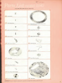
series
218
a
03
Secund Wheel iad Pinion
1
22
Bridge
INA
Coil, uuil
Fork Fool
liiiiC,
Hole Jewel and Setting
Pawl Bridee Sub-Aiirrably
a
ZB Tram
Bridjtc Screw.
Pawl Bridge Lock Screw
Third Wheel Assembly
159D
182
spcaft
pawl Unas*
Cam
.
I
106
40
Oolr-rTubeAssesbljr
Cenlrr Second Hand
(To Suit Dial)
I
.,
•?
7
Tuning Pork Screw
Fourth Wheel ins Pinion
*
Cell Strap
162
Power
Mmuic Hand (To Sail Dial)
167
Lower Jewel for Fourth Wheel
186
Fork Spacer
lOO
Upper Bushine. (or Third
4iid Fourth. Wheels
202
Clutch l-nver Spring
184 Pawl BndRi'
Col!
Piv.it
Screw
&
tOfl
1
Outer Wheel Asscably
Hour Wheel
'
Hour Hum! (To
^
111
Minute Wheel and Pinion
Suit IJiol)
d
I
5
148
DiilScrvw
203
1118H Cap Jewel
Yoke
^
\
1
i
1
2
Ind«"»
Wheel and Pinion
1
T> I
Curl
Form Screw
1 68C" Hole Jewel and
Scttins
204
Clolch Lover
H
•
119
Upper and IJiwer
iiur-liitiK fnr Index
Second Wheel);
ad
Settm* Wheel
1G8D
Sprin*
205
Settinii
Lever
a
1
—
I
Center Second Brake Spring
I59B
Cap Jewel
176 A
Replacement spare parts can oe ordered from your BuJova Materia! Distributor.
40
Setting St
207
dutch Wheel
a
w
MM
Selling Lever
Screw
liack Lever SprinE
209
211
Jr:
3 19 A
'
'
;
00
-'•-
1969
Fourth Bri.lee
>
-.::-;-.- :: - -
/
Ground
24
1
212
Plate
320
Casinc Spring Screw
sn
r
21^
Sjiccial Train
321 C«nl« Swwnd
Screw, Ground
Pln'r.
ScTRW
llrakp
Sprinc Screw
I
Pillar
Wale
J
Hack Lever Assembly
—***'
1$^*
Indo
FirtRcr
Assembly
-'jmponenl Coii Assembly
~«JU
404
Pawl Fingiir Assembly
"13
Train Bridee
"*
s
Ho Id -down Screw.
Lead
Cot)
Si rap Sen-
Assembly
S
s
304
Cell Strap
Cell Coil
Lead Sund-Oil
v
8
60SB
Kourth Bridge
S.«w
Coil Lead Sland-Off
BosninR
*
Tuning Fork Assembly
V
Volte
Screw
Ml
814 A
B10
Coll Strap
Stand-OS Tube
IMPORTANT: S« sort lo
indicate model
S
J
number engraved an aovemeat when ordering replacem ent parts.
41
--
Part III
Repair of Date Mechanism
in
Model 218D
All information
and
instructions contained in Parts
arc also applicable to the Model 21BD
1
ACCUTRON
and
II
manual
of this
(Date Model), with the
following excepti unit.
IMai!:. Tor disassembling, lubricating,
are given
and ro-nnsembling the date mechanism
Ihe .icciinpanyinj! illustrations. For
in
all
other detail-, concerning
service und repair instructions for Ihu basic Series 218
ment, refer
The
parts
used
.ire
in
to l*ari
lint
included
When
Model
Section
list
lists
the replacement parts
which are
does not repeat replacement purls
Haste. Parts List in Part
thai
II
ordering replacement parts, be --urn to indicate that the ports are far
2181).
Pot example,
208. write the Pari
42
this
Model only. The
in tin-
move-
H.
contained in
the Dale
ACCUTRON
Number
if
you are ordering a new clutch wheel,
as follows: 218D208.
Pari No.
MAY 24
DIAl
IS
WASHCR
HOUR WHEEL
Removing hands,
hour wheel
ASSEMBLY
a. I'ull
dial,
slem out (setting
and
position).
b.
Remove hands.
c.
Remove dial
d-
Remove hour wheel wilh
dial
[2
screws).
washer.
n* a
IMPORTANT: Be
rare lo indicat e awle)
number *ngnv*d on movement when ordering nplacenivni
pvU
•13
MAY
-
date trip
sprwg
t
:-"[
:;-::-:
>
'OWE INDICATOR
,*?*•
i
>s,
DATE INDICATOR
TRIP
ARM
-DATE TRIP
WHEEL ASSEMBLY
DATE INDICATOR
DETENT-
DATE CORRECTOR
DATE INDICATOR
DETENT SPRING'
DATE CORRECTOR
DETENT
zr.-
•
STEM
Fig-
4-i
.
Date Mechanism Disassembly
r
a.
Remove dale
spring by collapsing open end sufficiently
trip
arm until loop end is
then be withdrawn from date bridge.
rece«8
b.
nhovr
trip
Remove date
bridge
Caution:
with care
Lift
clear of
its
tO slide into
recess. Spring
may
screws)
(3
to
avoid loss of date Indicator delenl spring
c Remove date indicator detent
spring, date indicator detent and date
Indicator.
arm and date
d.
Remove date
e.
Remove stem
r
Remove date corrector detent
trip
(See Procedure
trip
I,
wheel assembly.
page
8],
and date corrector.
screw]
\i
Date Mechanism Lubrication and Reassembly
av
Replace date corrector doteal
b.
Lubricate and rephnr dale
(i
screw).
nrreclnr with stem and
•
Rcansembly and Lubrication. Procedure
c Lubricate date
trip
and date indicator
d. Oil dale trip
a.
arm
1,
page
wheel pivnl "''and replace dale
trip
pin
'
arm Use
l).tJse
dutch wheel. (Soo
HZ.)
Irip
wheel assembly
lubricant spaiine.ly.
3
lubricant sparingly
Replace date indicator, date Indicator dataal and data indicator detent
spring
t.
Replace date bridge
Note:
(3
screws).
Make certain dale
trip
arm
is
nnt trapped
between
pillar plate
and
date bridge before tightening screws.
g-
h.
Apply a small amount of lubricant
which engages date trip arm. Use
Replace date
trip
'•:
In
lower end of dale
trip
spring
lubricant sparingly.
spring by collapsing open end sufficiently to permit
above date trip arm. then slide loop end
making certain that upper end nf spring snaps into cutout.
insertion into date bridge recess
into its recess,
i.
Lubricate date indicator trip
Muebius
IMPORTANT
.
5-
s
:
OL 207 - Special
arm
'!..'.
Use lubricant sparingly.
Lubricant with
Molybdenum
Disulfide
para
45
.
4
=
;•
Replacing hour wheel,
and hands.
dial,
a.
Replace hour wheel and dial wnsher.
b.
Replace dial
c
Pull
DIAL
[2
WASHER
screws).
BOURWhm
stem out
(setting position), ad-
ASSEMBLY
vancer dial train slowly forward until
dale indicator jumps to the next date.
cL
Replace hands exactly
NOTE:
It
is
necessary
12 o'clock.
at
lo
support the
center second upper cap jewel
on a proper
fitting
staking set
stump
in a
when replacing
center-second hand.
e.
f.
Perform hack mechanism adjustment, page 20.
Perform index mechanism adjustment. pages!5-18.
Fig. 43
46
u'.
All other parts
I
same as basic
series
218)
cT
^
c--ic*~»
<P
2UB
clutch
9
wh<d
X
20
V\
^&&8Je5^
:I0S Dale Bridge Screw
-71; Data
linlii.ii.il |S| ( .-.ilv
Ih.n ^[>rriur»«nJ
Crown location!
.
t).Jr
Corrector Dclcul Scwrw
ll
Cciilur
Whoul
Aunpiiiljly
-•
4
569
Dnlr
flHM Minute
(
Wli-.-l Aa-.-irihU
•
I
).»",
Li"
/
/
"<K1
Dii«hTn[i
582
II. it..
B0fl
Qah 'indie
Arm
y
i'..|iS|irlt>K
HourwhMl Amiably
x,
I
..
9
.v ImlicaiorDatent
f
»*
o
to*
ll.ff-
Indicator
DetaolSpniw
X
709
i Dale Trip Wfcod \--'-nnlily
IMPORTANT:
Be
--tirt Ii»
indiaU model cumber
tfnjrnved on
Pillar
J'lati;
movement when ordering rcplacemcnl parts-
47
&*
•
Index
Dial
Removing, Basic 218 21
Removing, model 218D 43
Adjustment, indexing
mechanism 15
Replacing, Basic 218
38
Replacing, model 218D
46
Disassembly 21-29
Disassembly, Date mechanism 45
Casing spring
E
Removing 22
Replacing 39
Rlcctronic circuit, testing 19
Case, closing 8
opening 3
Center-second brake
Fourth bridge
Removing 29
Removing 28
Replacing 33
Replacing 32
Center wheel assembly
Removing 28
Replacing 33
Circuit, testing
G
Ground plate
Removing 29
19
Cleaning 3D
Replacing 32
Cleaning equipment 11
Clutch lever
Removing 27
H
Hack lever
Removing 26
Replacing 34
Replacing 35
Clutch wheel
Removing 29
Replacing 32
Hack mechanism
Inspection and
adjustment 20
Coil and tuning fork assemblies
Removing 25
Hands 14
Replacing 36
Removing, Basic 218 21
Removing, model 21 8D 43
Replacing, Basic 218 38
Replacing, model 218D 46
Coil assembly, identifying
defective 20
Collet adjusting tool
11
I
D
Removing, Basic 218 21
Removing, model 218D 43
Date mechanism
Disassembly 45
Lubrication 45
Reassembly 45
Replacing, Basic 218 38
Replacing, model 21 8D 46
Date mechanism, repair
of
42-46
Diagnostic chart 12-13
48
lour wheel
1
Index and pawl Bnger
Disengaging 23
Index jewel 16,17
...
Index
Index wheel 14.30.31
Indexing mechanism 14. 15-18
Service kit
9-11
12-13
Servicing chart
Locking-ring wrench
Lubrication
Selling lever
1
Removing 29
31
14,
Replacing 32
Dale mechanism 45
Selling wheel
M
Removing 27
Replacing 34
Magnetism
14
Microscope
2,
Spedal
14
point!.
14
Special tools and
Minute wheel
Removing 27
Replacing 34
equipment 9 11
Stem M
Removing 29
Replacing 32
Mod*l21BD
Movement
All-Af,
Removing Tnim case
Replacing
in
Site:.;.
limil'TU
17
7
case H
Mnvirmirnl holder 10
T
Test set
9.10
Tool, for cleaning index wheel
Paris
list
Basic 218
40.41
Train bridge and Iraiii wheels
Removing 24
Replacing 57
Model 2180 47
Tram, checking
Pawl bridge
for
freedom
Removing 20
Trouble symptoms 12-13
Replacing 35
Tuning fork and
Pawl jewel
Power cell
16.
coil
20
assemblies
Removing 25
18
Replacing 36
Removing 22
Replacing 4.39
Testing 19
u
Ultrasonic cleaning
11.30
w
Rate recorder 11
WATCHMASTER products
Reassembly 32-39
Reassembly. Oate mechanism 45
Y
Regulation 5.6
Regulation following repair 39
Yoke
Removing 27
Regulators
5
Replacing 34
11
31
I
I
I
mthiio
IB u. I. ".