1
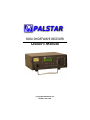
R30A SHORTWAVE RECEIVER
Owner’s Manual
© Copyright 2008 Palstar Inc.
Printed in the U.S.A.
2
Important Safeguards
An appliance and cart combination should
be moved with care. Quick stops, excessive force and uneven surfaces may cause
the appliance and cart combination to
overturn.
WARNING: TO PREVENT FIRE OR
ELECTRICAL SHOCK DO NOT
EXPOSE TO RAIN OR MOISTURE
The lightning flash with arrow head
symbol, within an equilateral triangle, is
intended to alert the user to the presence
of uninsulated “dangerous voltage” within
the product’s enclosure that may be of
sufficient magnitude to constitute a risk of
electric shock to persons.
The exclamation point within an equilateral
triangle is intended to alert the user to the
presence of important operating and
maintenance (servicing) instructions in the
literature accompanying the appliance.
WARNING: TO REDUCE THE RISK OF FIRE OR ELECTRIC SHOCK, DO NOT
EXPOSE THIS APPLIANCE TO RAIN OR MOISTURE. DO NOT
OPEN THE CABINET WHILE OPERATING. REFER SERVICING TO
QUALIFIED PERSONNEL ONLY.
CAUTION: TO PREVENT ELECTRIC SHOCK, DO NOT USE THE THREE WIRE
CORD WITH AN EXTENSION CORD RECEPTIACLE OR OTHER
OUTLET UNLESS THE BLADES CAN BE FULLY INSERTED TO
PREVENT BLADE EXPOSURE.
1. Read Instructions—All the safety and
operating instructions should be read before
the appliance is operated.
2. Retain Instructions—The safety and
operating instructions should be retained for
future reference.
3. Heed Warnings—All warnings on the
appliance should be adhered to.
4. Follow Instructions—All operating and
use instructions should be followed.
5. Cleaning—Unplug this appliance from the
wall outlet before cleaning. Do not use liquid
cleaners or aerosol cleaners. Use a damp
cloth for cleaning.
6. Do Not Use Attachments—not recommended by the manufacturer or they may
cause hazards.
7. Water and Moisture—Do not use this
product near water—for example, near a
bathtub, wash bowl, kitchen sink, laundry tub,
in a wet basement, or near a swimming pool—
and the like.
8. Accessories—Do not place this product on
an unstable cart, stand, tripod, bracket, or
table. The product may fall, causing serious
injury to a child or adult, and serious damage
to the appliance.
9. Ventilation—This product should never be
placed near or over a radiator or heat register.
This product should not be placed in a built-in
installation such as a bookcase or rack unless
1-800-773-7931
proper ventilation is provided or the manufacturer’s instructions have been adhered to. Any
slots or openings in the cabinet are provided
for ventilation. To ensure reliable operation of
the video product and to protect it from overheating, these openings must not be blocked
or covered. The openings should never be
blocked by placing the product on a bed, sofa,
rug, or other similar surface.
10. Grounding or Polarization—this product
is equipped with a 3-wire line cord receptacle.
It is intended for use with a 3-wire properly
grounded power socket. Do not defeat the
safety purpose of the supplied line cord and
plug.
11. Power Sources—This product should be
operated only from the type of power source
indicated on the marketing label. If you are not
sure of the type of power supplied to your
home, consult your appliance dealer or local
power company.
12. Power-cord Protection—Power-supply
cords should be routed so they are not likely
to be walked on or pinched by items placed
upon or against them. Pay particular attention
to cords at plugs, convenience receptacles,
and the point where they exit.
13. Lightning—For added protection for this
product during a lightning storm, or when it is
left unattended and unused for long periods of
time, unplug it from the wall outlet.
WWW.PALSTAR.COM
Important Safeguards cont’d
14. Power Lines—An outside antenna system should not be located in the vicinity of
overhead power lines, other electric light or
power circuits, where it can fall into such
power lines or circuits. When installing an
outside antenna system, extreme care should
be taken to keep from touching such power
lines or circuits as contact with them may be
fatal.
15. Overloading—Do not overload wall outlets and extension cords as this can result in a
risk of fire or electric shock.
16. Object and Liquid Entry—Never push
objects of any kind into this product through
openings as they may touch dangerous voltage points or short-out parts that could result
in a fire or electric shock. Never spill liquid of
any kind on the product.
17. Servicing—Do not attempt to service this
product yourself as opening or removing
covers may expose you to dangerous voltage
or other hazards. Refer all servicing to qualified service personnel.
18. Damage Requiring Service—Unplug this
product from the wall outlet and refer servicing
to qualified service personnel under the following conditions:
a. When the power-supply cord or plug is
damaged.
b. If liquid has been spilled, or objects have
fallen into the product.
c. If the product has been exposed to rain or
water.
d. If the product does not operate normally by
following the operating instructions. Adjust
only those controls that are covered by the
operating instructions. An improper adjustment may result in damage and will often
require extensive work by a qualified
1-800-773-7931
3
technician to restore the product to its normal
operation.
e. If the product has been dropped or the
cabinet has been damaged.
f. When the product exhibits a distinct change
in performance—this indicates a need for
service.
19. Replacement Parts—when replacement
parts are required, be sure the service technician has used replacement parts specified by
the manufacturer or have the same characteristics as the original parts. Unauthorized substitutes may result in fire, electric shock or
other hazards.
20. Safety Checks—Upon completion of any
service or repairs to this product, ask the
service technician to perform safety checks to
determine that the product is in proper operating condition.
21. Outdoor Antenna Grounding—Before
attempting to install this product, be sure the
antenna or cable system is grounded so as to
provide some protection against voltage
surges and built-up static charges.
a. Use No.10 AWG copper, No.8AWG aluminum, No.17AWB copper-clad steel or bronze
wire or larger, as ground wire.
b. Secure antenna lead-in and ground wires to
house with stand-off insulators spaced from 4
feet to 6 feet apart.
c. Mount antenna discharge unit as close as
possible to where lead-in enters house.
d. A driven rod may be used as the grounding
electrode where other types of electrode
systems do not exist. Refer to the National
Electric Code, ANSI/NFPA 70-1990 for information.
e. Use jumper wire not smaller than No.6
AWG copper or equivalent, when a separate
antenna grounding electrode is used.
WWW.PALSTAR.COM
4
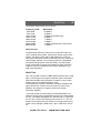
Table of Contents
Important safeguards
2
General Description
5
Front Panel Functions
6
Rear Panel Functions
11
Other Features
13
Radio Theory Primer—Frequency & Wavelength
14
The Electromagnetic Spectrum
15
Radio Propagation
15
Shortwave Broadcast Bands
17
Amateur Radio Bands
18
World Time
19
Warranty and Service
21
Specifications
22
1-800-773-7931
WWW.PALSTAR.COM
General Description
5
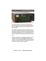
The Palstar RA30 is a compact, high-performance,
general coverage receiver for the Long Wave, Medium
Wave, and Short Wave bands, with tuning from 100
kHz to 30MHz.
The R30A HF shortwave receiver is capable of receiving multimode signals and features high sensitivity and
high dynamic range to eliminate annoying intermodulation distortion interference. Two world famous Collins
IF filters (2.5KHz ad 5.8KHz) provide unmatched selectivity.
The radio also features 100 programmable memories,
variable rate tuning and switchable bandwidth in all
modes. A 10 AA cell internal battery pack automatically
connects to the radio when the AC adaptor plug is disconnected, allowing portable operation.
1-800-773-7931
WWW.PALSTAR.COM
6
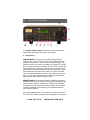
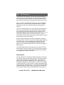
Front Panel Functions
2
3
4
10
1
5
6
9
7
8
1. On/Off & Volume Control This knob functions as the power
on/off switch and controls the audio output volume.
2. Tuning Knob
NORMAL MODE: Turning the Tuning Knob changes the frequency of the receiver. The tuning rate varies with the speed at
which the knob is turned. There are two tuning rate ranges. The
SLOW rate is 20 Hz per step, increasing to a maximum of 100 Hz
per step as the knob is turned faster. The FAST rate is 100 Hz per
step, increasing to a maximum of 500 Hz per step as the knob is
turned faster. To switch between the two rates, press the Tuning
Knob toward the front panel until it clicks. To return to the other
rate, once again press the knob until it clicks. With a bit of experience, you can easily tell which rate is selected by watching the
digital display change while turning the knob.
MEMORY MODE: Once Memory Mode is enabled (by pressing
the MEM button once), turning the Tuning Knob steps through the
stored memory channels. Pressing the Tuning Knob toward the
front panel until it clicks switches between display of the channel
numbers and display of the frequency of the stations stored in
each memory channel.
If the digital display shows “CH” {number}”, [{number} is the number of the active memory channel]; then pressing the Tuning Knob
1-800-773-7931
WWW.PALSTAR.COM
Front Panel Functions
7
toward the front panel until it clicks will cause the stored frequencies to be displayed, instead of the channel numbers. To return to
channel number display, once again press the Tuning Knob until it
clicks. To return to Normal Mode, press the MEM button again.
FREQUENCY LOCK MODE prevents the tuned frequency from
being changed by either the Tuning Knob or the UP and DOWN
buttons. This is used when it is necessary to monitor a specific
frequency, and you want to be sure the tuning cannot be changed
by inadvertently bumping the controls or by vibration. After tuning
in the desired station, to engage Frequency Lock Mode, press in
and hold the Tuning Knob for 2 seconds. The Digital Display will
show “LOCDIS” to indicate that the frequency cannot be changed.
To release the Frequency Lock, once again press in and hold the
Tuning Knob for 2 seconds. If the R30A is powered down while the
frequency is locked, it will still be locked when powered up again.
3. UP Button When in:
NORMAL MODE: Increases receiver frequency in 100 Kilohertz
steps. If the button is held down, it repeats automatically.
MEMORY MODE: Steps UP through the recorded memory channels one at a time. If the button is held down, it repeats automatically.
MEMORY STORE MODE: Steps UP through all memory channels
one at a time. If the button is held down, it repeats automatically.
4. DOWN Button When in:
NORMAL MODE: Decreases receiver frequency in 100 Kilohertz
steps. If the button is held down, it repeats automatically.
MEMORY MODE: Steps DOWN through the recorded memory
channels one at a time. If the button is held down, it repeats automatically
MEMORY STORE MODE: Steps DOWN through all memory
channels one at a time. If the button is held down, it repeats automatically.
5. MEMORY Button
a. Entering memory mode: Starting from the Normal Mode,
1-800-773-7931
WWW.PALSTAR.COM
8
Front Panel Functions
pressing the MEM button once will place the receiver in Memory
Mode, and the digital display will show memory channel information. The display will be “CH {number}”, where {number} is the
number of the active memory channel. To display the frequency of
the active
memory channel, press once on the Tuning Knob until it clicks. To
return to the channel number, press on the Tuning Knob again.
To step through the memory channels, either press the UP or
DOWN buttons or turn the Tuning Knob. If you have pressed the
Tuning Knob to display memory channel frequency, then the frequency of the stored channels will be displayed instead of the
channel numbers as you step through.
Only memory channels that have information stored in them will be
displayed. For example, if only memory channels 1 through 10
have information stored in them, continuing to step past memory
channel 10 will loop back to memory channel 1 and start over.
Likewise, if channels 1 through 10 and 15 through 20 have information stored, while channels 11 through 14 are empty, stepping
past 10 will skip over 11 through 14 and resume at 15.
To return to Normal Mode, press the MEM button again. Upon the
return to Normal Mode, the unit will be tuned to the station stored
in the memory channel selected while in Memory Mode. If the
R30A is turned off while in memory Mode, it will be in Memory
Mode when it is powered up again.
b. To store memory information: In Normal Mode, tune in the
station you wish to store in memory. All associated settings (i.e.
AM, LSB, or USB; Bandwidth; AGC; and Attenuation) will be
stored along with the frequency. Be certain that everything is correct before entering Memory Store Mode, because once Memory
Store Mode is enabled, you will not be able to view or change the
frequency or to view or change the associated settings.
c. To enter Memory Store Mode: First tune in the station you
desire to store, then press and hold the MEM button for 2 seconds. The digital display will show “CH {number}.” The default
{number} displayed will be the lowest available empty memory
channel number, and {number} will be flashing.
1-800-773-7931
WWW.PALSTAR.COM
Front Panel Functions
9
d. To store the previously tuned station in the default channel
number, press the MEM button once.
e. To store the previously tuned station in a memory channel
other than the default: First select the channel desired by using
the Tuning Knob or the UP and DOWN buttons. Empty channels
will be indicated by a FLASHING channel number. Previously
used channels will be indicated by a FLASHING channel number,
followed by the FLASHING letter “P”. Choosing to store in a previously used channel will cause the new station information to overwrite the previously stored information. Once the desired channel
number is displayed, press the MEM button once to store.
f. If you are in Memory Store Mode, and decide that you do not
want to store a memory, turn the power off and wait 5 seconds or
so. When the R30A is turned on again, it will come up in Normal
Mode.
NOTE: The memories in the Palstar R30A are non-volatile, the will
remain no matter how long power is disconnected from the receiver. Once a memory channel has had information stored to it, it
cannot be deleted or emptied, it can only be overwritten by new
information.
Digital Display
NORMAL MODE: Displays received frequency.
MEMORY MODES: Displays memory channel information.
FREQUENCY LOCK MODE: Displays “LOCDIS”
6. MODE Button - Repeatedly pressing the MODE button steps
through Amplitude Modulation (AM), Lower Side Band (LSB), and
Upper Side Band (USB) reception modes. The currently selected
mode is indicated by the lights to the left of the digital display. The
bandwidth automatically switches to the width appropriate for the
reception mode selected.
7. BW (BandWidth) Button - Switches between WIDE bandwidth
(5.8kHz) for AM reception and NARROW bandwidth (2.5 kHz) for
SSB reception. The indicator is lit when bandwidth is NARROW.
1-800-773-7931
WWW.PALSTAR.COM
10
Front Panel Functions
The bandwidth automatically switches to the width appropriate for
the reception mode selected by the MODE button, but the opposite bandwidth can be selected by pushing the BW button once.
Pressing BW again will return to the previous setting.
8. AGC (Automatic Gain Control) Button - Switches between
Fast and Slow AGC response time. The indicator is lit when AGC
responses time is FAST. For most normal reception, AGC response time should be SLOW. The primary use for the FAST response time is when listening to CW (Morse code) stations.
9. ATTenuator Button - Switches in 10 dB of attenuation to prevent overloading of the receiver by strong local stations. The indicator is lit when attenuation is ON. For most normal reception, attenuation should be OFF.
10. Headphone Jack - A standard 1/4” monaural phone plug (2
conductor) is provided to enable listening without disturbing others. The headphone jack is designed for use with 8 ohm monaural
headphones. If stereo headphones are used, the sound will only
be heard in one ear. When headphones are plugged in, the internal speaker (of external speaker, if one is in use) is disabled.
1-800-773-7931
WWW.PALSTAR.COM
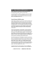
Rear Panel Functions
1
2
4
3
11
5
7
8
6
11
10
9
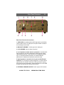
Rear Panel Functions/Connections
1. LINE AUDIO: A standard phono (RCA type) jack is provided to
connect audio to the Line Input jack of a tape recorder so that offair recordings can be made.
2. WING NUT GROUND: To earth ground or water pipe.
3. CLIP GROUND: same as wing nut ground.
4. Low impedance coaxial antenna connection. A standard SO239 connector for use with a standard PL-259 plug and coaxial
cable antenna feed line. This connector is for unbalanced antennas. To use with a balanced antenna, an external BALUN
(BALanced to Unbalanced transformer) should be used.
5. High impedance connection for long wire and Hi-Z dipole
antennas. For connecting a random length wire, or other end-fed,
unbalanced, wire antenna. Antennas of this type require a good
RF ground for best performance. Connect the antenna to the RED
terminal, and the ground to the BLACK terminal.
6. EXTERNAL SPEAKER OUTPUT: Audio output is DC isolated
1-800-773-7931
WWW.PALSTAR.COM
12
Rear Panel Functions/Connections
and balanced (use 1/4” mono jack or supplied 3.5mm adaptor)
The external speaker should have an impedance of 4 to 8 Ω, and
a minimum power handling capability of 3 Watts. When the external speaker is plugged in, the internal speaker is disabled
7. DISPLAY LIGHT SWITCH: This press-on, press-off switch allows the backlighting in the Digital Display to be turned off to conserve power when operating from batteries (recommended).
8. MUTE JACK: Ground center pin to mute receiver when using
an external transmitter. A standard phono (RCA type) jack is provided to connect a mute control line for use when the R30A is
used in conjunction with a transmitter. A relay contact closure or
other control circuit capable of pulling a +5 VDC logic line to
ground will cause the R30A to mute.
9. EXTERNAL POWER JACK: Connect to the provided wall
adaptor or other suitable 12 VDC power source. When an external
power source is plugged into the power jack, the internal battery
pack is disabled. The power plug is a standard 14mm long connector (2.1mm ID, 5.5mm OD, center positive). The limit of the
acceptable voltage range that can be connected to the power jack
is between 10.5 and 15 VDC. However, operating the R30A from
voltages in excess of 14 VDC for prolonged periods can cause
excessive heating of the built-in regulator chips.
If you choose to power the R30A from a source capable of
supplying high currents such as the battery of a car or boat,
you must protect the radio by placing an in-line fuse holder
in the power cable and use a fast blow fuse rated no more
than 1 Amp.
10. FUSE: Fuses internal battery only—use 5mm x 20mm 1A replacement.
11. IF OUT: Wideband 455KHz IF output for use with an external
synchronous detector.
1-800-773-7931
WWW.PALSTAR.COM
Other Features
13
Tilt Bail - A fold-down wire bail is provided to tilt the R30A to a
more convenient angle, as illustrated on the front cover.
Internal Battery Pack - The Palstar R30A has provision for internal battery operation. Operation from the battery pack is enabled
by the Power Source switch on the back panel. The internal battery pack uses 10 “AA” size penlight cells (not provided). Alkaline
cells are recommended for maximum battery life. If rechargeable
cells such as Nicad or NiMH are used, they must be recharged in
a separate charger. Access for installing or changing the batteries
is gained by unscrewing the 6 screws located on the sides of the
unit and removing the top cover. Next, remove the battery restraining strap by removing the screw at one end and then pivot it up
until the other end unhooks. Be sure to observe proper polarity
when installing the batteries. Once the batteries are in place, secure them with the battery restraining strap and replace its screw,
then reinstall the top cover.
1-800-773-7931
WWW.PALSTAR.COM
14
Radio Theory Primer
Radio Theory Primer - Frequency and Wavelength
Radio is a way of communicating across distances without the use
of wires by means of electromagnetic waves. These electromagnetic waves can travel through the Earth’s atmosphere, but unlike
sound waves, they are not reliant on the air to carry them. They
travel just as well (or even better) through the vacuum of space.
The most basic characteristic of any electromagnetic wave is its
frequency, which is the rate at which it rises from zero to some
positive level, and then back through zero to some negative level
and then back to zero again. One of these complete alternations is
called a cycle. The number of these cycles occurring each second
is the frequency of the electromagnetic wave. The unit of frequency, the cycle per second, is named after Heinrich Hertz, an
early radio researcher. One Hertz is equal to one cycle per second.
Closely related to the frequency of electromagnetic waves is the
characteristic known as wavelength. As a single radio wave or
cycle begins to leave an antenna, it travels outward through
space. How far does it get before one cycle is completed? It travels at the speed of light, 186,000 miles per second, or in Metric
units, 300 million (300,000,000) meters per second. If we were to
radiate a one hertz wave, the front edge of it would have traveled
300 million meters by the time the rear edge of the wave leaves
the antenna one second later. Thus, the wavelength of a one
Hertz transmission would be 300 million meters or 186,000 miles.
long!
If we were to radiate a wave with a frequency of one million Hertz,
one cycle would only take one one-millionth of a second, and the
wavelength would therefore be one one-millionth of 300 million or
300 meters. One million Hertz can be referred to as 1000 kilohertz
(KHz) or 1 megahertz (MHz). 1 MHz is located just about in the
center of the standard AM broadcast band. To calculate the wavelength of any frequency in meters, simply divide 300 by the frequency in megahertz.
With this explanation of wavelength, you can now understand what
is meant when someone talks about, say, the “80 meter band” or
the “49 meter band.” This is just another way to refer to a group of
frequencies that have been set aside for a specific purpose. For
1-800-773-7931
WWW.PALSTAR.COM
Electromagnetic Spectrum & Propagation
15
example, the 80 meter band is an amateur radio (ham) band that
runs from 3.5 MHz to 4.0 MHz. The 49 meter band is assigned to
international shortwave broadcasting and runs from 5.90 MHz to
6.20 MHz.
These meter designations for the bands are chosen to be a nice
round number from somewhere near the middle of the band. The
frequency of an 80 meter wave is 3.75 MHz, the frequency of a 49
meter wave is 6.122 MHz. Obviously, some of the wavelengths in
the band are shorter, and some are longer than the length designated by the band name.
The Electromagnetic Spectrum
Electromagnetic waves have different characteristics depending
on their frequency. The only difference between radio waves, the
microwaves that cook your food, light beams, and X-rays, is their
frequency. The Palstar R30A receives frequencies in the range of
100 kilohertz (kHz) to 30 megahertz (MHz). Frequencies in the
range of 100 kHz to 300 kHz are called Long Wave (LW). Frequencies in the range of 300 kHz to 2 MHz are called Medium
Wave (MW). Frequencies in the range of 2 MHz to 30 MHz are
called Short Wave (SW) or High Frequency (HF).
At frequencies above 30 MHz (which are higher than those received by the Palstar R30), we run into the range of Very High
Frequency (VHF) and Ultra High Frequency (UHF) and beyond.
We will discuss later what you can expect to hear on these different frequencies.
Radio Propagation
Propagation refers to the way radio waves travel through the air.
When radio waves leave an antenna, some of them travel close to
the ground. Receivers close to the antenna receive these ground
waves directly. The range of ground waves is limited. The closeness of the waves to the Earth means that the Earth absorbs
some of their energy, and farther away from the antenna, the
Earth curves downward, away from the straight-traveling waves,
and the waves pass too high overhead to be received on the
ground. To receive radio waves at longer distances, some other
mechanism is needed.
1-800-773-7931
WWW.PALSTAR.COM
16
Radio Propagation (continued)
The upper atmosphere of the Earth contains layers of electrically
charged or ionized gasses. These ionized layers are caused by
the action of light and energy from the Sun on the atmosphere.
The ionized layers act as reflectors of radio waves, causing them
to bounce back toward the Earth. By bouncing back and forth between the Earth and the ionized layers, it is possible for radio
waves to travel all the way around the world. This is called sky
wave reception.
The study of shortwave radio propagation is a scientific discipline
in itself, but, fortunately for us, it can be simplified. Because the
nature and location of the ionized layers in the atmosphere are
caused by the action of light and energy from the Sun, it is easy to
understand that the differences vary between day and night, and
between summer and winter. In the day and during summer, radio
reflective ionized layers are at higher altitude, and the maximum
frequency that the layers will reflect (called the Maximum Usable
Frequency, abbreviated MUF) is higher. At night, and more so in
the winter when the days are shorter, the reflective layers are at
lower altitudes, and the MUF is lower. Frequencies in the lower
VHF range and higher usually penetrate right through the ionized
layers and are only able to be reflected under rare conditions.
The basics of shortwave radio propagation can be summarized in
a few statements:
1. The higher frequencies are better during daytime and in the
summer months.
2. The lower frequencies are better during night time and in the
winter months.
3. Periods of high sunspot activity favor the higher frequencies,
periods of low sunspot activity favor the lower frequencies.
4. Solar flares and other disturbances on the Sun can cause geomagnetic storms that upset normal propagation for hours and days
at a time. These disturbances are more frequent during times of
high sunspot activity.
1-800-773-7931
WWW.PALSTAR.COM
What Can I Hear?
17
What I can hear on my Palstar R30A Receiver?
Long Wave (LW), 100 kHz to 300 kHz The most common inhabitants of this range of frequencies are navigation aids known as
non-directional beacons. They transmit at low power (usually 100
watts or so), and their signal consists of a two or three letter identifier repeated over and over in Morse code.
Medium Wave (MW): frequencies - range of 300kHz to 2 MHz
The lower end of this range, from 300 kHz to 540 kHz, was once
the mainstay of ship to shore communications, mostly in Morse
code. As ships have increasingly switched to high-tech satellite
communications, there is less and less activity there. Many official
agencies such as the Coast Guard have even abandoned their
round the clock monitoring of the old international distress frequency of 500 kHz. The main band of interest in this frequency
range is the Standard AM broadcast band which runs from 540
kHz to 1700 kHz. The higher power stations can be heard over
large areas at night. MW is also home to one Amateur Radio
band, the 160 meter band from 1600 kHz to 2000 kHz.
Short Wave (SW): frequencies in the range of 2 MHz-30 MHz
Shortwave Broadcasters The primary bands of interest in the
Shortwave (SW) spectrum for most listeners are undoubtedly the
international broadcast bands.
They are as follows:
Frequency in kHz
2300-2495
3200-3400
4750-5060
5960-6200
7100-7300
9500-9900
11650-12050
15100-15600
17550-17900
21450-21850
25600-26100
1-800-773-7931
Band Name
120 Meters
90 Meters
60 Meters
49 Meters
41 Meters
31 Meters
25 Meters
19 Meters
16 Meters
13 Meters
11 Meters
WWW.PALSTAR.COM
18
What Can I Hear?
Everyone is familiar with standard AM and FM stations, which
occupy a single frequency and broadcast on it every day. The
biggest difference that you will notice between these standard
broadcast stations and shortwave broadcasters is that shortwave
stations move around a lot. Because the target audiences of shortwave stations are located all over the world, shortwave broadcasters transmit on frequencies and at times chosen to have the best
chance of reaching the target audience at the correct time of day.
In addition, these frequencies are often changed with the seasons
to take advantage of the seasonal changes in propagation.
Another difference is that there is more day-to-day variability in the
reception shortwave stations. Because the stations are located so
far way, often on another continent, reception is totally dependant
on the condition of the atmosphere between the transmitter and
your receiver. There will be some days when your favorite station
will be very weak or not heard at all.
Amateur Radio Bands
The Amateur Radio (Ham) bands are occupied by ordinary people
from all over the world who have been licensed by their governments to engage in two-way radio transmissions as a hobby.
Whenever there is a natural disaster such as a tornado, hurricane,
earthquake, etc., the Ham bands are the place to listen. It is common for Ham radio to be the only communications link into or out
of a disaster area for many days after the occurrence. In fact, the
ability of Hams to provide emergency communications is one of
the primary reasons Ham radio exists.
The primary modes heard on the Ham bands are CW (Morse
Code, usually down at the lower end of each band), and voice
communications in the form of Single Sideband (SSB, there will be
more about SSB later on). There is also a smattering of other
modes: radio teletype, slow-scan TV, and other data communications methods. These signals require the use of special decoder
devices or computers with special decoding software in order to
read or view them.
1-800-773-7931
WWW.PALSTAR.COM
World Time
19
The Amateur Radio bands are as follows:
Frequency in kHz
3500-4000
7000-7300
10100-10150
14000-14350
18068-18168
21000-21450
24890-24990
28000-29700
Band Name
80 Meters
40 Meters
30 Meters (CW/Data only)
20 Meters
17 Meters
15 Meters
12 Meters (Shared with Fixed Service)
10 Meters
Other Services
The Shortwave spectrum is also home to many other radio services, including ship-to-shore, transoceanic airlines, government,
military, and others. Often called “Utility Stations” or “Utes” for
short, their transmission modes include CW, AM voice, SSB voice,
radio teletype and data. The monitoring of Utes is a specialized
and rapidly changing area of the SWL hobby. It is beyond the
scope of this guide to provide more details, but there are books,
magazine columns, newsletters, and internet webpages if you
want more information.
World Time
Let’s say you want to listen to a BBC newscast at 5pm. But, is that
5pm in London where the program originates, 5pm in Southeast
Asia where the BBC relay transmitter is located, or 5pm in New
Zealand, where the intended audience lives?
To eliminate such problems, shortwave broadcast schedules are
kept in World Time. World Time is the local time at the Prime
Meridian, zero degrees of longitude, which runs through
Greenwich, England.
In the past, World Time was known as Greenwich Mean Time,
today it is usually called Coordinated Universal Time, abbreviated
as UTC. The military designates UTC with the letter “Z” and refers
to it as “Zulu”, which is the phonetic pronouncer for “Z.” UTC is a
24 hour clock and the times are written in four digits with no punctuation. Thus, midnight is 0000 hours, 1pm is 1300 hours, and so
on.
1-800-773-7931
WWW.PALSTAR.COM
20
CW Reception
To convert UTC to local time, you will need to know how many
time zones you are located east or west of Greenwich, England. If
you are located east of Greenwich, you add the number of time
zones, west of Greenwich you subtract the number of time zones.
Also, you need to remember that UTC never goes on Daylight or
Summer Time, so your offset will be different between summer
and winter if you live in an area that sets the clocks forward in
summer.
If you live in North America, one of the easiest ways to determine
UTC is to tune your R30A to the National Institute of Standards
and Technology’s shortwave stations, WWV or WWVH, which
broadcast simultaneously on standard frequencies of 2.5, 5, 10, 15
and 20 MHz. (WWVH does not transmit on 20 MHz.) They announce the UTC time every minute, with accuracy tied to the most
accurate atomic clocks on the world.
WWV is located in Boulder, Colorado, and WWVH is located on
the Island of Kauai in Hawaii. So you can tell them apart, WWV has
a male announcer voice, and WWVH has a female announcer
voice. One or the other of these stations should be able to be
heard on one of the frequencies 24 hours a day from anywhere in
North America.
.
You may find that having a clock that can be left set to UTC will
make it easier to figure out when your favorite shortwave program
is on. There are several low-cost 24 hour digital clocks available
from suppliers who cater to radio buffs.
CW Reception
CW (an abbreviation for Continuous Wave) or Morse code reception requires a bit more doing than listening to AM voice transmissions. A CW transmission is simplicity itself -- a transmitter is
switched on and off by a telegraph key in the pattern of the dots
and dashes of the Morse code. However, if you tune in this signal
in regular AM mode, all you will hear is a kind of intermittent raspy
noise as the dots and dashes go by. To convert the CW signal into
a pleasant audio tone that is easy to read, there is a circuit in the
receiver called a Beat Frequency Oscillator (BFO). The BFO cre1-800-773-7931
WWW.PALSTAR.COM
21
Single Sideband (SSB) Reception
ates a signal that is mixed with the received signal with just
enough frequency offset to result in the audio tone.
In the Palstar R30A, the BFO is engaged by choosing the Upper
Sideband (USB) or Lower Sideband (LSB) modes. As you tune
across a CW signal, its pitch will change, and you tune until the
pitch is most pleasing to your ear.
Single Sideband (SSB) Reception
Single Sideband (SSB) is a mode that provides the benefits of reduced bandwidth (thereby taking up less room on the radio dial)
and greater efficiency in the use of transmitted power (thereby
allowing the signal to effectively reach further without increasing
transmitter power). The cost of these improvements is the requirement that the receiver have a Beat Frequency Oscillator (BFO),
and tuning is somewhat more difficult. SSB is widely used by
Hams, Utility stations, the military, and even some shortwave
broadcasters.
Here is a brief explanation of what SSB is: a radio transmitter is
tuned to the frequency it is to transmit on, called the carrier frequency. The desired signal (voice or music) is mixed with the carrier frequency in a process called modulation. The result is three
frequencies: 1) the original carrier frequency, 2) an upper sideband consisting of the carrier frequency with the modulating signal
added to it, and 3) a lower sideband consisting of the carrier frequency with the modulating signal subtracted from it.
All of the information to be transmitted is contained in each sideband. Once sidebands are generated, the only purpose the carrier
serves is to provide a reference for the receiver to use in recovering the audio from the signal. If you strip away one of the sidebands and the carrier, what is left is a Single Sideband signal.
Feed it to an antenna, and it will go out over the air just like any
other radio frequency signal. (As you can see, the term “carrier” is
a bit of a misnomer; it really doesn’t “carry” anything) Either the
upper or the lower sideband can be used.
A regular AM receiver cannot properly process an SSB signal
without the carrier to use as a reference. If you try to listen to an
1-800-773-7931
WWW.PALSTAR.COM
22
Antennas
SSB signal in AM mode, you will hear a highly distorted sound,
often described as being a "Donald Duck" type of sound. To properly hear the audio, a local replacement for the carrier is provided
by the BFO.
The "USB" and "LSB" mode buttons on the front of your Palstar
R30A are pre-tuned and optimized BFO settings for the reception
of Upper and Lower Sideband signals. You must choose the correct one: listening to USB in the LSB mode or vice-versa will result
in more distortion. To avoid confusion over which to use, Hams by
agreement use LSB on 160, 80, and 40 Meters, and USB on the
bands above that. Shortwave broadcasters tend to use USB.
Having chosen the correct USB or LSB setting, as you tune across
a SSB signal the audio pitch will change, and you will reach a
point where the voice becomes understandable, and it finally will
reach a normal sounding pitch. If you continue to tune past, the
pitch will again change.
ANTENNAS
Previously we talked about the relationship between frequency
and wavelength. Antennas work best when their length is a significant fraction (i.e. 1/4 or 1/2) of a wavelength. That means that an
antenna gives its ideal best performance on only one frequency.
Since the Palstar R30A receives from 100 kHz to 30 MHz, the
range of wavelengths it covers is from 3000 Meters to 10 Meters,
so no single antenna can give optimal performance on all frequencies.
Fortunately, receiving antennas are less demanding than transmitting antennas, and adequate performance can be had with quite
simple arrangements. If you live in an ordinary frame or brick
home, surprisingly good results can be had with a wire strung
around the walls of a room. Just strip 1/4" (10 mm) or so of the
insulation from one end and connect it to the Red terminal on the
antenna terminal block on the back of the R30A. The wire can be
simple 22 gauge insulated hookup wire. If you don't have a metal
roof, effective wire antennas can also be strung in attics.
You may desire the improved performance that an outdoor an1-800-773-7931
WWW.PALSTAR.COM
23
Antennas (continued)
tenna provides, or, if you live in a steel-reinforced or metal-sided
building, it may be too shielded for an indoor antenna to work well.
Performance of the antenna will be improved by providing an earth
connection to a ground stake. For best results, get a good quality
ground stake approved for grounding an electrical service entrance, and drive it at least 8 feet into the earth. The wire from the
ground rod connects to the wing nut or to the Black terminal on the
antenna connector block on the back of the radio. The wire used in
an outdoor antenna needs to be strong enough to support its own
weight, as well as to hold up any additional weight such as ice
from an ice storm. Normally, 14 gauge or larger is considered an
adequate size, especially if the wire is copper-clad steel especially
designed for antenna use. If the far end of the antenna is supported by a tree or other support that sways in the wind, a pulley
and weight arrangement will prevent the swaying from putting additional strain on the wire.
WARNING: Any outdoor antenna MUST be located
so that it cannot fall on power lines or power lines
cannot fall on it, if they should come down. Also,
any outdoor antenna MUST have an approved
lightning arrestor, installed in accordance with applicable building and electrical codes, at the point
where the antenna connection enters the building.
1-800-773-7931
WWW.PALSTAR.COM
24
Specifications
Frequency Coverage
100 kHz to 30 MHz
Reception Modes
AM, LSB, USB, CW
Receiver System
Microprocessor controlled PLL tuning,
dual conversion superheterodyne receiver.
Display
6-digit backlit LCD display, additional
indicators show ATT, AGC, LSB, USB,
AM, BW Analog S-meter, calibrated S1 to
S9, +20dB, +40dB, +60dB
Tuning
Rotary encoder, Tuning rate: 20 Hz to 100
Hz slow and 100 Hz to 500 Hz per step in
fast mode. Up/Down buttons: 100 KHz per
step
Memory
100 frequency memories selected with
front panel encoder tuning knob or up/
down buttons. Receiver frequency is
retained while switched off. Locked display
with tuning knob.
IF Filters
All modes, either 2.5 kHz or 5.8 kHz
operator selectable
RF Attenuator
10 dB
Controls
Power on/off and volume
MODE AM, LSB, USB
MEM
Memory button
ATT
Attenuator
BW
Bandwidth
AGC
Fast or Slow
Up & Down (100 KHz steps)
Antenna Inputs
50 Ω SO239 and
500 Ω and ground with
compression terminals
Audio Outputs
External speaker—1/4” jack selected
balanced output.
Headphone—1/4” jack
Internal Speaker is disconnected when
headphones or external speaker are
plugged in. Recorder output (line audio).
Mute audio for use with a transmitter.
Power Supply
External 12 DC supply & internal 10 cell
battery pack for portable use (lamps in off
mode). 2.1mm ID, 5.5mm OD, center
positive DC Input Jack
1-800-773-7931
WWW.PALSTAR.COM
Specifications
Dimensions
232mm W x 100mm H x 225mm D
9.13” W x 3.94” H x 8.88” D
Weight: 1.8 kg (3.9 lbs)
Sensitivity
100 kHz to 2 MHz
AM
SSB
2 MHz to 30 MHz
AM
SSB
25
2 µV
.5 µV
1 µV
.5 µV max
10db(S+N/N)
Selectivity
45 MHz
455 Khz (AM)
SSB
Dynamic Range
>90 dB at 50 kHz from desired
Spurious Responses
At 45 MHz
At 455 MHz
Intermodulation
Third order Intercept +15dbm
Frequency Stability
+/- 20 Hz per hour –15°C to +50°C
AGC Range
1µV to 500 mV
Attack time
Delay - slow
Delay - fast
Audio
2 watts into 8 Ω
2% THD
Distortion:
1 kHz signal AM at
60% mod. Depth
< 1%
SSB
< .5%
S/N Ratio
(AM Mode)
6 kHz filter ref. 60% @ 1 kHz
5 µV
20 dB
500 µV
> 50 dB
(SSB Mode)
5 µV
30 dB
500 µV
> 50 dB
Power Supply
DC required
12 vdc@1A regulated
Quiescent current 350 mA (with lamps)
Typical current use 350-800 mA
1-800-773-7931
8 kHz BW
6 kHz
2.4 kHz
> 65 dB rejection
> 90 dB rejection
< 2 dB change
< 3 ms
< 4 secs
<.5 secs
WWW.PALSTAR.COM
26
Notes
1-800-773-7931
WWW.PALSTAR.COM
Warranty and Service
27
Limited Warranty
Repair Policy
Palstar Inc. warrants products manufactured by it to be free from defects
in material and workmanship under
normal use and service for a period
of two (2) years for the ATAUTO, AT10K, AT5K, AT4K, and
all other products for one (1) year
from the date of delivery to the
first buyer (the “Warranty Period”).
Palstar Inc’s obligation under this warranty is limited to repair or replacement of the product; at its option at
the Palstar factory in Piqua, OH.
When sending in a product for service,
please “double” box it carefully and
ship it insured for your protection.
Please include a note clearly describing
the problem, how you wish the item
returned and how you wish to pay for
the service. Package your radio properly. Palstar, Inc. is not responsible for
merchandise damaged in shipment.
Our service rate is $30 per hour (1/2
hr. minimum).
Return Policy
All returns must receive prior authorization from Palstar. Returned items
must be received in original—AS
Effective only when the product is
returned to the factory with all trans- SHIPPED– condition including the
original box, manuals, accessories, and
portation charges prepaid and examination of the product discloses in Pal- copy of sales receipt. Returns must be
star’s judgment, to have been defective within 14 days of purchase. Returned
items are subject to a 25% restocking
during the Warranty Period.
fee. Shipping is not refundable.
The Warranty Period shall not extend
beyond its original term with respect
to interim in-warranty repairs by Palstar. This Warranty Period shall not
apply to any product which has been
repaired or altered by anyone other
than Palstar without prior written
authorization. Warranty does not extend to any products which have been
subject to damage from improper installation, application or maintenance in
accordance with the operating specification. Palstar neither assumes nor
authorizes any person to assume for it
any obligation or liability other than
herein stated.
1-800-773-7931
WWW.PALSTAR.COM
Palstar Incorporated
9676 N. Looney Rd.,
Piqua, OH 45356 USA
Customer Service and Sales Telephone:
1-800-773-7931
Fax:
1-937-773-8003
Email:
[email protected]
Version 1.1 August 15, 2008