1
WIDEBANDRECEIVER
rn
^
z
l-r-7
H l
t t -
¿
I I
t
¡
INSTRUCTION
MANUAL
KENWOODCORPORATION
U
O
U
i
M, wXT)
OpRTNTEDtN JApANB5o-8196-10(K,
88/12111098765432
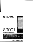
Thankyou for purchasingthis new receiver.
IMPORTANT:
Pleasereadthis instructionmanualcarefullybeforeplacing
your receiverin service.
MA N U A L .
SA V ET H I SI N ST R U C T ION
The followingexplicitdefinitionsapply in this manual:
only, no risk of
: lf disregarded,inconvenience
Note
equipmentdamageor personalinjury.
Caution : Equipment damage may occur, but not personalinjury.
c0tITEilTS
1.
2.
3.
4.
B E F O RO
EP E R A T T O N
. . . . . . . . . . . . . . . . .4. . .
5.
............
6
ANDAccEssoRlEs
spEctFtcATroNs
T N S T A L L A T | O|NN S T R U C T I O N S . . . . . . . . . . . . . . . . .7.
. . . . . . . . . . . . . .1. 1
oPERAT|ON
CONTROLS
OPERATING
................15
R E C E T VO
EP
RE R A T T O N .
Reception
FrequencySelection
.........17
M O D ES e l e c t i o n . . . . . . . . . . . . .
............18
MEMORY.....
MicroprocessorMemory Back-up
6.
7.
8.
M i c r o p r o c e s sI n
o irt i a | i 2 a t i o n . . . . . . . . . . . . . . . . 1. .9. . . . . . .
MemoryChannel
MemoryContents
'
Memory Entry
...............2O
M e m o r yR e c a .l .l . . . . . . .
Band
Programmable
...............22
M e m o r yS h i f t . . . . . . . . . . .
SCAN
ScanOption
Condition
Hold/Resume
...............23
A l lB a n dS c a n. . . . . . . . . .
BandScan
Programmable
MemorC
y h a n n eSlc a n . . . . . . . . . . . . . . . . . . . . . . . . . . . . 2 4
MemoryChannelGroupScan
MemoryChannelLockout
...............25
M E S S A GM
EE M O R Y . . . . .
MessageEntry
M e s s a gM
e e m o r yR e c a | | . . . . . .......... . . . . . . . . . . . . . . . 2 7
.................29
MA|NTENANCE...........
Service
....................30
I n C a s eo f D i f f i c u l t y . .
anothersheet
SCHEMATIC DIAGRAM..
o p i l o N A L A C C E S S O R | E .S. . . . . . . . . . . . . . . . . . . . . . . .3. 1. . . .
................32
REFERENCE
1. BEFORE
OPERATIOIII
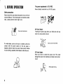
Safety precautions
Neverremovethe case unlessinstructedto do so in this lnstruction Manual. lf the internalparts are touched accidentally, a seriouselectric shock might occur.
Never touch internal oarts.
The power requirementis 13.8 VDC.
Neverattemptconnect¡on
to a 24 VDCsource.
wls
DG Power Supply:
Touchingthe power plug when your hands are wet
result in a seriouselectric shock.
b.-u
gqi.
lf a metal object. such as a hair pin or a needle.comes into
contact with the power socket on the rear panel, a
dangerouselectric shock may result. Never perm¡tch¡ldren
to put anything, especiallymetal objects. insidethis unit.
Fhi-
Nevertouch with wet hands.
DC Power Supply:
Never pull, bend or extend the power cord. This could
damagethe power cord, resultingin a brokencord or shortcircuit.
Always graspthe plug.
Installationnotes
to direct
that ¡sexposed
Do not placethisunitin a location
neara heatingappliance,
etc.
sunlight,
To maintain good ventilation, do not put books or papers
on the unit.
Choosea locationthat is relativelvfree from vibration.
Do not store or use the unit in a dusty locationor in a moist
atmosphere.Select a location where there is good ventilation.
ln case of an abnormal odol
turn
lf an abnormalodor or smokeis detected,immediately
the power OFF and pull out the power cord. Contactyour
dealeror nearestServiceStation.
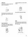
Cleaning
Do not use volatile solvents such as alcohol,paint thinner,
gasoline,benzine,etc. to cleanthe cabinet.Use a silicone
cloth or a clean dry cloth.
c
M
Silicone cloth
Thinner Benzine
2. SPEG|F|CAT|0ilS
AilDACCESSoRTES
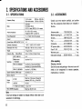
2-1. SPEC|F|CATTONS
U . S . A .v e r s ¡ o n
: 500 kHz-824 MHz
Othermarketversion : 5OOkHz- 905 MHz
A3E (AM)
F 3 E ( F M - N ,F M - W )
C 3 F ( T . V v i s u a l ,N T S C )( U . S . A .v e r s i o n l
FrequencyRange
Mode
Power Reou¡rement
50-3OOO(5OOnominal).
Unbalanced(ANT 1 and ANT 2)
l1 - l6 VDC (13.8 VDCnom¡nal)
Ground
Negative
CurrentDrain:AUDIOOUTPUT(1 W)
1 A
OperatingTemperature
- lOoC- +600C (l40F- l40oF)
Antenna lmDedance
D i m e n s i o n{ W
s xHxD}
l S O x 5 0 x 1 7 6m m ( 7 . O ' x 2 " x 6 . 9 " 1
Weight
1 . 5 k s ( 3 . 3l b s )
Frequency Step
Sensitivity
Manual Mode
5rV
Medium-wave
broadcasts
F M . N( 1 2 d B S I N A D )
Lessthan 10 pV
FM-W 112dB SINAD}
SquelchSens¡tivity{FM-Nmode)
Memorv Channel
Output
Power
5 kHz, 12.5 kHz, 20 kHz, 25 k{z
A M ( 1 Od B S / N )
Lessthan 6 pV (lessthan 60 MHz)
Lessthan 3 pV (morethan 60 MHz)
Lessthan 1 ¡V (83 MHz)
Lessthan 0.1 pV
loo
EXT.SP
More than 2 W (across8 O load 5%
distort¡on,FM 1 kHz, +3 kHz DEV)
LINEOUT
150 mV
T.V visual(U.S.Aversion) 1 V p - p , 7 5O
FM-W STEREOSeparation
More than 3O dB 11 kHz)
Note:
Circuit and ratings are subject to change without not¡cedue to advancementin technology.
2-2. ACCESSORIES
Unpackyour new receivercarefully,and conf¡rm
that the accessorieslisted below are included in
the box.
. .5. . . . .1. e a .
A n t e n n ac a b l e. . . . . . . . . . . . T 9 0 - O 3 6 2.-.O
M o b i l em o u n t i n gk i t . . . . . J 21 - 3 4 3 7- O 4. . . . . . . . . . 2e a .
. . s. .e. t
Screws................N
. . .9.9. .- O 3 2 2 - O 5 . . . . . 1
a.
F o o t. . . . . . . . . . . . . . . . . . . . . . . . . J O 2--OO54.4. .1. . . . . .e. 4
C o n n e c t o r . . . . . . . . . . .E. .3.1.-.3. .3 6 6 - 0 5. . . . . . . .1. .e a .
. . .5. . .1. e a .
D Cp o w e rc a b l e . . . . . . . . . . . E 3 O - 2 0 5 .3. -. O
F u s e( 1 . 5 A ) . . . . . . . . . . . . . . . . F 5
O2s1--1O 5. . . . . . . .1. .e a .
. . . . . . . . . .1. e. a .
W a r r a n tcya r d. . . . . . . . . . . .
I n s t r u c t i omna n u a l . . . . . . . 8 5 0 -9861- X X . . . . . . . c1o p y
After unpacking
Shippingcontainer:
Savethe boxes and packing¡n the event your unit
needs to be transported for remote operation,
or service.
maintenance.
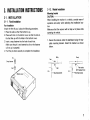
3-1-2. Mobile lnstallation
lll|sTRucTl0tl|s
3. ilrtsTAltATlotl|
Mounting bracket
3.1. INSTALLATION
3-1-1. Fixed Installation
Foot installation
Attach the feet (4 pcs.) usingthe followingprocedures.
1. Placethe radioso that the bottom is up.
2. Placeeach foot on the bottom cover so that the hole in
the feet line up with the holesin the bottom cover.
3. Inserta snapfastenerinto the hole of eachfoot.
(Make sure the pin is not insertedtoo far or the fastener
will not go in properly.)
4. Pushthe pin down securelyto completethe installat¡on.
Pin
Snap fastener
GAUTION:
When installingthe receiverin a vehicle,considereaseof
operation and safety when selectingthe installationlocation.
Make sure that the receiverwill not slip out of place while
operatingthe vehicle.
1. Securethe receiverunderthe dashboardusingthe supplied mounting bracket. Install the bracket as shown
below.
Body
3-2. CONNECTIONS
3-2-1. Precautions
the power connec1. Beforeconnectingor disconnecting
of the
tor, be sure to turn off the power switches
power
supply'
receiver,enginekey, and the DC
2. Observethe polarity of the cable' The receiveroperates
polarity muit
on 13.8 VDC, negativeground' Battery
be correct. The power cable is color coded:
+ (Positive)Polarity
Red
- (Negative)PolaritY
Black
Notes:
removethe
1. Before installingthe power cable, be sureto
safety'
for
negativelead from the battery
check for
2. Afier installationand wiring, be sureto double
negative
the
reconnecting
before
correct installation
lead to the battery terminal'
for
3. lf the fuse opens, be sure to check each conductor
damage.
that
After-you have checked the cable and determined
of the
one
with
FUSE
the
replace
problem
no
is
there
same rat¡ng.
holder with
4. After completingthe wiring, wrap the fuse
moisture'
tape to Protect aga¡nst
is too
5. Do not remove the fuse even if the power cable
long.
Antenna
(A) Antenna
grounding
The ¡nstallationof the antennaand a good earth
broadis important for optimum reception of short-wave'
will
antenna
good
outdoor
"u", o, amateurradiosignals'A
providethe best results.
as high as
Á simple method is to install the wire antenna
for good
length
full
its
to
extended
be
must
it
possible,
results.
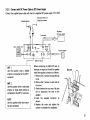
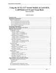
3-2-3. Connect w¡th DC Power Cableto DC Power Supply
powercablewith fuseto a regulated
DCpowersupply(13.8VDC)'
Connect
the supplied
Supplied antenna
Wide band antennaor
I
I Singleband antenna
Fus€ holder
Regulated
DC power supply
r--l
-+l
U.S.A. versiononly
fi ",""0t
+@d
I
External sDeaker
@ @
LINEOUT jack
ANT 1
Use this position when a Mobile
antennais connectedto the ANT 1
connector.
ANT 2
Use this positionwhen a wide band
antenna or single band antenna is
connectedto the ANT 2 connector.
AUTO
Use this position when both antennas are connected.
I
Beforeconnectingthe LINEOUT jack, to
¡nterruptany signalto the built-¡nspeaker
installthe suppliedconnectoras follows.
1. Removethe 3 screwssecuringthe top
cover.
2. Removethe 2 screws on each side of
the cover.
3. Gently removethe top cover. Be sure
not to disconnect the wire to the
speaker.
4. Insert the supplied connector as
shown.
5. Replace the cover and tighten the
screws to completethe installation.
3-2-4. Mobile
A. BatterY connect¡on
to the
Connecttñe suppliedpower cable w¡th fuse directly
lighter
cigarette
the
to
Connecting
Uattery terminals'
socketcancauseapoorconnection,andexcessivevoltage
drop, and lead to Poor Performance'
Mobile antenna
f ll
B. lgnition noise
ignition noise;
This- receiver is designed to suppress
however,ifexcessivenoiseispresent'¡tmaybenecessary
or an exterto use suppressorspark plugs (with resistors)'
regarinformation
for
your
dealer
nal noise filter' Contact
dingthese devices.
( - ) lead polarity ¡s correcl
Make sure the pos¡tive ( + ) and negative
antenna or
i Wide band
I Single band antenna
i
when wiring to the battery'
Enginecompartment -afu_-
*
l"d
t f ñ
Passengercompartmenl
LlJ
I
To the
Supplied DC Power cable
"[| ["
Fuse
feceiver
w
v
n
t
Chass¡sor
fire wall
@ @
ANT 1
is conUse this position when a Mobile antenna
nected to the ANT 1 connector'
ANT 2
single
Use this positionwhen a wide band antenna9r
connector'
2
band antennais connectedto the ANT
AUTO
Úse ttr¡s positionwhen both antennasare connected'
t0
I
is too small' d¡sassemble the
lf the hole in the fire wall or chassis
the hole'
through
wire
the
thread
to
holder
fuse
From Passengel
F
compartment
Thread like thls.
4. OPERATIOil
4 - 1 . Operating
Controls
EEEEIEEIEE
e
@
VOL control/POWERsw¡tch
The volume control and power switch are combined.
Rotating the control clockwise will turn ON the
receiver.
Advancing the control further clockwise will increase
the volume.
SOL control
The SOL control is used to eliminatenoise in the FM-N
mode during no signalperiods.Normallythis control is
adjustedclockwise until the noisejust disappears,and
t h e B U S Yi n d i c a t o r( S I G N A L r r - r ¡ - r i - r ) g o e s o f f .
This point is commonly know as the SquelchThreshold
point. For scan operat¡onsthis control must be set to
the threshold point. When an incomingsignalis weak
or unstable, readjust the SOL control for optimum
reception.
@
PHONEjack
Output terminal for earphone.The built-in speaker is
disabledwhen the earphonejack is insertedinto this
jack. Use a subminiature
plug.
@
VFO/M.ch (Memory channellkey
This key is used to switch between the VFO and
Memory channelmodes.
@
SGAN Key
This key is used to start and stop scanning.
@
MSG Key
This key is used to enter or recalla message.
ll
o
@
Tuning contro¡
This control is used to select the desiredreceive frequency, Memory channel. Scan direction' and
MESSAGEcharactor'
O t'looe rey
This keY is used to selectthe MODE'
@ rt¡ rey
in VFO mode:
UP/DWN keYs
These keys are used to step increaseor decreasethe
desired receive frequency, Memory channel' Scan
direction,and MESSAGEdigit.
@ Numer¡c keys
in VFO mode:
in M.ch mode:
in MESSAGE
entry moder
@ sreer"v
in VFO mode:
in M.ch mode:
Press the ENTERkey and then
these keYSto enter a frequencY
directly.
Pressthese keYsto recalla Programmableband.
Press these keYs and then the
ENTERkeY to enter a MemorY
channeldirectlY.
Pressthese keYs(1 - 7) to enter
a symbol.
This key is used to select the
Frequencystep.
Pressing the keY during the
AUTO mode will release the
AUTO mode function.
This key is used to sPecifYor
releasethe Memory Channelto
be locked out dur¡ngscan operations.
in M.ch mode:
This key is used to enter a frequencyinto a MemorYchannel'
This key is used to transfer a
Memory channel frequency into
VFO mode. (MEMORYSHIFT)
@
C key
This iey is used to releaseSCAN, and Memory Entry'
and to clear a frequency selectionor Memory channel
selectionwhen us¡ngthe numerickeys'
@
S. SELkeY
This key is used to selectthe desiredSCAN mode'
@
BEEPkey
This key is used to turn the Audio confirmationtones
ON and OFF.
@ erurentey
in VFO mode:
in M.ch mode:
This keY is used to beg¡n the
direct keYboard inPut of the
operating frequencY using the
numerickeys'
This keY is used to directlYinPut
the Memory channelnumberusing the numerickeYs.
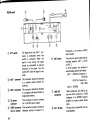
LGD display
@ MESSAGE
ñirl tlul h-ul ,-\ul
,AI 'A(.'AI 'AI
On after pressingthe
MSG key and when a
messageis displayed.
- I I I I I - I I I I I I
MODE - AIII IM.I{ FM.W
srEP - 5k r2.5k zok zsk
] nuro STEBEO
O MHz
SCAN - SEEI(CARITITE AUOIO
6É-lE t¿>t\ñ tJ\\lF
On whenevera receive
frequencyis displayed.
@ Frequencydisplay
Displaysthe receive frequency, and
Memory Message.
@ slctal
?--:rrrrr¡rrr
This level meter indicatesthe relative
BUSy
I
input signalstrength.
¡nd¡catorI
I
On whenever the squelchis open in
the FM-N mode.
@$g="rt:
#,igil,[f-%* ] ruro
Displaysthe selectedMODEand FrequencySTEP.
@ scan - sEEr(cABrTr¡rEAuDro
Displays the selected Scan-Resume
condition.BlinksON and OFF when
the scan function has been selected.
O lsTEREol
BlinksON and OFFduringMemoryEntry.
@ Symbol:
ON when recievingFM radio broadcasts.
t3
REARpanel
The signal level from ANT 1 connector is attenuated when this
switch is activated. When the
signal is very strong, the signal
should be attenuated to Prevent
distortion of the signal. Turn the
sw¡tch OFF when the signalis verY
weak.
should be attached
@ Aruf I connector This connector
to a suitable mobile antenna for
@ nff
switch
@ nruf switch
receiving.
should be attached
@ anr 2 connector This connector
or
@
o
t4
to a suitablemulti-bandantenna
singleband antenna.
This connector is used to connect
DC power
the 13.8 VDC PowersuPPlY.
connectof
VIDEO connector This connectoris usedto connect a
(U.S.A. version) television monitor to receive T'V.
@ LINEour
connectols
@ exr. sPiack
broadcasts,or to connect a VIDEO
tape recorder.
This switch is usedto selectthe appropriateantenna,ANT 1' AUTO
or ANT 2.
In AUTO Pos¡t¡on.the antenna ¡s
automaticallyselectedas follows:
ANT 1: AM 500<frequency<
1630 kHz
<
<
frequencY
5
87.
FM
1 O 8 . 1M H z
ANT 2: OTHERS
These connectors are used to attach the AUX connector or TUNE
connector of a STEREOreceiver/
amplifire to receive stereo broadcasts.
This jack is for connectionof an external sPeaker.
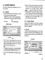
4-2. RECEIVER
OPERATION
The Receiverwill supply audio confirmationwhen a function is activated.
4-2-1. Reception
1. Connectthe power supply and the antennas,and then
set the switches and controls as follows:
POWER(VOL)control: OFF (Fullycounterclockwise)
POWERswitch of the DC power supply(FixedStation)
: OFF
SOL control
: Fully counterclockwise
POWER(VOL) control
EIE¡T=IEElElEIEE@
2. Turn ON the DC power supply and then turn the
receiver's power switch ON. After a few second the
display panel will indicateas shown in Fig. I and some
control's and key's lights will turn on.
Note:
lf the displayis not as shown Fig. 1 resetthe microprocessor using the procedurein Sectk¡n¿l-3-2 page 1g - 19.
4. Rotate the Tuning control and select an open channel.
Then turn the SOL control clockwise until the noise
disappears and the BUSY indicator (SIGNAL
-!::::ri:i
) goes OFF (Thresholdpoint).(FM-Nonly)
5. Select the desiredfrequency when a signal is received.
the BUSYindicatorwill turn ON and S-meterwill deflect.
6. To turn off the receiver,turn off the receiver'sPOWER
switch before you turn off the power supply, or if in a
vehicle,before you stop the engine.
4-2-2. Frequency Selection
Frequencycan be changedin the VFO mode. The selected
frequenciescan be stored in the Memory channels. (See
MemoryEntry page 19.)
A. VFO mode
To select the desiredoperatingfrequencyin the VFO mode
rotate the Tuning control, pressthe UP/DWNkeys, or enter
the desiredfrequencydirectly by using the ENTERkey and
numerickeys.
i.i
E=
E
E
EIE]EEEEIEE
3. Turn the VOL control clockwise until a signalor noise is
heard.
t5
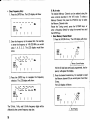
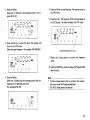
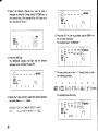
Direct Frequency EntrY
1. Pressthe ENTERkey. The LCD displaywill show
.
SIGI{AL
toDESTEP - 5¡
scAx - sftÍ
.
M
t
r
H
z
ftw
rt
r
t
t
t
l
l
2. Enterthe frequencyto the nearestkHz. For example
to enter the frequencVof 145.220 MHz you would
press 1, 4, 5, 2, 2. The LCD display would then
show:
I t l t |
| -l.tSIGNAL
rooE-STEP 5¡
scaÍ - srrx
rl
- l
- f
,-
MHz
.
l
r
l
t
l
l
l
lf M.ch OOhad been previouslyprogrammed,the frequency will appearthe disPlaY.
l
selection.The LCD displaywill show:
I tJ t-_ _:r :!
I _1. t_
SIG'{AL
TOD€ STEP - 5T
scall - srx
l
,_
,-t ,-l
l_1. l-l
l{thz
FFW
t
r
l
l
The 1O kHz, 1kHz, and O.5 kHz frequencydigits will be
affected by the current frequencystep size.
t6
SlGilAL
rODESTEPscAt{ - sErÍ
II
rr'w
3 . Press the ENTER key to complete the Frequency
I
B. M.ch mode
The desired Memory Channel can be selected using the
same controls described in the VFO mode. To select a
Memory Channel,f¡rst press the VFO/M.ch key to select
the MemoryChannelmode.
Rotate the Tuning control, press the UP/DWN keys. or
enter a frequency directly by using the numeric keys and
the ENTERkey.
o Direct Memory Channel Recall
1. Pressthe VFO/M.chkey. The LCD displaywill show:
2. Pressthe desirednumeric key. For exampleto recall
the Memory channel35 you would press 3 and then
5 keys.
The LCD displaywill show:
3. Pressthe ENTERkey to completethe Memory Channel recall.The LCD displaywill show:
MHz
.
a
SIGilAL
rooE STEP scal{ - sf¡(
t
t
1\
l
U.S.Aversion
Symbol
AM
oo1.630
AM
I 1 Ok H z
:
lo:l
087.500
(
{
087.495
5 kHz
087.500
I
108.O50
AM
AM
¡9kHz
FM.W
5 kHz
50 kHz
108.100
I
905.OOO
FM.N
, VFO STEP
108.OOO
FM-W
FM.N
1OO kHz
,
10 8 . 10 0
I
824.OOO
;
lo:l
2 VFO STEP
,
;
,
lo3l
i
lo:l
Other market
Frequency
Range
MODE
F. STEP
Symbol
ooo.500
I
001.620
001.630
I
087.495
I
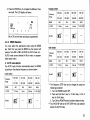
A. AUTO mode selection
The AUTO mode function automaticallyselect the MODE
accordingto the selectedfrequencyas shown below.
Symbol
a
oo1.629
F. STEP
4-2-3. MODE Selection
You must select the appropriatemode using the MODE
key. Eachtime you pressthe MODE key the receiverwill
advancefrom AM to FM-Nto FM-W to AUTO mode,etc.
(AUTO mode cannot selected in M.ch mode, or programmableband mode.)
F. STEP
ooo.s04
MODE
(M.ch 35 had not beenpreviouslyprogrammed.)
MODE
Frequency
Range
t.cr
t
Frequency
Range
European
version
ooo.504
I
oo1.629
AM
r9kHz
6-
oo1.630
087.500
I
(
087.495
108.O00
AM
FM-W
5 kHz
1 O 0k H z
,
10 8 . 10 0
I
905.000
FM-N
, VFO STEP
l
lO:l
*r The FrequencySTEPsize can be changedby using the
following procedure.
1. Turn the POWERswitch OFF.
2. Pressand hold the O key for lOkHz step, orthe 9
key for 9 kHz step.
3. Turn ON the POWERsw¡tch and then releasethe key.
*2 The VFO STEPwill be the VFO STEPthat was selected
beforethe AUTO mode.
l7
7-
B. MANUAL mode select¡on
The MANUAL mode function allows you to set the desired
frequencyMODEand STEP.
STEPsize selection
The FrequencySTEP size can be changed in MANUAL
mode. lf in the AUTO mode, the mode will be released'
Eachtime you pressthe STEPkey the receiverwill advance
from 5 k to 12.5 k to 2O k to 25 k step.
4-3. MEMORY
4-3-1. Microprocessor memory back-up
A lithium battery is contained in the receiver to retain
the
memory.Turningoff the POWERswitch, disconnecting
power cable, or a power failure will not erasethe memory'
The battery should last for approximatelyten years' When
the battery discharges,an erroneousdisplaymay appearin
the display.
Lithium battery replacementshould be performed by an
authorizéd KENWOOD service facility; either your KENWOOD dealer, or the factory, since this un¡t contains
CMOStype circuitrY.
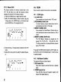
4-3-2. Microprocessor In¡t¡al¡zat¡on
¡ lnitial state of the microprocessorfrom the factory'
tt ,- Af , I t-l ,-l 7lm¡sslcr
t u ,/u ,-l ,-l lt
,-r t
-rrr
^'ol'i¡Eo :
EE
$i'iri.i[;I]il4l,huo,o'
SlGl{AL
Í.cH
6-l @ l1.--l:ñ 1J\ | s-'
After a few second
t-l ,'l t-l
l-l l-t.l-l tttnz
,'l ,-l ,t.L1
SIGI{AL
ltooE STEP scaN - srrf
II
t8
tt-w
251
t
l
l
l
. Microprocessorlnitialization
When you want to erase all programmeddata, or if the
displayshouldshow erroneousinformation,you shouldinitialize (reset) the microprocessorusing the following procedure.
There are two methodsfor resettingthe microprocessor.
A. Rest all user programmeddata except the contents of
the MemoryChannels.
1. Turn the POWERswitch OFF.
2. Press and hold the ENTERkey and turn on the
POWERswitch.
3. Releasethe ENTERkey.
B. Reset all user programmeddata includingthe contents
of the Memory Channels.
1. Turn the POWERswitch OFF.
2. Pressand hold the M key and UP (^) key and turn
on the POWERswitch.
3. Releasethe M key and UP (^) key.
4-3-3. Memory Channel
This receiverprovides10O MemoryChannels(00-99).
In addition to serving as normal memory channelsome of
the memory channelsare used to specify other parameters.
The functions of these Memory Channels are discribed
below.
* M e m o r yC h a n n e 1l 0 , 2 0 , 3 0 . 4 0 . 5 0 , 6 0 . 7 0 , 8 0 , 9 0 ,
and OOare used to store the limit for the Programmable
Band and ProgrammableBand Scan function.
* M e m o r yC h a n n e 1
l 9,29,39, 49, 59, 69, 79, 89, 99,
09 are used to store the limit for the Programmable
Band and ProgrammableBand Scan function.
4-3-4. Memory Contents
Each Memory Channelis capableof storing the frequency,
m o d e ,s y m b o l ( [ l ,
@ , . . . . . ) , a n d m e s s a g e(. R e f e rt o
MessageMemorypage 25.)
4-3-5. MemoryEntry
Memory Entry must be begun in the VFO mode.
1. Pressthe VFO/M.chkey to selectthe VFO mode.
Select the desiredfrequency using the Tuning control,
UP/DWNkey, or the numerickeys and the ENTERkey.
Selectthe appropr¡ateMODE.
(Forexample145.220 MHz, AUTO model
I tJ
I
|
t-_ _:l _:l ,-t ,-l
_1. t_
,_
l_1. t_l
MHz
SIGIIAL
t''*
$it8"- u*
scat{- srrx
t
I auro
t
t
t
l
2. Press the M key. The last Memory channel that was
previouslyrecalledwill appear and the channelnumber
will flash.
(ForexampleM.ch O0 : empty)
'
SIGIIAL
TOOE sf€P - 5r
scat{ - $rf
l
-
., ,THt
-
r-rr-l
--'J'-t
l
t
l
:
l'|'
19
3. Select the desired Memory Channel using the Tuning
control,UP/DWNkey, or the numerickeys.
(ForexampleM.ch 40;
Pressthe 4 key, and then the O key.)
.
.
slc¡lL
Íoo€ -sTEp- 5r
scat{ s¡¡¡
I
I
I
l ' r t
I
I
.MHz
\ l /
-r
r
- ' - i , t -|l - -
4. Pressthe M key again.The Memory channelnumberwill
turn OFF.The receiverwill returnto VFO mode.
t tJ
I
|
-:f ,-t t-t
t-_ :l
_l . l_
,_
l_1. l_l
?{thz
SIGI¡AL
t''t
!it&t-- '*
scax sttx
¡
I auro
t
t
r
l
5. Pressthe VFO/M.ch key to confirm the enteredMemory
contents.
I LJ L-- :J :J ,-t ,-t
|
|
S|GNAL
Ír-r
toD€srEp scAx - srrx
l
20
_(.
,_
t_
l-1. l-l
?{t}l¿
r.cf
t-l
-l ,-t
,-1
t
l
l
l
4-3-6. Memory Recall
Pleasereferto "FrequencySelectionB. M.ch mode" page
16.
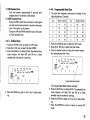
4-3-7. Programmable Band
The ProgrammableBand function allows you to define the
frequencyrange.The rangeis determinedby the frequency
in MemoryChannel-O
and -9 as follows.
The correspondingnumeric key can be used to directly
recall the frequency in Memory Channel-O.The programmableBandindicatoris the * without the MemoryChannel
number.
Kev
Memory Channel
Key
Memory Channel
10
19
6
60
20
29
7
70
79
J
30
39
8
80
89
4
40
49
9
5
qn
59
1
69
90
99
oo
o9
For example
1. Pressthe VFO/M.chkey to selectthe VFO mode.
Selectthe lower frequency,and the desiredMODE.
(Forexample145.220 MHz, AUTO mode)
-l
f:
I -i
t I tt
-.
-l
f:
t-l t-l
t-t. t-t ?¡Hz
SIGI{AL
t''t
Sroro"t,*
scaN- srrÍ
t
I ^wo
t
l
t
t
2 . Pressthe M key.
Select the -0 desiredlow end storage location. (For exampleM.ch 40)
-l
I t--l
lt|
-.
t
SlGl{AL
ioD€Ír¡
srEP-s¡
scAx-sttf
|
-f
|
r-lr-l
t-1. t-l t¡Hz
t
|
¡ | /
\"-./
-r-lll¿ ít-l u
|
l'r.
3. Press the M key to enter the data. The receiver will
return to the VFO mode.
Selectthe upperfrequency.(Forexample146.0OOMHz)
I tJ
SIG}'AL
!rto"t-,,
scAt{
t-_ ,-t ,-l ,-l ,-l
I t_l. r_l tJ
I
t"
l_1.l_l
MHz
6. Pressthe 4 key. The frequencyof M.ch 40 will appearin
the LCD display.The radiowill selectthe VFO mode.
I tJ
(
t-- _:f _:l ,-t ,-t
I _l.t_
,_
,_l.t_l
SIGi{AL
roD€fx,r
STEP- 5T
scAr - str(
t
t
t
t
l
7. Rotate the Tuning control to confirm the frequency
range.
I ^uro
srrx
t
t
t
t
8. Pressthe ENTERkey twice to releasethe Programmable
Band function.
l
4. Pressthe M key.
Selectthe -9 desiredhigh end storagelocationthat correspondsto the selectedlower limit.
(ForexampleM.ch 491
SIG¡IAL
fÍoDEsrEP - 5r
scAl{-st€x
|
t
5. Pressthe M key to enter the data. The receiverreturnto
the VFO mode.
.
|
t
.
I
t
I
t
Note:
* lf either storage location has no contents, the numeric
key cannot recallthe ProgrammableBand.
* The AUTO mode cannot be selected.
.ilH¿
\ I /
\
. -./
- '-t '-l u 1-t,
t / | \
l
21
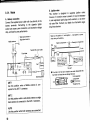
4-3-8. Memory Shift
This feature transfers the memory channel data to the
VFO. This will allow you to alter the frequency without
changingthe contents fo the memory channel.
1. Pressthe VFO/M.chkey to selectthe M.ch mode.
2. Select the desired Memory Channel number using the
Tuning control, the UP/DWN keys, or the numerickeys
and the ENTERkey. (ForexampleM.ch 40)
I tJ
I
t-- _:l _:f ,-t ,-l
I _(.
t_
l_1. t_l
,_
stct{aL
Fr-t
ÍooEsfEP - 5r
scAt{-srff
l
?tHz
f.ci
,-, ,-l
1r-l
t
t
t
l
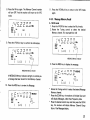
4-4. SCAN
Scan is used to samplethe band activity automatically.
4-4-1. SCAN Option
1. ALL BAND SCAN
Scan proceedsover the entire band. (VFO mode)
2. PROGRAMMABLE
BAND SCAN
The Scan frequency range is determinedby the Programmablebandfunction.(VFOmode)
3. MEMORYCHANNELSCAN
Scan proceedsthru those Memory Channelsthat actually have data and have not been lockedout. (M.ch
mode)
4. MEMORYCHANNELGROUPSCAN
The 10O Memory Channelsare devided into 10
g r o u p s{ 1 Ot o 1 9 , 2 0 t o 2 9 , . . . . 9 0 t o 9 9 , 0 O t o O 9 } .
The Scan proceedthru the selectedMemory channel
group. (M.ch mode)
3 . Pressthe M key. The data will be transferedto the VFO
mode.
Rotatethe Tuning control to select the desiredfrequency.
I LJ L-_ :_t L_t '-t '-t
(
I
SIGI¡AL
Ír-¡
toDESTEP- ¡T
scAt{ - $tr
t
22
-1. t-
l
|
t
t-1. l-l
l
l
tlHz
lf you selectthe FM-N mode (includethe AUTO mode), adjust the SOL controlto the thresholdpoint, in orderfor scan
to operateproperly.
4-4-2. Hold/Resume Gondition
The receiverwill stop on a busy channel.
1. SEEKOperated Scan
Scan will not resume until the SCAN key is pressed
again.
2. CARRIEROperated Scan
Scan will hold as long as the signal is present, and
resumeif the signaldrops out.
3 TIME OperatedScan
Scan will resume approximately 6 seconds after
stopping even if the station is still present.
4. AUDIO Operated Scan
Duringthe FM-N mode Scan will stop by audio signal
and will resumeapproximately6 secondsafterwards
even if the station is still present.
Duringthe AM and FM-W mode the scan is the same
as Time OperatedScan.
4-4-3. All Band Scan
1. Pressthe VFO/M.chkey to selectthe VFO mode.
2. Pressthe S. SELkey to select the Scan MODE.
3. Pressthe SCAN key to initiateSCAN. The selectedScan
mode indicator will flash OFF and ON as a visual
reminderthat the receiveris scanning.
4-4-4. ProgrammableBand Scan
1. The scan limit frequencypairsmust be storedin the
followingMemoryChannels.
Kev
Memory Channel
-l
E
SIGX L
IODEfr-r
sfEP - 5r
'Írf scAt{ II
t-l t-l
\. t_t MHz
Memory Channel
10
19
6
60
2
20
29
7
70
79
?
30
39
n
80
89
4
40
49
9
90
99
50
59
o
oo
o9
69
2. Pressthe VFO/M.ch key to select the VFO mode.
3. Pressthe S. SELkey to selectthe Scan mode.
4. Press-thedesiredrecallkey using the numerickeypad.
(For examplepressthe 4 key.)
t LJ f_ _:l ---l ,-t ,-t
I
-l
I -',
t I t--r.
,
f:
Key
,|
l
SIGNAL
MOOEfr-r
STEP-5r
scAN -
t
,_
_l.t_
t_l.l_l
Jxuru
lrr
t
t
l
t
I ^uro
' l ' ' l
I
4. Pressthe SCAN key again or the C key to clear scanning.
ProgrammableBand indicator
The ProgrammableBand indicatorwill light.
5. Pressthe SCAN key to initiateSCAN. The selectedScan
mode indicator will flash OFF and ON as a visual
reminderthat the receiveris scanning.
6. Pressthe SCAN key again or the C key to clear scanning.
7. Press the ENTERkey twice to return to normal VFO
mode.
23
Note:
lf either channel¡s empty, the numerickeys will not be able
band.
to recallthe Programmable
4-4-5.' Memory Channel Scan
1. Pressthe VFO/M.chkey to selectthe M.ch mode.
2. PressS. SELkey to selectthe Scanmode.
3. Pressthe SCAN key to initiateSCAN. The selectedScan
mode indicator will flash OFF and ON as a visual
reminderthat the receiveris scanning.
4. Pressthe SCAN key again or the C key to clear scanning.
4-4-6. Memory ChannelGroup Scan
1. Pressthe VFO/M.chkey to selectthe M.ch mode.
2. Pressthe S.SELkey to selectthe Scan mode.
3. Pressthe desiredgroup number key using the numeric
keypad.
Sroupnumber
MemorvChannel
SCAN DIRECTION
Scan will begin in an upwardsdirection.You can reverse
the direction by rotating the Tuning control
counterclockwise.or by pressingthe UP/DWNkeys.
4-4-7. Memory Channel Lockout
The Memory ChannelLockout function allows you to temporarily skip unwanted Memory Channels during the
MemoryChannelScan mode.
1. Pressthe VFO/M.chkey to selectthe M.ch mode.
2. Selectthe MemoryChannelthat you wish to skip by using the MAIN Tuningcontrol.
3. Pressthe STEPkey.
A star (* ) will appearto the left of the Memory Channel
number.This indicatesthe Memory Channelwill be skipped duringMemoryChannelScanoperations.
6 0 - 6 9
1 0 - 1 9
o
2 0 - 2 9
7
7 0 - 7 9
3
3 0 - 3 9
8
8 0 - 8 9
4
4 0 - 4 9
I
9 0 - 9 9
5
5 0 - 5 9
0
o 0 - 0 9
1
24
Memorv Channel GrouDnumbe¡
4. Pressthe SCAN key to initiateSCAN. The selectedscan
mode indicator will flash OFF and ON as a visual
reminderthat the receiveris scanning.
5. Pressthe SCAN key againor the C key to clearscanning.
t-l
I -i
t I tt
ü. t-t
SIGNAL
Fr-i
3P.T:
lrmt
,-l
,-t
,-l ,-l
t-1. t-l
MHz
,-! 4 *
Í.ct
scaN
t
l
l
l
l
I
4. Repeat steps 2 and 3 to lock out any other Memory
Channelsthat you want to skip.
5. To cancelthe lockout, selectthe desiredMemory Channel as discribedin steps 1, 2, and 3 above.
The star (*) w¡ll go out. The MemoryChannelwill now
be scannednormally
Note:
lf you enter new data into a locked out Memory Channel,
the lock out will be released.
4-5. MESSAGEMEMORY
Each Memory channel can store a seven characters
message,in addition to the normal memory channel contents.
4-5-1. Message Entry
MessageEntry must be performedin the VFO mode.
1. Pressthe VFO/M.chkey to selectthe VFO mode.
Select the desiredfrequency using Tuning control. UP/
DWN key. or numerickeys and ENTERkey.
Selectthe appropriateMODE.
(Forexample145.22O MHz, AUTO mode)
I LJ L-_ _:f -:l '-t '-t
I
I _1. t_
,_
t_1. t_l
MHz
SIG}{AL
t'-t
$&o"tl ,*
scAil- stef
t
I auro
t
t
t
l
2 . Pressthe M key. The previous Memory Channeldata
will appearand the channelnumberwill flash.
(ForexampleM.ch 49)
I tJ
(
t-_ ,-l ,-l ,-l ,-l
| t_l. r_l
SlGilaL
toDESTEP - 5r
scaN-slr{
|
,_l
l_1.l_(
fÍ.i
|
|
|
MHz
. | /
,'.-.2
- r_l ,_l | _f
,
.
l'r'
25
7
3. Select the Memory channel you want to enter a
messageon using the Tuning control, UP/DWN key, or
the numerickeys. (For exampleM.ch 45; Pressthe 4
key, and then the 5 key.)
t
MESSAGE
l / '
, , r
's,b*).
MOOE- fr-r
srEp - st
scaN-sErx
t
.
SIGNAL
ilODEsrEP - rr
scAN-s¡tf
|
.
M
H
z
\ | /
\
, -.
- ,-l t- , | -l
|
|
|
SIGt{AL
tooEfr-r
S T E P- 5 *
scail - sttx
MESSAGE
¡-t l t -t
-
II
5. Rotatethe Tuning control to selectthe desiredcharacter
as shown below. ( r--¡ : blank)
A B C D EF G H I J K L M N O PO R S T U V W X
YZ, "
r'*u{1234 56789-+/=B-
l
)
A l, I r-l r-l--'il'ltrssnct
I v t/\t t I t_t¿-Ltl
SIGNAL
rrooErr'i
/
l\
srEP-*
t-l tr
|
SCAN-Sttx
t
-l
t
t
t
l
7. You may pressone of the 1-7 numerickeys to enter
the followingsymbols.
1
2
3
4
5
6
\ñ l!\
6@-f@ l*f
L/ f_ ^1, I r-l r-l-Tllrssncr
,_ t \l t/\t \l
t_tz -!t :
, r
STGNAL
¡roDEfr I
srEP -5r
scAN-sErx
/
l"'-}l
|
7
| s - l r e r a ls
For examplepressthe 3 key.
I
26
t
i'1.-
4. Pressthe MSG key.
The MESSAGE indicator will light and the leftmost
messagecursorwill flash ON and OFF.
--
t
6. Pressthe UP (¡ ) key to go ahead,and the DWN (v
key to return backward.
For exampleselect"KENWOOD"
,-/,--,-f I
--:tj,-
t
,-l i=
| -l
| \
t-l E
t _t
|
8. Pressthe M key agan. The Memory Channelnumber
. will turn OFF.And the receiverwill return
to the VFO
mode.
I tJ ¿-_ :-_f _:l ,-t ,-l
(
|
-1.
SIGXAL
t_
ttt
SStl r,
sca¡ - sarr
r
t_
l_1. l_l
Jl.Hz
I ^uro
t
t
t
l
9. Pressthe VFO/M.chkey to confirmthe ¡nformat¡on.
I L J L-_ :-t :J
t
( _1. t_
,_
SIGXAL
TOD€FI-I
STEP scaN - stt¡
4-5-2. Message Memory Recall
A. M.CH mode
1. Pressthe VFO/M.chkey to selectthe M.ch mode.
2. Rotate the Tuning control to select the desired
Memorychannel.(ForexampleM.ch 45)
I LJ L-_ _--f -:l ,-t ,-l
I
t l
t
'-T
I
frrf
l"-)l
L/ L= ^l
1O. Pressthe MSG key to review the Message.
L / L-_Al, I t-l t-l Tlmrssncr
, r l_ t \l t/ \l ,_l l_l _Ll
McN
füi
'-!
Tlrr
I
t_l.t_l
|
|
3. Pressthe MSG key to displaythe message.
A MESSAGEMemory indicatorwill light, to remindyou
a messagehas been stored for that Memory channel.
SIGI,¡AL
MOOESTEP SCAN -
t_
tt'i
I
?{tHz
\
I _l.l_
SIGI{AL
toDESTEP SCAN -
t.cñ
t-t l t -t
-
t 4 t
II
t-t ,-t
\.
1 1. Pressthe VFO/M.ch key to return to the VFO mode
again.
l"-)l
|
|
\
.
,\
l_
SIGNAL
MOO€SÍEP scaN -
t\l
' l '-l '-l
t/\l t_l
,_l
!
7l
t
fr'r
Ll
Írt
I
lr')l
I
MESSAGE
CH
t-
: t .
I
Rotatethe Tuning control,to selectthe desiredMessage
Memorychannel.
Pressthe SCAN key, the receiverw¡ll ¡n¡tiateScan and
will display Messages,ratherthan Frequencydata.
Pressthe desirednumerickey and then pressthe SCAN
key. the receiver will initiate Memory Channel Group
Scan of the Messagedisplay.
2t
B.
1.
2.
3.
VFO Mode
Pressthe VFO/M.chkey to selectthe VFO mode.
Rotatethe Tuning control to select a desiredfrequency.
Pressthe MSG key.
The receiver will display the Message of the Memory
channelthat has the same frequencythat appears¡n the
display.
L/
,- r
L-_ ^ tt| ' | '-l t-l 7f mrssnce
l_
SIGNAL
tl t1 ¡_,
I
tr'r
!t"|"t:scAN
Ítr
t
25r
t
,_l
_Ll
I auro
t
t
l
lf more than 2 Memory Channelshave the same frequency as the VFO, the messageof the lower memory
channelwill be displayed.
lf the Memory channelhas no message,the display will
be as shown below.
fi!ESSAGE
SlcTAL
ilooESÍEP SCAN -
fr-l
nrt
II
25t
t
I ^uro
t
t
l
The messagedisplay will not changeif there is no data
stored ¡n the associatedmemory channel(i.e. channelis
empty).
ll^+^.
Symbol ( 6- , @
ing this operation.
28
, d-J
.....) will not changedur-
4. Pressthe MSG key againto return to the VFO mode.
5. MAITUTEIIIAII|CE
5-1. GENERALINFORMATION
Your receiver has been factory aligned and tested to
s p e c i fi c a t i o n b e fo r e s h i p m e n t . U n d e r n o r m a l c i r cumstancesthe receiver will operate in accordancewith
these operating instructions. All adjustabletrimmers and
coils in your receiverwere presetat the factory and should
only be readjustedby a qualifiedtechnicianwith propertest
equipment.
Attempting serviceor alignmentwithout factory authorizat¡on can void the receiver'swarranty.
When operated properly, the receiver will provide many
years of service without requiringrealignment.The information in this section gives some general service procedureswhich can be accomplishedwithout sophisticated
test equ¡pment.
5-2. SERVICE
Should it ever become necessaryto return the equipment
to your dealer or service center for repair, pack it in its
original box and packing, and include a full descriptionof
the problems involved. Also include your telephone
number. You need not return accessory items unless
directly relatedto the serviceproblem.
Caution:
Do not pack the equipmentin crushednewspapersfor shipment. Extensivedamagemay result during shipment.
Servicenote:
lf you desire to correspondon a technical or operational
problem, please make your note short, complete, and to
the point, and PLEASEmake it readable.
Pleaselist: Modeland SerialNumber
The problemyou are having.
Pleasegive sufficient detail to diagnose.Informationsuch
as other equipment in the stat¡on, meter readings and
anything else you feel might be useful in attempting
diagnosisshouldbe included.
Notes:
1. Recordthe Date of Purchase,SerialNumberand Dealer
from whom purchased.
2. For your own information,retain a wr¡tten recordof any
maintenanceperformedon the unit.
3. When claimingwarrantyservice,a photocopyof the bill
of sale, or other proof of purchaseshowing the date of
sale must accompanythe radio.
5-3. CLEANING
The knobs, front paneland cabinetof the receiverare likely
to becomesoiledafter extended use. The knobs should be
removedfrom the receiverand cleanedwith a neutralsoap
and warm water. Use a neutral soap (no harsh chemicals)
and a damp cloth to clean the cabinet and front panel.
29
b'
5-4. lN CASE of DIFFICULTY
¡ Heterodynetones may occur happenin the AIR band,and the HF band.This is not due to defectivecomponents.
. The problemsdescribedin this table are failurescaused,in general,by improperoperat¡onof the receiver,not by defectivecomponents.Examineand checkaccordingto the followingtable.
Symptom
Probablecause
Indicatorsdo not light and no receiver 1. Bad power cable or connections.
noise is heardwhen the power switch 2. Blown power supply fuse.
is turnedON.
Correctiveaction
1. Check cable and connections.
2. Be sure to check that each conductor
has not been damaged by shortc¡r
cuiting, then replace with a new fuse
of the same rating.
Adjust the supply voltage to provide a
v o l t a g eo f 1 1 - 1 6 V D C ( 1 3 . 8 V D C
nominal).
Nothing is displayedor incorrectdigits
are displayedwhen the power switch
is turnedON.
The microprocessormay malfunction if
the input voltage is too low.
No signalis received.
No soundis heard.
1. Bad antennaconnectionsor incorrect 1. Check antenna connection,or ANT
switch.
ANT switch position.
2. SOL control fully clockwisein FM-N 2. Turn the SOL control counterclockwise.
mode.
3. Incorrect mode for the selected fre- 3. Pressthe MODE key to selectthe corquency.
rect mode.
Howling occurs when using the ¡nter- This may occur from raisingthe volume
excessivelybecauseof poor reception.
nal speaker.
30
1. Reducethe volumewhen using.
2. lf volume is insufficient.use and external speaker.
6. SCHEMATIG
DIAGRAM
(anothersheet)
7. 0PTt0NAtACCESS0RTES
t SP-40 COMPACT MOBILESPEAKER(4 ohms)
I SP-SOBMOBILESPEAKER(8 ohms)
Compactandsmart,highqualityexternalspeakerprovides
flexibility
of installation
for maximum
convenience.
I PG-2N DC POWERCABLE
3l
,
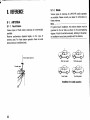
8. REFERENCE
8-1 . A N T EN N A
8-1-1. FixedStation
are commercially
Varioustypesof fixed stationantennas
available.
Receiver performance depends largely on the type of
antenna used. For fixed station operation there are wide
band antennas(omnidirectional).
8-1-2. Mobile
mobileoperation
for UHF/VHF
Varioustypesof antennas
on
Please
consultyourdealerfor information
areavailable.
these antennas.
Note:
For gutter-mountinstallation,the antennabracket must be
groundedto the car body as shown in the accompanying
diagram.Attach the antennasecurely,referringto the antenna installationinstructionsprovidedwith the antenna.
o-r^, ptane
antenna
I
-lF
Coaxialcable l{
---.dl
ffiH
7 r
32
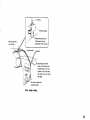
Roof top system
Roof s¡de svstem
.,1------¡r
r-Tt¿D\\
v@F::rep¿
Front fender
Trunk lid system
Installation for mobile operation
-1
;,=-
,Ta"
Passthrough the
rearwindow.
ove the pa¡nrfrom
these areasto insure
grounding to the car body
Coaxial cable
Passthrough the door
f¡tting. The cable can be
insertedeas¡lvif the door
cushion is soft. Note that
ra¡n water may enter along
the cable.
L¡ft the trim plate and
¡nstall the cable.
Coax. cable routing
33
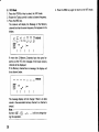
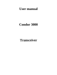
ALLOCATION
8-2. RADIOFREOUENCY
kHz
:::"
525
1606
17 0 5
1800
2000
2300
2500
3200
3400
3500
3800
3900
3950
4000
4750
5000
5060
2nd 3rd
Zone Zone
MHZ
]::"
2nd 3rd
Zone Zone
MHz
10 . 10 0
10.150
50.ooo
11.650
12.050
13 . 6 0 0
13.800
14.OOO
14.350
68.OOO
72.OOO
76.OOO
15.000
l 5 . 10 0
15.600
17.550
17.900
18.068
18 . 16 8
20.ooo
21.000
2 1. 4 5 0
21.850
24.890
24.990
25.000
25.670
2 6 . 10 0
28.OOO
29.700
3rd
2¡d
1st
Tone Zone Zone
54.OOO
B7.OOO
108.000
Standardtime f requencY
174.OOO
216.OOO
220.OOO
225.OOO
230.OOO
m
430.ooo
r
Amateurband
tl
Other stat¡ons
440.000
608.000
614.ooo
9900
10000
ln some countries, frequenciesallocations do not accordwith this table'
.
144.000
146.OOO
148.0O0
470.ooo
9500
1st Zone:
Europe and Africa (Soviet Russia' Turkey
and Mongoliaincluded)
2nd Zone:
South and North America
3rd Zone:
Asia and Oceania (Soviet Russia' Turkey
and Mongoliaexcluded)
890.Ooo
902.OOO
905.000
Broadcastband
KENWOOD