1
TABLE OF CONTENTS
Page
INTRODUCTION
GETTINGSTARTED
UNPACKING
MOUNTINGBRACKET
INSTALLATION
POWERCONNECTIONS
MOBILEPOWERCONNECTIONS
BASEPOWERCONNECTIONS
ANTENNA
QUICK REFERENCE
CHART
QUICKREFERENCE
CONTROLFUNCTIONS
FRONTPANEL
DISPLAY
REARPANEL
REMOTECONTROL
BATTERIES
FUNCTIONS
OPERATION
FACTORYPROGRAMMEDMODE
POWERON, VOLUMECONTROL,AND
SQUELCHCONTROL
VFOMEMO MODE
SCANMODE
VFOSCANNING
MEMO SCANNING
RESUMESCANNING
J
4
4
4
5
6
6
7
8
9
10
11
11
r3
tl
18
18
t9
22
22
22
23
25
25
26
26
TABLE OF CONTENTS
. CONTINUED.
COPYMEMO CHANNEL
SKIPMEMO CHANNEL
CLEAR(ERASE)MEMOCHANNEL
MEMOGROUPSCAN
BAND SCAN
TIMERMODE
PRIORTYMODE
ALARM MODE
RESETMICROPROCESSOR
OPTIONALRS.232C
FACTORYPROGRAMMEDMODE
FACTORYPROGRAMMEDMODE CHART
SPECIFICATIONS
GENERAL
RECEryER
SROO1
QUICK REFERENCECHART
Pase
29
29
3r
31
34
36
38
39
40
40
40
4l
42
42
43
45
INTRODUCTION
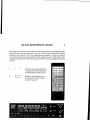
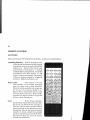
The Shinwa Model SR001Wide Band ScanningReceiveris a state-of-the-art,
synthesizedreceiverthat is designedto provide you with years of dependable
serviceand listeningpleasure.The scanningreceivercovers25 through 999.995
MHz and provides200 programmablememory channels(10groupsof20 channels
each). A full-featuredwirelessremote control is also included to operate the
receiverfrom the relaxation ofyour easychair. The following features provide for
optimum performanceof all receivedfrequencies:
o
a
o
a
o
a
o
o
o
a
o
Wid e-BandFrequencyCoverage
High-SpeedScanning
o
35-Ch/ Secin VFO Mode
25-Chi Secin MEMO Mode
|
200 MEMO Channels(10 Groupsof 20 Channels)
Pre-ProgrammedMode By FrequencySegment
ProgrammableScanfor:
MEMO ChannelScanning
.
MEMO Group Scanning
.
.
MEMO Band Scanning
^,,,I
t
ResumeSaan
Timer (On or OfI) Mode
Alarm Priority Channel Monitoring
Easy-To-Read
MultiColor LCD Display
WirelessRemoteControl
Two Antenna Jacksfor Optimum Antenna Selection
Lithium Battery Memory Back-Up
Thesefeatures combineto provide you with one of the finest scanningreceivers
available.Pleaseread this manual thoroughly sothat you will becomefamiliar and
comfortablewith the operation and programming examples. This will help you
achievemaximum performanceand enjoyment while using the receiver.
THANKYOUFORCHOOSINGTHE SROO1
WIDE-BAND
SCANNINGRECEIVER!
Note: Any information monitored on this receiveris for your personaluse only and is not
intendedforcommercialpurposes.
Pleasefollowallappiicablegovernmentregulgtionsthat
apply to radio frequencybroadcastsand reception.
GETTING STARTED
TINPACKING
Carefullyunpackthe receiver,remotecontrol,and all otheraccessories
listedbelow.
check eachitem against the followingparts list, and look for any shipping
damage
that may have occurred.
PART d
DESCRIPTION
SROOl
SD471
UM-4
ScanningReceiver
RemoteController
Batteries for SD471(AAA)
Mounting Bracket
PowerCable(DC)
HardwarePackage(s)
Hook & LoopTape
2 Amp Fuse (extra)
Label Set
Warranty Card
zK82
OUANTTTY
1 ea.
1 ea.
2 ea.
1 ea.
1 ea.
2 ea.
1 ea.
1 ea.
1 ea.
1 ea.
MOTTIVTINGBRACKET
HARDWARE PACKAGE #1
X[4 X 10 mm
Hex phillips HeadBolt (black)
4 ea.
HARDWARE PACKAGE #2
M5 x 16 mm
NIs
M5
M5
#5 x 25 mm
Hex phillips Head Bolt
Flat Washer
Split SpringWasher
Hex nut
Pan Head Self TappingScrew
4 ea,
4 ea.
4 ea.
4Ea.
4 ea.
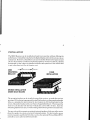
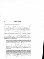
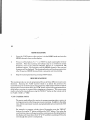
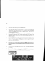
INSTALI,ATION
The SR001Receivercanbe installedand usedin any positionwithout affectingits
performance.It shouldbeinstalledsothe digital displayand controlsare easyto see
and operate.However,it shouldhaveat leasttwo inches(50mm) of air spacearound
the rear heat sink for ventilationand heat dissipation.If usedin a vehicle,it should
be mountedso that it doesnot interferewith the safeoperationof the vehicleand
is not in the direct air flow ofa heater vent.
MOUNTING
BRACKET
FIXED
INSTALLATION
MOBII.EINSTATTATION
UNDER
DASHBOARD
The mountingbracketcan be installedon top of the receiver,or under the receiver
asa stand.If youdesireto permanentlyinstall the bracket,usethe mountingbracket
holesas a templatefor determiningthe best locationto drill starting holesfor the
screws.Mount the bracketwith your choiceof suppliedhardware. Then mount the
receiverto the bracketwith the four (4) black hex screws(M4 x 10 mm). Savethe
remaininghardwarein caseyou wishto changethe mounbinglocationat a later time.
You may alsowish to connectan optionalexternalspeakerwhich may allow you to
placethe speakerin a more convenientlisteninglocation. For bestresults,use an
externalspeakerspecifiedat BQ (ohms)suchas the optionalShinwa Model ZP72l
availableat your authorizedShinrvaDealer.
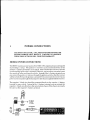
POWER CONNECTIONS
GROUND ONLY OR
CAUTION: USE 13.5VDC, !70Vo,NEGATM
SEVERE DAMAGE WILL RESULT! FAILURE T:O OBSERVE
TH E SB PRECAUTIONS WILL V OID TH E WARRANTY.
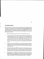
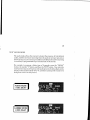
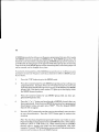
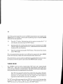
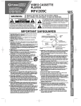
MOBILE POWER CONNECTIONS
The SR001requiresa powersourceof 13.5VDC +707o,negativeground,and capable
of providing 1.5 amps. The positive(+) red wire can be connecteddirectly to the
positive (+) battery terminal in your vehicle.This will allow the receiverto operate
However,youmustthenremembertoturn
eventhoughtheignitionkeyisturnedoff.
the receiveroffwhen you leavethe vehicle. Insteadof the (+) battery terminal, you
can connectthe positive(+)red wire throughthe ignition switchsothat the receiver
will be turned offwhen the ignition is turned off. Do not connectthe receiverto any
powersourceexceptthroughthefusedpowercablethat is suppliedwith the receiver.
The negative(-) black wire shouldbe connecteddirectlyto the negative (-) battery
terminal in your vehicle. Instead of the (-) battery terminal, you can connectthe
negative(-) black wire directly to the metal vehicle chassisif the chassisis actually
the sameas the negative(-) battery terminal.
vEHtctf
rUSEBOX
IO VEHICTE
BAITERY
+13.E
VDC
TUSEHOIDER
RED
WIRE
Bt-ACX
WIRE
7'
)
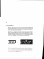
BASE POWER CONNECTIONS
The sR001requiresa powersupplyof 13.5vD C +\\qn,negativeground,and capable
of providing1.5 amps. Connectthe positive(+) red wire to the positive(+) voltage
connection,and the negative(-) black wire to tbe negative(-) voltageconnection.If
the output voltageof the powersupplycanbevaried,setit for nomorethan 13.5VDC.
Do not connectthe receiverto any powersourceexceptthrough the fusedDC power
cablethat is suppliedwith the receiver.
The powersupplycanbe turned On and Offeachtime the receiveris turned On and
off, butthereceivermustbeturned on afterthe powersupplyisturnedon, andthen
the receivermust beturnedOffbeforethe powersupplyis turned Off. This procedure
will not allow you to use the wirelessremotecontrolto turn on the receiver.
The powersupplycan be left On sothat the receivercan then be turned On and Off
by the front panelswitchor rvith the rvirelessremotecontrol.Be surethat the power
supplyis rated to be left On continuously.
You may alsowish to use the optionalAC Adapter to power the receiverinsteadof
a separatepower supply. The AC Adapter providesthe correctDC voltageand
current to operatethe receiver,and it is availablefrom your Authorized Shinwa
Dealer.
POWET
sUPPI.Y
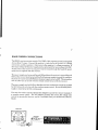
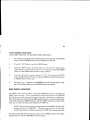
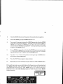
ANTENNA
8
All antennasare designedfor use on specificfrequencyranges. Antennasare also
designedto be extremely narrow band to covera very narrow frequencyrange,very
broadbandto cover a broad frequency range, or dual-band to cover two different
narrow bandsof frequencyranges. A narrow band antennawill typically provide
greater receivedsignal strength on the narrow frequencyrange it is designedfor as
comparedto a broadband antenna that typically offers a lower received signal
strength over a broader range offrequencies. Each antenna has its own specificationsfor gain, directionalor omni-directionalsignalpatterns,and mounting.
Your choiceof antenna(s)will make a significantdifferencein the sigaal strengthyou
receive.Ideally, you shouldconsideroneofthe speciallydesignedscannerantennas
that are availablein the market place. Theseantennasare manufactured by many
different antenna companies,and are available for base station mounting and
vehiclemounting. You may choicetwo different antennassoyou receivemaximum
signal strength on the particular frequenciesyou are interested in monitoring.
.-.@
-;
ffi*
O
|_-GL"c=l
;r
Your SR001Wide-BandScanningReceiverprovides
two separateantennajacks on
the rearpanel.Theantennainput impedanceof eachjack is 50O.Onejack is a "BNC"
connectorand the otherjackis an "N" connector.A singleantennacanbe connected
to either ofthe jacks,or separateantennascan be connectedto eachjack. Antenna
switching is done by the "ANT' (antenna) button on the remote control. While
programming the receiverfor a particular frequencyyou wish to monitor, you will
alsoprogramwhich antenna shouldbe selected.This allowsyou to program the most
sensitiveantennafor eachfrequencymonitor.
Your authorized Shinwa Dealer will be able assist you in selecting the best
antenna(s)for your applicationand listeningpleasure.
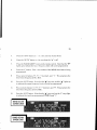
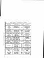
QUICK REFERENCE CHART
I
This chartisintendedasaquick referenceafteryouhave
becomecompletelyfamiliar
with all features and functions of the receiver. Pleaseread through all the control
functions and perform all of the programming examples to help you achieve
maximum performanceand enjoyment while using the receiver. The chart is also
repeatedin the back ofthe manual in caseyou wish to cut-it-out and keep it with the
receiver.
1.
Indicateswhat modeor function
is displayedon the LCD (Liquid
Crystal Display) of the receiver.
2.
Indicates what button on the
front panel or remotecontrol
shouldbe pressed.
SROO1QUICK REFERENCE CIIART
FUNCTION
OPERATION
MODE
ENTER
A FRE().
INTO TIIE
PRESS'EI{I''
ENTER Tr[t FREQ.
PRESS'ENT''
'vFo"
CIL\NGE TITE
FUNCTION OF
A PREVIOUSLY
ENTL'RED FIREQ.
PRESS'MODN'"
'STEP" OR'ANT''
TITEN CIIANGE
FUNCTION
'MODE",
'STEP"
OR
'ANT''
NOT POSSIBIJ
WHEN TTIE "." IS
DISPI.AYED
ENTERAT.RDQ
INTO A
MEMOITY'MEMO''
CTIANNF]L
SELECT TIIE FREQ.,
PRESS'M",
ENTER MEM CII #,
PRESS'ENT'
'MEMO''
OR
FUNCTION IS
POSSIBLE WHEN
TIIF "o" IS
FI,1\SIIING
w'o
i
R.ECALLING A
MEMORY
CIIANNET,WHEN
INITTO'IMODE
PRESS 'V/nif"'Slilf"
ENTER MEM CII #, &
PRESS'EN'I'; OR
'r6N'1r'&rr 'r OR
"V'r
n
RECAIIINGA
MEMORY
CIIANNEL WHEN
IN ''ME]!TO''MODE
PRESS'TNT'
ENTEIT MEM CH #, &
PRESS'ENT"; OR
'ENTil g rrfirr OII
"V"
PRESS'SCAI]""
1'0 SCIIN
PRIISS
rr
OR
PRESS
tt
{
!f
rr
tr
CTIANGE TTM SCAN
I.'UNCTION OF TIIE
RESUME SCAN
MODE
PRESS'SCAN.C''
TO SELECT ''CAFI'"
'AUD", OR ''rIM" AS
A SCAN MODE
SETTING THE
"oIY'OR "OFtr''
TIMER
FUNCTION
PRESS TIMER
"OiV'OR "OFI.-'
ENTER TIME,
PRESS'ENT"
ilat
ITEMARKS
SCANNING NOT
AVAILABLE WHEN
EIVI'IiRING A
FREQ.
POSSItsLE IF
TTIE "o" fS
NOT DISPLAYED
'vFO"
'TYIEMO"
I'OSSIBLE IF
TIIF "o" IS
NOT DISPLAYED
"a"
PRI'SS'SCA]Y'
ACNIN TO STOI'
TTIIS MODE
OR
ilV
il
"cAIl",
''AUI)'"
OR
''TIM'
TIIIS FUNCTION
CA]\'BE CHANGED
WIIILE INAIIY
MODE
"c"
MAXIMUM TTME IS
99 HRS & 59 MIN
FROM THE
PRESEIYT TIME
I
CONTROL FUNCTIONS
I
I
ll
The ControlFunctionsare dividedinto three sectionsthat describethe receiverits
self,and a fourth sectionthat describesthe remotecontrol. It is suggestedthat you
compalethe descriptionof eachfunctionshere with actualfunction on the receiver
the receiveris shownwithout its display
and remotecontrol.For your convenience,
Thisistoemphasize
functions,andthedisplayisshownwithouttheentirereceiver.
the controlfunctionsof one particular area of the receiverat a time.
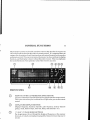
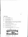
FRONT PANEL
REMOTE CONTROL INFRARED RECEIVER SENSOR
Locationof the infraredsensorthatreceivessignalsfrom the remotecontrol.
This sensormust alwaysbein a directline-of-sightwhen you usethe remote
control.
DISPI,AY (SEE DISPI,AY SECTION)
Displaysfrequency,function, channels,timer function, memory channel
groups,mode,channelsteps,scanrate, delay,and antennal or 2.
"n" AND "v" IJP AND DOWN BUTTONS
For steppingup or dolvn through the displayedfrequencyor tbe memory
channels,or to start scanningbypressingeitherbutton for morethan one(1)
second.
t2
"SCN" SCAN BUTTON
For starting and stoppingthe scanningfunction.
.\.,M" VFO/MEMORY BUTTON
and the
For switchingbetweenthe VFO mode(manuallyenteredfrequency)
(memory
mode
MEMO
clrannel).
"PWR,/VOL" POWER,/VOLUME CONTRO L (PUSH/PU SH TYI'E )
Forturningthe powerOnand Off,and controllingthevolumelevel.Pushing
the control oncewill make it pop out so it can be adjusted,and pushing it
againwill return it to its recessedposition.
" ?"EARPHONEJACK
For connectingan optionalearphonefor private listening when you do not
wish to listen to the speaker.IJsean earphonethat has a 3.5 mm plug and
30-600 O of impedance. When the earphoneis pluggedin, the internal
speakeris muted (turned off).
"SQ" SQUELCH CONTROL (PUSH/PUSH TYPE)
For controlling (quieting) the receiveraudio output when no signal is being
received.Rotatethe controlclockwiseuntil the noisedisappears.Pushing
the control oncewill make it pop out so it can be adjusted,and pushing it
again will return it to its recessedposition.
"ENTO'ENTERBUTTON
memorychannelnumber,skipmemorychannel,
For settingVFOfrequency,
band frequencysetting, timer, alarm channel, and alarm.
"M" MEMORY BUTTON
For setting the memoryfrequencies,memorynumber,and alarm channel.
"FM, TV, AND PRSNL'AND OTHER NIIMERIC BUTTONS
For programmingfrequency,and setbingmemorygroups.
l3
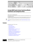
DISPLAY
o
lMEMol
@ f vFol
(MEMORYMODE)
Lights up in the memory mode.
(VFO MODE)
Lights up in the VFO mode.
@
ft
(SKIP MARKINDICATOR)
Lights up when a memory channelis programmed to be
skippedwhile in the scanmode.
@
A
(LP / DOWN SCANNING INDICATORS)
Indicates the VFO frequencyor MEMO (memory) channel
up or down scanningdirection.
@
E
V
(PRI MODE)
Lights up in the priority mode.
14
@ IALMI
(AIM MODE)
Lightsup in the alarm mode.
o
(COLONINDICATOR)
Lightsup whenthe timer ON/ OFFmodeis programmed.
I
I
@ I sKrPl
@ I prcll
(SKIPMODE)
Lightsup in the skip mode.
(DTGIMODE)
to the
Lights up when an externalcomputeris connected
jack on the rearpanel.
optionalRS-232C
@ I Brrsvl
(BUSYMODE)
Lights up when a signalis receivedwith a strongenough
signalstrengthto openthe squelch.
@
ON
(ONTIMER MODE)
TheON lightsup whenyoupressthe "ON"timer buttonon
the remotecbntrol,and the "ON" goesout after approxiwhenyoupressthe "ON"buttonagain.
mately2-seconds
OFF
(OFFTIMER MODE)
TheOFFlightsup whenyoupressthe "OFF'timerbutton
on the remote control,and the "OFF" goesout after
whenyoupressthe"OFF"button
2-seconds
appproxiamtely
again.
STRENGTHMETER)
@ llllnr*rrrllll(SIGNAL
Lightsup to show the signalstrengthof receivedsigaals.
ATT
(ATTSELECTIONINDICATOR)
Lights up whenyou pressthe "ATT''buttonon the remote
again.
the"ATT''button
control,
andgoesoutwhenyoupress
l5
-
OPTI
OPT2
(OP1 & OPT2 SELECTION INDICATOR)
Lights up when you presseither the "OPTION 1" or
"OPTION 2" button on the remotecontro.l.Pressingeither
the "OPTION 1" or "OPTION 2" button again causesthe
indicatorto go out.
ANT
(ANT SELECTION INDICATOR)
Lights up to displaywhich antennajack (ANT.I or ANT.2)
tl.rereceiveris currently programmedto receiveon.
il-l
r r:tS
rTrr-r iV
r l r r _ rN
(RESUME SCAN DEI"AY TIME INDICATOR)
Lights up to show the delay time that resume scan is
programmedfor, when in the TIM (time) mode.
(RESUME SCAN INDICATOR)
Lights up to display one of the resume scan modes:CAR
(carrier),AUD (audio),or TIM (time) that the receiveris
currently programmedfor.
(FREeuENCyDrspr,ay)
@ 'l E Er:!ltr!:r.Lril!
Digital display that displaysthe receivedfrequencyin the
VFO or MEMO modes.or the time when the timer modeis
activated.
1 - tt - t r - l
(FREQUENCY STEP INDICATOR)
Displaysthe frequencystep(5.0,10.0,72.5,20.0,25.0,
50.0,
or 100k) that the receiveris currently programmedfor.
i-lMti l {r
(MODE INDICATOR)
Lights up to show what mode (AM, FMN, OR FMW) the
receiveris currently programmedfor.
a
(FREQUENCY ENTERING II.{DICATOR)
Lightsup whenthe "ENT''iruttonis pressedto indicalewhen
;t fre,luencv,
memoryclrannel,or aiarm shouldbe entered.
t I r t l r . r l rK
@ l;;;3
{<
(MEMORYGROUP/BANDDISPI,AY)
Lights up when a programmedmemory group or frequency
band is beingreceived.
(FACTORY-PROGRAMMEDMODE INDICATOR)
Lights up in the VFO mode when the frequency being
receivedis in a factoryprogrammedmodeinsteadof a user
programmed mode. Refer to the "Factory Programmed
Mode" chart
r-il-r r_t ^. (MEMORYCHANNEL)
l-l l-l l-l UH Displaysthe numberof the memorychannelwhenin the
MEMO (memory)
mode.
t7
REAR PANEL
6)
\/
(^
\-/
G)
\/
"ANT.I"coNNECToR
For an "N" typeantennaconnector.
"ANT.2"coNNECToR
For a "BNC"typ" antennaconnector.
"EXT.sP"
coNNEcroR
For connectingan optionalexternal speakerthat has a 3.5 mm plug and is
rated at 4-B Q. When the external speakeris pluggedin, the internal
speakeris muted (turned off).
@
DC VOLTAGE POWER CONNECTOR
For connecting13.5VDC I 70% to powerthe receiver.
@
FUSEHOLDER (2A FUSE)
For a 2 arnp fuseto protectthe receivercircuitry.
@
RS.232C OPTIONAL CONNECTION
Locationof optionalRS-232Cjack for computercontrolof receiver.
r8
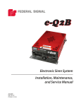
REMOTE CONTROL
BATTERIES
Beforeoperating
theWirelessRemoteController,
installtwo (2)AAA batteries.
InstallingBatteries:
Removethebatterycover
onthe backof the remotecontrolby pressing
downgentlyon the arrow and sliding offthe
battery cover. Note that the battery type
and direction of each battery is marked
insidethe battery compartment.Install the
two batteries with their positive (+) and
minus(-)polarityas indicated.The polarity
of the two batteries should be in opposite
directions.Replacethe battery cover.
Battery Life:
The batteries will last
approximatelysix (6) mont\,s dcpending
upon the usage of the remote controller.
Whenthe remotecontrollerwill not operate
the receiver, the batteries should be replaced.Always replaceboth batterieswith
new onesat the sametime. If the remote
controllerwill not be usedfor a long period
of time. removethe batteries.
Care:
If the remote controller
becomes
dirty, wipe it with a cleandry cloth.
Do not use any chemicalsfor cleaning,or
allow any water to comein contactrvith the
remote controlleras the buttons may stop
functioning. Also, do not leavethe remote
controller in direct sunlight for extended
periodsor in temperaturesover12OoF(49'C).
The excessiveheat may causethe remote
controller to malfunction.
l2Ja
IF'.'-
FXX'II F:-I
F'FI
5616
Irz=fl E;Er llllEl F==l
eo.T-;l=,;'3 tlEl
f=-z':| lE==
$nlAVlscri
F.'-=]lF=l.-l li-rTlFrffi
v/M [..::Ir{d€::::::::::::sEl
.,I{4!tC
r:lr:-]lr-1:r:...
::::::::::::::{ll0j:
l::illlrn::::::
,EH
:.:.:.:.:i.llttB:
:::fi:::::: :::l
j.j..
r*:'I'r-T:1
..:.::::::.:.:::: . :.
::::::::,f
{E::::::::i:::DErrr::::::
IlF;:tr#:
.,.,.,.,..^Il'''.,:,:,ii'.,fuq.,,,',.
.,liiiiil'i'.litiil.
' .-:P
::::::!rylt::::::::::i::::i$ql:::j:::::
;ETg
.
t9
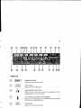
FLINCTIONS
1.
NUMERICBUTTONS
frequency,
timer on-off,andsettingmemorygroups.
For programming
"M" MEMORYBUT"ION
memorynumber,andmemoryskip.
For settingthe memoryfrequencies,
J.
"ENT''ENTERBUT'TON
memorychannelnumber,skip memorychannel,and alarm
For settingVFO frequency,
channel.
4.
"n" AND "v" IJP AND DOWN BUTTONS
For steppingup or downthroughthe displayedfrequencyor the memorychannels;or to start
scanningby pressingeither button for more than one (1) second.
5.
"SCN" BUTTON
For starting the scanfunction.
6.
.\i'l]VI"VFOA4EMO RY BUTTON
For switchingbetweenthe VFO mode(manually enteredfrequency)and the MEMO mode
(memorychannel).
q
"MODE" BUTTON
For selectingthe mode(AM, FMN, OR FMW) that you wish the receiverto operateon or be
programmedfor.
8.
"STEP"BUTTON
50.0,or 100k) that the receiveris
To changethe frequencysteps(5.0,10.0,12.5,20.0,25.0,
currently programmedfor.
9.
"SCAN.C" BUTTON
For selectingone
ofthreedifferentresumescanmodes;CAR(carrrier),AUD (audio),orTIM
(timer).
20
10.
"PRI"BUTTON
For settingor cancellingthe priority function.
11.
"ALM'BUTTON
For setting or cancellingthe alarm function.
12.
"SKIP" BUTTON
For selecting a memory channel(s) that you want to be skipped while
scanning,or cancellingthe skip function.
13.
"DEI"AY'BUT"TON
For setting the amount delay time that a channel is monitored beforethe
resumescanfunction starts scanningchannelsagain.
14.
"BAND LIMIT"'BUTTON
For setting the lower band limit and the upper band limit for the band
scanningfunction.
15.
..ANT'BUT"TON
For selectioneither "ANT 1" or "ANT 2" to receiveon.
16.
t;
i 1,
"ATf'BUTTON
For turning on or offthe receiverattenuator(-10db)circuit.
'1 4
r t.
"AUTO" BUTTON
For recalling the factory programmedmodethat has the frequency range,
mode (AM, FMN, or FMW), and channel step already programmed into
memory. Refer to the "AUTO PROGRAMMED" Iist in this manual.
18.
"TIMER ON / OFF" BUTTONS
The ON lights up when you press the "ON" timer button on the remote
control, and the "ON" goesout when you pressthe "ON" button again. The
OFF lights up when you pressthe "OFF' timer button on the remote control,
and the "OFF" goesout when you press the "OFF" button again.
2l
19.
"MUTE" BUTTON
For muting the audio (greatly reducesthe audio level until the mute button
pressedagain.
20.
"sq BUTTON
For opening the receiver squelchsetting that is set by the the front panel
"SQ" (squelch)control. Used primarily for receivingvery weak signals that
do not completly break (open)squelch.
21".
"OPTION1&2" BUTTONS
For selecting"OPTION1" oT"OPTION2" ifthese optionsare installedinthe
receiver.
22.
"M -) \T'BUTTON
For switching between the MEMO mode (memory channel) and the VFO
mode(manually enteredfrequency).
23.
"PWR" BUTTON
For turning the receiverppwer On and Off. Note: The front panel "PWR /
VOL" control must be turned On and power supply voltage must be applied
'P'WR" button will function.
beforethe remote
22
OPERATION
F'ACTORYPROGRAMMED MODE
The Factory Programmed Mode Chart lists the entire frequency range of the
receiver in segments. Each frequency segment is listed with the mode and
frequencystepthat the segmenthas beenprogrammedto operateon. This factory
programming has beenestablishedfor those modesand frequencycombinations
which are most commonon a world-wide basis. You will frnd that you will wish to
changesomeofthe modesand frequencystepsfor certain frequenciesin your area.
Refer to the Factory ProgrammedMode Chart in the Specification.
powER oN, VOLIIME COI{TROL, AND SQUELCH CONTROL
There are two different ways of turning the SR001ON and OFF. Be sure that the
receiveris connectedto a DC power sourcethat is On. The receivercan then be
burnedOn by either the PWWOL controllocatedon the front panel,or by pressing
the PWR button on the remote control.
1.
Rotatethe PWR/VOLcontrolclockwisefrom the click position and adjust the
volume for a comfortable listening level. Rotating the control counterclockwiseto the click position will turn Offthe receiver.
The remote control can also be used to turn the receiver On and Off.
However, the front panel PWMVOL control must be turned On for the
remote control to operate. First turn On the receiver with the front panel
PWVVOL control and adjust the volume for a comfortablelistening level.
The receivercanthen be turned Offor On by pressingthe PWR button on the
remote control.
3.
The SQ (squelch)control quiets (no audio noise can be heard) the receiver
when the receiveris turned On, but no sigaal is beingreceived. The proper
way to set the squelchto its proper thresholdlevel is to rotate the front panel
(SQ)squelchcontrol clockwiseuntil audible noisedisappearsand the green
BUSY light on the front panel so-es-pq_t.
There is also a SQ button on the
remote control. Pressing this button will open (noise will be heard) the
squelchor close(no noisewill be heard) the squelchback to its preset level
that was set by the front panel SQ (squelch)control.
23
VFO/IVIEMOMODE
Each frequencythat you wish to listen to must be programmedinto the VFO before
thatfrequencycanbe storedin oneofthe 200availablememories(MEMO mode).For
an example,the National Weather Servicefrequency of 162.550MHz will frrst be
programmedinto the VFO, and then storedinto memory(MEMO) channel185.The
receiverwill then be switchedfrom the VFO modeto the MEMO modesothe memorv
channelcan be recalled.
NOTE: TheNational WeatherSeruicefrequencynny bedifferentin your area.
1.
Setthe receiverto the 'VFO" modeif it is not alreadyin that mode.The front
panelshoulddisplayeither"VFO" or "MEMO". If it is in the "MEMO" mode,
pressthe 'VIM" button on the front panel and the function should changeto
'"VFO".If the function still doesnot change,
the receivermay be in the scan
modewhich is indicatedby either an "A " or 'V " on the front panel. Press
the "SCN" button on the remotecontrol,and the arrow should disappear.
Then press the "V/1VI"button and the receiver should switch to the '1II'O"
mode.
2.
Repeatedlypressingthe"MODE"button will stepthrough modesFmW, Am,
and FmN, soyou can selectthe modeyou desirefor the frequencyyou have
programmed. Now select"FmN" which is the correctmodefor the national
weather frequency.
Repeatedlypressing the "STEP" button will step through frequency steps
5.0, 10.0, 72.5,20.0,25.0,50.0,or 100 kHz, so you can selectthe correct
frequencystep for the frequencyyou have programmed. Now select"10.0
kHz" which is the correctfrequencystepfor the national weather frequency.
4.
Repeatedlypress the "AUTO" button and note that the " {c " indicator will
light and then goesout. When the " * " indicator is on, the receiveris in the
FactoryProgrammedMode*hich is shownin the chart in the Specifications
section. Now press the "AUTO" button and turn offthe " * " indicator.
24
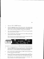
5.
Repeatedlypress the I'IUVTD'
button which will alternately switch between
"ANT.1" and "ANT.2". Now selectthe antenna that you will use for this
frequency.
6.
Pressthe "ENT"'button which will causethe numeric frequencydisplay to
go blank and the "o" indicator to light.
7.
Enter the frequency 'teZ.SS"by pressingthe numberedbuttons (onthe front
panel or the remote control) exactly in order including the decimal point.
Then pressthe "ENT''button. This will enter the frequencyin the "VFO" and
the "a" will go out.
8.
Now storethe frequencyinto MEMO channel"185"by first pressingthe "M"
button. Thefrequencydisplaymaysuddenlychangeand displaya different
frequency(the lastfrequencythatwas displayed)than the frequencyyouare
storingin memory.
o
Select MEMO channel "185" by one of two ways. First, by pressing the
numberedbuttons and then "ENT"'. Sqgnd, by p ressing either the "n' or uv'
button to start scanningtoward the fvftflid.ttaffi
that y6-uwaii
to store the frequencyin, and then the "SgJ.{"button"ftner
on the remote control
to stop scanning. If you pass the MEMO channel you wish, momentarily
pressthe "A"or "v" button to stepto the actualchannelyou wish. Then press
the "ENT'button.
REPEATEDTY
PRESSING
IHE
'vlM"
BUTTON
SWIICHES
BETWEEN
IHT VFO MODE
ANDTHEMEMOMODE
25
SCAN MODE
NOTE: The receiverhas 200 MEMO channelsavailable which are groupedinto ten
(10)groupsoftwenty(20)channelseach.
Afrequencycanbestoredintoanyoneof
the 200 channels.However,the receiveralsohas a Group Memory Scanfunction. It
is possib)eto scanoneor morespecificgroupsoftwenty (20)MEMO channelswithout
scanning all ten (10) MEMO groups. Therefore, you may wish to assign specific
frequenciesinto particular MEMO groups.
Frequenciescan be classifredinto many different types of transmissions. They
includethe National WeatherService,commercialFM broadcaststations,government, business,aviation,and amateur radio, among others. Stationssuch as the
National Weather Serviceand commercialFM stations transmit continuously so
there is alwaysa carrier frequencythatwill always stopthe scanningfunction.Other
stations only transmit when communicationsare necessary.Therefore,it may be
desirableto programsimilar typesof stationsinto the sameMEMO channelgroup
so you can more easilyscanfor particular frequencies.
\rFOSCANNING
1.
RepeattheVFO/IVIEMOprogrammingstepstoprogramotherfrequencies
ofyour choiceinto the VFO, and then storethem in MEMO channelsthatyou
may designateby MEMO groups.
2.
Press the "V/II" button so the receiver is in the VFO mode and note the
frequency shown on the display.
3.
Press the "SCN" button to start and stop the scanningfunction. Note that
the "1" or the " V " will be indicated on the display indicatingthe scanning
direction is either up or down in frequency.
4.
The scanningfunction may also be started by pressingeither the "r" button
to scanup in frequency,or the'v" button to scandown in frequency. Stopthe
scanningfunction by pressing "SCN" button.
26
MEMO SCANNING
Press the "VNI>'button so the receiveris in the MEMO mode and note the
MEMO channel shown on the display.
2.
.J.
Pressone of the buttons ("A","v", or "SCN")to start scanningthe memory
channels. Note that scanningwill always stop on a continuouscarrier
frequency such as the National Weather Service or a commercialFM
broadcaststation. The frequencyand the MEMO channelof the received
frequencywill bedisplayed.The scanningfunctionwill continueon pastany
other frequency(MEMO channel)that is presentlynot transmitting.
Stop the scanningfunction by pressing"SCN" button.
RESUME SCANMNG
The scanningmodecan alsobe programmedfor one of three differentresumescan
functions. Scanning for: "CAR" (carrier) which is to detect the presenceof a
transmitted carrier on the frequen'cybeingreceived;"AUD"(audio)which is to detect
the presenceofintermittent audio;and "TIM" (timer)whichis the programmedtime
delay beforescanningis resumedafter stoppingon a frequency.The resumescan
modeis selectedby repeatedlypressingthe "SCAN.C"button on the remotecontrol
for "CAR", "AIJD", or "TfM".
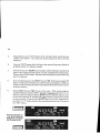
"CAR" (CARRIER)MODE
The carrier mode allows the receiverto resume scanningwhen a carrier is
no longerpresenton the frequencyyou are receiving.In addition;the delay
time, beforescanningisresumed,is programmableup to a maximum of19seconds.
For example, to program a delay time of 2-seconds;press the "DEI,AY"
button, the number"2" button, and then the "ENT'button. Now when the
scanfunction stopson a frequencywith a carrier present,the delay digits on
the display will count down from "2" to"0", and then scanningwill resume
even though the carrier is still present.
27
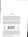
"AUD" (AUDIO) MODE
The audio mode al.lowsthe receiverto detectthe presenceof intermittent
audio,and then to resumescanningwhen the audiois no longerpresenton
the frequencyyouare receiving.In addition;thedelaytime, beforescanning
is resumed,is programmableup to a maximum of 19-seconds.
For example,to program a delay time of 5-seconds;press the "DELAY"
button,the number "5" button, and then the "ENT"'button. Now when the
scanfunctionstopson a frequencywith audiopresent,the delaydigitson the
displaywill countdownfrom'5" to'0', and then scanningwill resumeeven
though the carrier is still present.
AUDIOMODE
5-SECDELAY
CARRIER
MODE
2.SECDETAY
28
"TIM" (TIMER)MODE
The timer modeallows the receiverto resumescanningafter a programmed
delaytime eventhough a carrier and audio may bepresenton the frequency
you are receiving.The delaytime, beforescanningis resumed,is programmableup to a maximum of l9-seconds.
For example,to program a delay time of 19-seconds;press the "DELAY'
button,the numeric buttons"l" and "9", and then the "ENT'button. Now
when the scanfunction stopson a frequencywith audio present, the delay
digitson the displaywill countdownfrom "19"t0 "0", and then scanningwill
resume even though the carrier and audio may still be present.
TIMER
MODE
I9'SECDELAY
NOTE: Each frequencythat is programmed into a MEMO channel can be
programnledfor a particular resumescanmodebestsuitedfor that particular
frequency. After becomingfamiliar with the characteristicsof each scan
mode,you may wish to changethe modeand delay or frequenciesyou already
haueprogrammed in the MEMO channels.
29
COPYMEMO CHANNEL
(ONEMEMOCHANNELTOANOTHER
MEMOCHANNEL)
l.
For example,transferthe NationalWeatherServicefrequencyof162.55kHz
that is storedin MEMO channel185 to MEMO channel100.
2.
Pressthe "V44" button to so to the MEMO mode.
Pressthe "ENT" button; numeric buttons "7","8", and "5"; and then the
"ENT. button. Note:Do not use the "n" or "v" buttons to selectthe MEMO
channelas the MEMO channelwill not copyproperly.
^
Press the "M" button; numeric buttons "7","0", "0"; and then the "ENT'
button.MEMO channell85 is now copiedto MEMO channel100,and is still
in MEMO channell35 as well.
5.
Now use u,.' or "v'buttons to selectMEMO channels100 and 185 to verifv
the 162.550kHz copiedfrom oneMEMO channelto another.
a-
SKIP MEMO CIIANNEL
The "SKIP" memo function allows a particular MEMO frequencyto be bypassed
(SKfP) while scanning. This is important for frequenciessuch as the National
Weather Servicewhich transmits a carrier frequencywith audio on a continuous
basis.This is the samefor commercialFM broadcaststations.You may wish to mark
a particular frequency(MEMO channel) with the "SKIP" indicator so that during
scan,you can chooseto stop on this frequencyor "SKIP" it.
NOTE: Only frequenciesthat dre programmed into MEMO channels 180
through 199 can be "SKIPPED". Therefore, you. may wise to use these
memoriesfor freq uencies t hat y ou may w i sh to "SI{[ P" later d uring scanning.
The National Weather Servicefrequencythat is now in MEMO channel 100 will be
programmedso it will be "SKIPPED" during scanning.
30
1
Pressthe .'VNI" button to go to the MEMO mode.
Pressthe "ENT''button; numeric buttons "I","8", and "5"; and then the
"ENT'button. Note: Do not use the "n" or "v" buttons to selectthe MEMO
channelas the MEMO channelwill not "SKIP" properly. You have now
recalledMEMO channel185.
3.
Pressthe "M" button,the "SKIP" button, and then the "ENT''button. The
skip mark indicator (curvedarrow) will now be indicatedabovethe "CH"
MEMO channels.
4.
Pressthe "SKIP" button on the remotecontroland note that "SKIP" (word)
lights on the display. When "SKIP" lights, the frequencywill be skipped
during scan. When "SKIP" is not lighted (curvedarrow still showing),the
frequencywill not be skipped.
5.
Pressthe "n" or "v" button and step through all MEMO channelsthat you
have programmed.Note that MEMO channel185 is skippedand no longer
appears.
b.
Pressthe "SKIP" button again and notethat "SKlP" is no longershowingon
the display.
7.
Pressthe "A" or "v" button and step through all MEMO channelsthat you
have programmed.Note that MEMO channel185 now appears.
SKIPMEMORY
CHANNEL
31
CLEAR (ERASE) MEMO CHANNEL
Now that MEMO channel 185 has been copiedto MEMO channel 100, MEMO
channel185 will be cleared.
1.
Pressthe "VilU" button to go to the MEMO mode.
2.
Pressthe "ENT" button; numeric buttons "1","8", and "5"; and then the
"ENf button. Note: Do not use the'n" or "v'buttons to selectthe MEMO
channelas the MEMO channelwill not clear properly.
e)
Pressthe "M" button and then the "ENT'button.
4.
Now use the 'n" or'v'buttons to verify that MEMO channel185 has been
clearedand that frequency162.550kHz is still in MEMO channel100.
MEMO GROUP SCAN
The two hundred (200) memoriesof the receiver are divided in ten (10) groups of
twenty (20) MEMO channelseach. Any frequencyusing any mode, frequency
stepping,resumescandelay,or antennaselectioncanbe programmedinto any one
of the MEMO channels. The only considerationare frequenciesthat you may wish
to "SKIP" while scanningas discussedin the SKIP MEMORY CHANNEL section.
NOTE: Only frequenciesthat dre programmed into MEMO channels 180
through 199 can be "SKIPPED". Therefore, you n'Laywise to use these
memoriesfo r fre quencies t hat y ou may wi sh t o "SKI P" later d uring scanning.
The MEMO groups are divided into ten (10) groups as follows:
Group0
Group1
Group2
Group3
Group4
000-019MEMO Channels
020-039MEMO Channels
040-059MEMO Channels
060-079MEMO Channels
080-099MEMO Channels
Group 5
Group 6
Group 7
Group 8
Group 9
100-119MEMO Channels
120-139MEMO Channels
140-759MEMO Channels
i60-179 MEMO Channels
180-199MEMO Channels
32
A MEMO group only has to have onefrequencyprogrammedinto one of its twenty
(20)MEMO channelsto qualify as a MEMO group. Each MEMO group of ten (10)
channelscan be scannedas a separategroup,all MEMO groupscan be scanned,or
a combinationof somegroupscan be scannedwhile other groupsare not scanned.
Your choiceof which MEMO groupswill be scannedtogether,and which groupswill
not be scanned,can be changedat any time.
To realizethe full capabilitiesofthe MEMO groupscanfunction,ibwill benecessary
to programat least onefrequencyeachinto at leastthree differentMEMO groups
ofyour choice.
I
Pressthe "V44" button to go to the MEMO mode.
2.
Pressthe numeric button for eachMEMO group that you have a frequency
programmedinto. Example:Pressthe "5" button becausewe previously
copiedthe NationalWeatherServicefrequencyof 162.550kHz into MEMO
channel 100. Note that a small number "5" lights up on the display under
the MEMO channel numbers.
3.
Press the numeric bntton. for any MEMO groups that you have programmed frequenciesinto.
4.
Pressthe " ' or "v" button and step through all MEMO channelsthat you
have programmed. Note that everyMEMO channelyou have programmed
should appear unless you again press "SK[P". Then the skipped MEMO
channel will not appear.
Pressthe "SCN"button and notethat scanningimmediately
startsin either
an up or down direction. Press tbe "SCN" button again to continue the
scanning.
Note: You may haueprogranxmedparticular resumescan modeson some
frequenciesthat you haueprogr&mmedinto MEMO channels.Someof these
modesare "AUD" or "TIM" delays,etc. When scanning stopson a MEMO
channel where a resun'Lescan mode has beenprogrammed, that mode
(example:l2-second "TIM" delay beforeresumescan)will takepriority before
scannins will continue to the next MEMO channel.
>.
33
6.
Note the MEMO channeland frequencythat scanninghas stoppedon.
7.
Note what MEMO group that MEMO channelis in.
Pressoneof the numericbuttonsfor a MEMO group other than the MEMO
groupthat scanninghas stoppedon. (Example:If scanninghas stoppedon
MEMO channel100,that is MEMO group"5". Pressthe numeric"5" button
and notethat tbe MEMO groupnumber"5" will not goout becausescanning
stoppedin that MEMO group.)
9.
PressaMEMO groupnumberotherthantheMEMOgroup you arepresently
in. Note that the MEMO group number you pressedgo out on the display
indicating that you can no longerscanthat MEMO group.
10.
Pressthe "n" or "v" button and continuescanningthrough all MEMO channels that you have programmed.
11.
Pressthe "SCN" button again to stop scanning.
12.
Repeatedlypressthe "V/M" button to go to either the VFO or MEMO modes.
Followingthisprocedure,you canaddor deletewhatftequenciesyouwish programmed
into MEMO channels,what particular resume scan modes (if any) you wish
programmed for that frequency, what MEMO group you wish that frequency
programmedinto, and what MEMO groups you want included in your MEMO
channel scanning.
MEMOGROUP
SCAN
34
(
BAND SCAN
The Band Scanmodeprovidesten (10)MEMO bandsthat can be programmedfor
scanningwith your specificband limits. You can program each MFIMO band
independentlywith your specificfrequencyrangesand modes.TheseMEMObands
are in additionto the 200 MEMO channelsand 10 }{EMO groups.
The front panelof the receiveralreadylras buttons"I","2", and "3" markedwith
"FM", "'lV', and "PRSNL". The programmingexamplethat follows will program
bandin
F-MLrroadcast
butlon"1" (frontpanelor remotecontrol)for the commercial
with freqr:ency
the UniterlStates.You nrayrvith to programthe olher MEMO br,rnds
are
rangesand modesthat particularlyinterestyou. Frequencyband suggeslions
ar.iation,amateurraclio,publicsafety,TV, and c<lmmerciir'l
businessrtrclio.
progruntmi.ng
the
Note:Befbre
apctrticularMEMOband,you mustd.eternin.e
you tuiLLrec'eiue
in thct
specificnndes thut LaiLlbe ttsedfbr all frequenci,es
bunrl. Modes incI ude:AM, FmW, and FmN ; fr equencystepp i ng : resunte scan :
and antennaselection.,
TlrecommercialFM broadcastband,which is 88.1-107.9MH2,will be programmed
into MEMO band "1" as follows:
1.
Pressthe "VA{" button to go to the VFO mode.
2.
Pressthe "MODE" button and select"Fm'W".
3.
Pressthe "STEP"button and select"l00.0 kHz".
4.
Press the "SCAN.C"button and select"TIM". Then press the "DELAY"
button, the "3" butto n, and the "ENT" button. N ote:A resumescandelaytime
of three (3) secondshas beenprogrammed. The "SCAN.C"modesof "CAR"
and "AUD" cannot be usedfor the commercialFM broadcastband. These
stations transmit both a cclrrier frequency and au.dio 1007oof the time.
Therefore,only the "TIM" modewill allow resumescanafter a programmed
time delay.
35
Pressthe "AN'f'button an rilleit the antennaof your choice.
t'.
Pressthe "AU'IO" button a ,d be sure that the "4 " is 0ff.
7.
Pressthe "BAND LIMIT" b,rttonon the remotecontrol. Note that the "Y"
lights up to indicatethe lower frequencylimit will not be programmed.
8.
Pressthe "1" button. This rs Lhenumberof the MEMO band that is being
programmed.
9.
Pressnumeric butt0ns "8", "8", """ (decimal),and "1". This programsthe
lower limit frequencyof 88.1IVtlIz.
10.
Pressthe "ENT' button. Note that the "f " goesout, and the "A " lights up
to irrdicatethe upper frequencylimit will now be programmed.
11.
Pressnumericbuttons"1", "0","7" "." (decimal),and "9". This programsthe
lorverlimit frequencyof 107.9MHz.
L2.
Pressthe "ENT' button. Xot" tf,uf the "l " goesout, but the "1" stayslight
to indicatethat you haveprogrammedMEMO band"1".
BANDSCAN
LOWERLIMIT
BANDSCAN
TIMIT
UPPER
36
Note:Theprogrammingforthe commercialFMbroadcastband isnow completewhen
MEMO band "7" is recalled. Proceedwith the following stepsto recall this MEMO
band and scanthefrequencies.
13.
Pressthe "1" button. Scanningmay start as soonas you pressthe "L". If
scanningdoesnot start, press the "SCN" button.
14.
Note that when the scanningstopsand a frequencyis displayed,the "TIM"
"DE["AY'digits count down from "3" to"l", and then the receiverscansuntil
stoppingon the next frequency.
15.
Stop the scanningby pressingthe "SCN" button. The receiverthen returns
to the'VFO" mode.
This same programming procedurecan be followed to program the other MEMO
bandswith frequencyranges and modesthat particularly interest you.
For quick reference,you may wish to install labels(suppliedwith the receiver)above
the buttons on the front panel to personalizethe MEMO bands or groups.
TIMER MODE
The "TIMER" mode has both a programmable "ON" timer and a progtammable
"OFF" timer. Each timer can be programmed independently of the other for a
maximum time of 99-hoursand S9-minutes. The timers also function independent
of any mode that may be programmedin the receiver.
Note:Thetimers operateby elapsedtime rather than time-of-day.Example:
If the time is B:00P.M., and you tuish the timer to turn "ON" the receiuerat
6:30 A.M., you will program the timer for "10:30"hours and minutes of
elapsedtime rather than the actual time of 6:30A.M.
The "ON" timer will be programmedto turn "ON" the receivertwo (2) minutes after
you press the "ENT'' button. Then the "OFF" timer will be programmed to turn
"OFF" the receivertwo minutes after vou Dressthe "ENT''button.
37
l.
Selectany "VFO" or "MEMO" frequency.
2.
Press the "TIMER ON" button on the remote control. Note that the clock
symboland "ON" lights, and the display changesto a clock format with
hours,minutes,and a colondisplayed.All zerosare also displayed.
J.
4.
Pressnumericbutton "2" This programsan "ON" time of 2 minutesfrom the
time you pressthe "ENT"'button.
Presstlre "ENT'button. Note that the receiverturns "OFF". but the clock
symboland the word "ON" stayslight.
N ote: 1'h e t imer i s now counting t he elap sed t ime from 2 -min utes to zero. The
receiuerwill then tunt-on at the end of the 2-minutes.
TIMERMODE
2 - M l N" O N "
Now that the receiverhas turned-on,an "OFF" time will be similarly programmed.
5.
Pressthe "TIMER OFF" button on the remote control. Note that the clock
symbol and "OFF" lights; and the display changesto a clock format with
hours,minutes,and a colondisplayed.All zerosshouldbe displayed.
Press numeric button "2" This programs an "OFF" time of 2 minutes from
the time you pressthe "ENT'button.
4.
Pressthe "ENT''button.Note that the clocksymboland the word "OFF" are
still displayed,but the displaychangesbackto the programmedfrequency.
Note: The cloch is now counting down from 2-minutes to }-minutes. The
receiuerwill then turn-on at the end of the 2-minutes.
38
PRIORITY MODE
The pricrity feature providesfor periodiccheckingofcarrier and audio activity on
onefrequencywhile listeningto anotherfrequency.The priority channelis MEMO
channel"000";while the otherfrequencycanbein the VFO mode,the MEMO mode,
or frequenciesbeing scanned.When a signalappearson the priority channe.l,the
receiverautomaticallyswitchesto the priority channel.
intervals)for
Whenthe receiverchecksthe priority channel(approximately5-second
activity,it is actuallycheckingforthe presenceof a transmitted carrier with audio.
Ifthe carrierand audiois present,the priority channelis monitoreduntil the instant
the audio disappears. The receiverthen continuesmonitoring whatever other
frequencyor modeyou programmed.
the audiowill disappearmomentarilywhen a
During a normalradio conversation,
personstopstalking.This lvill causethe receiverto instantly switchfrequencieseven
if you wish to continuemonitoringthe priority channel. Therefore,it is suggested
using the "CAR" mode. This
that you programa resumescandelay of 5-seconds
no'rmal
in
time
for
breaks
conversation.
typicallyallowssuffrcient
1.
Pressthe "YllVf' button to go to the VFO mode.
2.
Programa "CAR" scanresumedelaytime of 5-seconds.
2.
Programtbe other modesfor the priority frequencyyou will enter.
3.
Pressthe "ENT''button, and program a priority frequencyof your choice.
*v"
Then pressthe "ENT"'button again. Note:Do not usethe "n' or
buttons
to selectaWO frequencyas the priority mode will not function properly.
4.
Press"M", priority MEMO channel"000",and "ENT''. This programsyour
frequencyand modesinto the priority MEMO channel.
5.
Now selectany otherfrequencyin theVFO mode,MEMO mode,or scanmode
thabyou wish to monitor.
39
6.
Pressthe "PRI" button. Note that the display flashesmomentarilyabout
every 5-secondsas the receiverchecksthe priority channel.
7.
To cancelthe priority function, press the "PRI" button.
AI"AR,MMODE
The alarm modeoperatessimilarly to the priority mode,exceptthat when activity
is detectedon the alarm channel,a LOUD audio beepingand FI"ASHING display
occursfor S-seconds.
This is to alert you that a transmitted carrier with audiowas
detected.During the bpeping,you will not be ableto hear the receivedaudiounless
you pressany button on the remotecontrolto cancelthe beeping.
1.
Pressthe "V/W button to go to the MEMO mode.
2.
Pressthe "ENT"' button.
3.
Pressthe "ALARM" button.
4.
Selectthe MEMO channelthat you wish to designatethe "ALARM" channel.
You must the "n" or "v" to selectthe MEMO channel.
Pressthe ".ENT"'button.
6.
Pressthe "ALARM'button to activate the alarm mode.Note that the display
flashesmomentarilyaboutevery5-seconds
as the receiverchecksthe alarm
channel.
4
Now you can selectany other MEMO channel,VFO channel,or scanother
frequencies.
Whenth e alarm channeldetectsa carrierwith audio.the alarm
is activated.
8.
Cancelthe alarm mode by again pressingthe "ALARM" button.
L
/
40
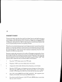
RESET MICROPROCESSOR
modes,andfunctions
all frequencies,
Resettingthemicroprocessor
completelyresets
to originalfactoryprogrammingfaults. This shouldonly be necessaryin caseof a
severeoperationalproblemtbat may be causedby the microprocessor.Normally,
only an unusual spark of static electricity or actual failure of the microprocessor
would require the microprocessor
to be reset.
If necessary,
resetthe microprocessor
as follows:
1.
T\rrn offthe receiver.
2.
Simultaneouslypressthe "n" and "SCN" buttons and turn on the receiver.
The receiveris now reset and readyfor your programming.
OPTIONAL RS.232C IIVTT)RFACE
The receiverhas beendesigriedfor an optionalRS-232Cinterface. The microprocessorbaserldesignof the receiverprovidesthe capabilityto be proE;rammed
and,/or
Atthepresenttime,theinterface
operatedbypersonalcomputerusinganinter{ace.
and its interfaceparametersare not available.You may wish to contactShinwaand
expressyour interest and requirementsfor the interface.
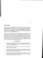
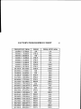
FACTORY PROGRAMMED MODE
The Factory ProgrammedMode Chart lists the entire frequencyrange of the
receiver in segments. Each frequency segmentis listed with the mode and
frequencystepthat the segmenthas beenprogrammedto operateon. This factory
programminghas beenestablishedfor thosemodesand frequencycombinations
wbich are most commonon a world-widebasis.You will find that you will wish to
changesomeof the modesand frequencystepsfor certainfrequenciesin your area.
Referto the FactoryProgrammedChart on the next page.
42
SPECIFICATIONS
GENERAL
FrequencyRanges:
25.0 - 999.95MHz (minimum 5 kHz steps)
ModulationType:
A3 (AM) / F3 (FM) wide or narrow
ProgrammableFreq. Steps:
5.0,10.0,12.5,20.0,25.0,
50.0,or 100 kHz
ScanningSpeed:
35-Ch/ Secin VFO mode
25-Ch / Secin MEMO mode
MemoryChannels:
200 Channels(10 groupsof20-Ch ea)
AntennaImpedance:
50 O (BNC and "N" antenna connectors)
FrequencyStability:
+ 3 ppm (parts per million)
TemperatureRange:
32 to722 "F (0 to +50 "C)
PowerSource:
13.5 VDC +I07o,negativeground
PowerConsumption:
1.5 Amps (maximum)
Lithium Battery:
Type CR2032/l (3V) memory back-up
Seeyour AuthorizedShinwa Dealer
for replacement.
Size:
7.0(W x 1.97(H) x 5.9 (D) in
178 (W) x 50 (H) x 150 (D) mm
DIN standard for vehicle applications
Weight:
3.09lbs(1.4Xg;
43
RECEIVER
ReceivingCircuitry:
Tliple-ConversionSuper Heterodyne
IntermediateFrequencies:
1st. IF 999.5MHz 10.5MHz
2nd IF 45MHz
(FM-W)
3rd IF 10.7MHz
(FM-N, AM)
455 kHz
ReceivingSensitivity :
FM-N below-4 dbp (1zdb SINAD @150.1MHz)
FM-W below12dbu(12dbSINAD @80.1MHz)
AM
belowa dbp (12dbS/N @120.5MHz)
SquelchSensitivity:
FM-N below-5 dbtr(150MHz Band)
AM
below-5 dbp (150MHz Band)
External Speaker Jack:
Over 1 Watt to a speakerjack (3.5mm) for the
optional ZPIZ| external 8C)speaker
EarphoneJack:
Optional ZPI0D earphone(30 -600f))
SPECIFICATI ONS SUBJE CT TO CHANGE WITH OUTN OTICE OR OBLIGATION.
a
a
o
a
a
a
a
a
a
a
a
a
a
a
a
a
SROOTQIIICK REFERENCE CIIART
FUNCTION
OPER.ATION
MODE
REMARKS
ENTER
AFITEQ.
II{TO THE
vFo
PRESS'EI{T.'
ENTERTHE FREQ.
PRNSS'ENT'
'vF(y'
SCANNING NOT
ITTHEN
AVAILABLE
ENTERINGA
C}IANGE TIIE
FUNCTION OF
A PREVIOUSLY
ENTERED FREQ.
PRESS'MODE'',
"STEP" OR"ANT'
TTIEN CIIANGE
FUNCTION
ENTERA FREQ
INTOA
MEMORY'MEM(Y'
CIIANNEL
SELECT THE FREQ.,
PRESS'1w"
ENTERMEM CH f,
PRESS'ENT'
r-'!
Z
-'l
.
F{
t.
F
RECALLINGA
}IEMORY
CIIANNEL WIIEN
IN'\TFO''MODE
PRESS'V/trtr"'EIVf"
ENTERMEM CH #, &
PRESS'ENT': OR
'ENf'& "n "OR"V"
RECALLINGA
MEMORY
CIIANNEL WIIEN
IN'MEMO''MODE
PRESS'ENT'
ENTERMEM CII #, &
PRESS'EIYT'; OR
'EIVT'&,'n,' OR"V',
TO SCAN
PRESS'SCAIY"
PRESS" A ''
OR
PRESSII V I'
7t\
z
hl
2
a
a
a
a
I
o
t
o
a
a
a
a
a
a
a
a
a
rREQ.
CTIANGE TIIE SCAN
FUNCTION OF THE
RTSTIME SCAN
MODE
PRESS'SCAN.C"
TO SELECT'CAR"
'AUD" OR'"TIM'AS
ASCANMODE
SETTING TIIE
"olv'oR"oFTi
TIMER
F'UNCTION
PRESS TIMER
"olroR'l)FF'
ENTER TIME,
PRESS'El{r'
'MODE""
"sTEP"
OR
''ANT'
'MEMC/'
OR
NOT POSSIBIJ
ftIHEN TIIE "1" IS
DISPLAYED
FUNCTION IS
POSSIBLE WTIEN
TTIE "o" IS
FI-ASHING
POSSIBLE IF
'\rFcv'
IIQIDISPI-AYED
'MEMO'
"a "
OR
ilV
PRESS'SCAN'
AGAINTO STOP
THIS MODE
rt
"cAR",
''AIID"
OR
lrl]fMlI
POSSIBLE IF
TTfE "a" IS
NOTDISPI"AYED
TTIIS FUNCTION
CANBE CIIANGED
WIIIIJ
INArrfY
MODE
"o"
MAXIMUMTIME IS
99 HRS & s9IVIIN
FROM THE
PRESENT TIME
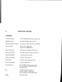
Shinwa Communications
of America. Inc.
P-O.Box264O7
Oklahoma City, Ok 73126
u.s-4,.
Tel:1 (8OO)6274722
Shinwa Communications
FAX:1 (aOO)769-1722
of Canada. Inc.
P.O. Box 24625 stc
Vancotrver, B.C., Canad a Y 5T 4E2
Tel:1 (6o4) 876-OOOG
Shinwa Communications
FAX: I (6,04) 8764288
of Latin America
6512 Six Forks Rd,, Suite 4OlB
ft^aleigh, N.C. 27615
u.si..
FAX: I (919) 846-2124
Tel:1 (919) a46-7751
Shinwa Communications
'Iel: +46 (O8) 643-7510
of Europe AB
FAX: +46 (O8) 643-4003
Shinwa Tsushirrki Co.. Ltd.
4 -C I{OMfl, SU (; INAMII{U, TOI(YO, .JAPAN
12-2 IIAMADAY.AMA
'r'FlL (o3)
313-1211
FAX: (03) 3313-1;i8
cl;Tlr,E: RELrArlr,ESlrrNcoM
Tor{yo
TULI'X: J27 432 SINWACOM
*ACISB}ES
YL\CHIOJL
'-TOCHIGI:
1216 K u-NUGIDA-CHO,
l}]L: t}426-61-5161
262-i9 SIIII}AIIIARUNO
'IEL: O?85-44-5711
I{ACHIO.]I
CIT\'-'I'OKYO
KOKL,IBLT{JI-CFIO
SIIIMO'IS
UGA-ct.j N