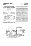
1
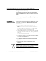
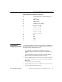
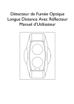
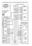
Release
Notes
Access System 2000
Red Zone Encryption Management
System (REMS)
Release Notes
IMPORTANT
!
TIP
Read this Release Notes document before you read the REMS user
manual.
This Release Notes provides corrected information for the Red Zone
Encryption Management System User Manual, Chapter 6, Configuring
and starting REMS, in the section, “Configuring REMS using the
thumbwheel switches. Use the following information instead of section
mentioned above.
Verilink suggests you manually cross out that section in the A(1) rev of
the REMS user manual, up to but not including the section, “Interpreting
the LED indicators, page 6-5.”)
Configuring REMS using the thumbwheel switch
The operator uses the EXE (execute) and FUNCTION thumbwheel
switches on the NCC 2020 modules to configure REMS. There are
thumbwheel switches in both the FBR and the BRC. You must configure
the FBR and the BRC separately, as if they were two separate AS2000
nodes.
Figur e1, NCC Thumbwheel Switches shows the top section of the master
NCC 2020 front panel.
Part Number 883-101598-001-A
Red Zone Encryption Management System (REMS) Release Notes
1
Access System 2000 Red Zone Encryption Management System (REMS) Release Notes
CAUTION
!
Figure 1
Do not attempt to use AM2000 or ASCIITerminal Interface (ATI) to
configure REMS. (There are some exceptions, which are noted.) Use only
the thumbwheel interface. If you accidentally change configuration using
the AM2000 or theATI, reconfigure the system using the thumbwhee
interface. Do not use other thumbwheel commands that you may find in
AS2000 manuals. Unspecified results may ensue.
NCC Thumbwheel Switche
NCC
2020
First digit o
command.
(TENs Value)
EXE
Second digit of
command.
(ONEs Value)
X
Using the
thumbwheel
switches (overview)
X
FUNCTION
Push the buttons on
this side to increment
the digit values.
Press this button twice
within 1 second to
execute the command.
Push the buttons on
this side to decrement
the digit values.
The system must be powered up before you use the thumbwheel switch
interface. The thumbwheel switch interface is enabled by default. You can
log into Access Manager 2000 (AM2000) to verify that the thumbwheel
switches are enabled.
Before entering thumbwheel commands, you must address the
appropriate FBR or BRC NCC 2020 by entering its slot address number
into the thumbwheel switches. Slot addresses numbers are two-digit
numbers that range from 01 to 30. The NCC is typically in slot 01.
Configuring the system using the thumbwheel switches is a two-step
process. The operator enters a command by setting the FUNCTION
thumbwheel switches to the corresponding command number (address).
The operator then presses the EXE button twice (in one second).
2
Red Zone Encryption Management System (REMS) Release Notes
Part Number 883-101598-001-A
Configuring REMS using the thumbwheel switch
Each command consists of two digits. The switch nearest to the EXE
push-button sets the first digit of each command and has a TENs
arithmetic value. The other switch sets the second digit of the command
and has a ONEs value.
Accessing the NCC
2020 using the
thumbwheel
switches
Plug-in module slot addresses range from 01 to 30. Slot numbers are
assigned to dual-line and multi-lined shelves from left to right, continuing
from one shelf to another. See Figure 2-2 in the Red Zone Encryption
Management System User Manual. The figure is titled, “Front Panel
View Concept Drawing, Dual-line and Multiline Shelf Rack
Configurations.” (For more information, see the AS2000 manuals
referred to in the preface of the REMS user manual.)
Every module in an Access System 2000 node has a unique two-digit
location number, or address. In a node with two multiline and two dualline shelves, the module addresses for thumbwheel switch access are 01
to 13 in the first multiline shelf and 14 to 26 in the second multiline shelf.
The module addresses in the dual-line shelves are 27 and 28 in the first
shelf, and 29 and 30 in the second shelf.
If the node has only dual-line shelves, the module addresses are 01 and 02
in the first shelf, and 03 and 04 in the second shelf.
NOTE
You must configure the FBR and the BRC separately, as if they were two
separate AS2000 nodes.
Accessing modules
To access the desired NCC, enter its address in the thumbwheel switches
and press the EXE button twice within one second. See Figure1, NCC
Thumbwheel Switches. The STAT LED of the module flashes green,
indicating that it is accessed and waiting for your next command.
Once an NCC has been accessed, you have 60 seconds to enter another
thumbwheel switch command. If no command is entered within this time
period, the accessed module returns to the idle state and its STAT LED
goes out.
Part Number 883-101598-001-A
Red Zone Encryption Management System (REMS) Release Notes
3
Access System 2000 Red Zone Encryption Management System (REMS) Release Notes
Clearing an incorrect address entry
If you accidentally access the wrong module, enter command 00 and
rapidly press the EXE button twice. This releases the currently accessed
module.
If you enter command 00 while a QRSS test signal is applied to an NCC,
or while a loopback is in progress, nothing happens. The loopbacks must
be deactivated first.
Procedure for
configuring the FBR
Use the following procedure for configuring the FBR NCC 2020. (For list
of commands, see the subsection, FBR Thumbwheel Configuration
Commands, below.)
1. Access the FBR by entering its location address into its the
thumbwheel switches (located on the front panel of the FBR NCC
2020).
The STATUS light on the front panel of the NCC begins flashing
Green. (You have 60 seconds to perform the next step.)
2. Using the FBR thumbwheels (located on the front panel of the FBR
NCC 2020), set the FBR to 40. This is the “canned” (preconfigured)
FBR option.
The NCC STATUS light stops flashing.
3. As appropriate, configure one of the FBRs in the circuit to be Master
(64) and the other end, Remote (65).
4. As, appropriate, configure the access port to D4 or ESF framing.
(You can also use the ASCII Terminal Interface (ATI) to set these
parameters.)
5. Select the line code.(You can also use the ATI to set these
parameters.)
IMPORTANT
!
4
If you reset the thumbwheel switches to 40 at any time after performing
the above procedure, all settings are reset to the defaults. You must then
reenter the commands that make the configuration unique.
Red Zone Encryption Management System (REMS) Release Notes
Part Number 883-101598-001-A
Configuring REMS using the thumbwheel switch
FBR Thumbwheel Configuration Commands
Procedure for
configuring the BRC
40
Canned FBR Option 1 (Remote REMS is the
default.)
64
FBR is Master
65
FBR is Remote
68
Disable Re-sync (Default)
69
Re-sync= 2 seconds
70
Re-sync= 4 seconds
71
Re-sync= 6 seconds
72
Re-sync= 8 seconds
73
Re-sync= 10 seconds
80
D4
81
ESF
82
AMI
83
B8ZS
Using the BRC thumbwheels (located on the front panel of the BRC NCC
2020), select the BRC timing mode for each BRC in the circuit. Refer to
the subsection, BRC Timing Options, below.
1. Access the BRC by entering its location address into its the
thumbwheel switches (located on the front panel of the BRC NCC
2020).
The STATUS light on the front panel of the NCC begins flashing
Green. (You have 60 seconds to perform the next step.)
2. Using the FBR thumbwheels (located on the front panel of the FBR
NCC 2020), set the FBR to 40. This is the “canned” (preconfigured)
FBR option.
The NCC STATUS light stops flashing.
3. Select the BRC timing mode for each BRC in the circuit. Refer to the
subsection, BRC Timing Options, below.
Part Number 883-101598-001-A
Red Zone Encryption Management System (REMS) Release Notes
5
Access System 2000 Red Zone Encryption Management System (REMS) Release Notes
BRC Timing Options
Select one of the settings 40 through 43, which are canned programs.
Then select from 50 through 63 as appropriate.
40
(Canned program) Internal timing, generate
PRMs (Performance Report Messages)
41
(Canned program) Network loop timing,
generate PRMs
42
(Canned program) Internal timing, no PRMs
43
(Canned program) Network loop timing, no
PRMs
50
Internal timing
51
Network loop timing
52
Equipment timing
53
External timing RS442
54
External timing TTL
62
Disable transmit of BRC message
63
Enable transmit of BRC message
Correct the error in Troubleshooting chapte
On page 8-5 of the rev A(1), Red Zone Encryption Management System
User Manual, delete step 5, b of the eight-step procedure at the top of the
page. Step 5, b does not apply.
Correct spelling of T-Berd and FireBerd
On page 8-4, in the first paragraph under the Section, “Troubleshooting
using a testset and loopback,” the correct spelling of the example testsets
should be: “...FIREBERD, T-BERD, or Verilink’s TS2000.”
6
Red Zone Encryption Management System (REMS) Release Notes
Part Number 883-101598-001-A