1
United States Patent {191
I} 1}
4,315,523
Mahawili et a1.
[45]
Feb. 16, 1982
[54} ELECTRONICALLY CONTROLLED FLOW
METER AND FLOW CONTROL SYSTEM
[75] Inventors: Imad Mahawili, Sunnyvale; Timothy
J. Boyle, Cupertino, both of Calif.
American Flow Systems, Inc,
Sunnyvale, Calif.
[21] Appl. No.: 127,918
[52]
coir 3/20
U.S.Cl. ............................... ..137/486; 137/4875;
73/269
{55} Field ofSearch
137/486, 487.5; 73/269,
73/270,271
References Cited
U.S. PATENT DOCUMENTS
287,587 10/1883
Spooner .............................. .. 73/270
3,181,360 5/1965 Hederborst
73/270
3,906,793
9/1975
Wurzbacher .
4,067,239
1/1978
Arvisenet
73/269
4,134,423
l/l979
Mayer ............................... .. 137/486
... ...
. . . ..
instantaneous position of the diaphragm. A novel elec
more sensing devices to provide measures of the flow
Mar. 6, 1980
[56]
in a ?ow control system. One or more sensing devices
are mounted on the walls of the chamber to sense the
tronic control circuit processes the data from the one or
[73] Assignee:
{22] Filed:
{51] Int. c1.3
drical). The chamber comprises part of the ?ow meter
73/270
Primary Examiner—-Alan Cohan
Attorney, Agent, or Firm-Alan H. MacPherson; Steven
F. Caserza
[57]
ABSTRACT
A novel, low-friction, low-inertia ?exible diaphragm
rate during the displacement of the diaphragm along the
cylinder. Signals are generated by the electronic control
circuitry for switching a pair of three-way valves (one
valve comprising the input valve and the other valve
comprising the output valve) such that during one'half
ot'a cycle the intput valve transfers ?uid into the cylin
der on one side of the diaphragm and, during the other
half of the cycle, transfers ?uid into the cylinder on the
other side of the diaphragm. The output valve is
switched synchronously with the input valve to trans
mit ?uid from the other side or one side of the dia
phragm to the output valve.
The electronic control system includes means for ampli
tying the output signals from the one or more sensing
devices (“sensors") to provide one or more signals rep
resenting the position of the diaphragm as a function of
time, means for converting the output signals from these
ampli?ers to digital form, and computation means for
operating on the digitized output signals from the sens
ing devices to provide control signals for controlling a
second input valve thereby to control the ?ow rate of
the ?uid being metered to within a desired range.
containing a magnet formed as an integral part of the
diaphragm is mounted in a chamber (preferably cylin
11 Claims, 16 Drawing Figures
/STEPPING MOTOR
SENSOR
’
/
@- —
6e
DIAPHRAGM
FLUID)
OUT
Emggr~~llllllili
WHEEL
° 7)
HOUSING
5
SET POINT
)
‘'7
SWAY/
VALVE I
\4
L
menu
I/DlSPLAY
d)
\m
cgmglcarcmomc’
POWER
GNTROL UNIT SUPPLY
FLUID IN
53
US. Patent
Feb. 16, 1982
4,315,523
Sheet l of 10
FIG. |
ELECTRONIC‘
NoNnoN
AmsPLAY
IN"
ELEcTmcAE
MAGNET
E SIGNALWSENSGR
1%
'“ZA
’
BELLowmJPRESSURE
UvLBEEwNm
BALANCE
Baum
our NNL;
MAGNET
sENsOREI‘;
NAcNETs’:
'
.
~
PORT
FIG.20
RAG“
FLUID/'
‘N DIAPHRAGH
HOUSANG
WP
U.S. Patent
Feb. 16, 1982
Sheet 2 of 10
4,315,523
/STEPPING MOTOR
C
@MUCILAU InuF=|
NA
Hmm./E0U3 Q."Na \)
_
/
UVl. 71 .10.mw.3F_I L_AIV Ia. ” AImVR
F I G. 3
FLUID
m
33 MOTOR-DRIVEN
comm VALVE
VALVE
lNLvl
.nPUlSwWsH?wmWENHWUHEm.ADB.nL‘vl Tl.
c. "
US. Patent
PRU(EOVILPNRTSEAG,)
Feb. 16, 1982
Sheet 4 of 10
4,315,523
4000
5800
3600
3400
3200
5000
2800
2600
2400
2200
2000
I800
I600‘
I400
I200
I000
800
600
400
200
[4 l3 l2 H l0 9 8 7 6 5 4 3 2
l MAGNET AT
:“WALL
VOLUME
DISPLACEMENLCM
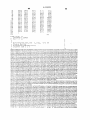
FIG, 6
3
LOWER
REVERSAL
‘256m
I 0
US Patent
Feb. 16, 1982
Sheet 7 of 10
FIG. 9
mum
I001»
4,315,523
gm92
1
\
*
Tom-i220
"m0 OUT
RAcRERc
FLUX
cRARRELR
swRcR
,
>
5"
633552
—
90
IOOK ms
ZENERT_91
___
1
T
93
pa
0
rDRlVER
?zi'iv?c
w “i
_
_ n u
.0
_
_ _
M20
D‘ STEPER
i_ 2i
_X
no:
:03
,,
TTLI’o , w
MOTOR
DRIVER
moms:
W!
CIRCUIT
STEPER
mos)
STEPER
MOTOR
wmumcz
DRWER
MOTOR
CiRCUlT
wmnmcs
OUTPUT
P'bR'T 2
DRIVER
R3
STEPER
"—
cmoun
gm
,
CIRCUIT
' |N4I|4
‘! ‘36
mob
94
°'
?
MOTOR
mod}
/l00e
RRRRIRGR
"4
DRWER
cmcun
50L N |
E 0 D‘
'
MOTOR &SOLENOID
oRwiRclRcun'“ '00’
FIG. :0
,
354353
s:
——-1
=-
50mm“?
? s2
US. Patent
Feb. 16, 1982
Sheet 9 of 10
4,315,523
EM:
PONEPOWER on
ASSEMBLY PROCEBURE
JRESET & m srm
INITIAHZE LINES Ill-H8
UNE l2!
LINE I25 ‘
cm
REVCHK
‘LINE swncu
'49 SOLENOIDS
"0
N0
l
0 LL
came
DELAY
1
CALLNEW VLV
ADJUST
CBMPUTE
‘ lgg?gl
"5“ m1”.
gi??isusze
wW
AUTO RANGE
'
Lmalzs
7
OR :35
CALL
NEW VLV
ADJUST
VALVE
BEGIN A gg?ég
LINE
END OF
new SAMPLE
'45
SAMPLE
I
FlG. l2
L__
US. Patent
Feb. 16, 1982
Sheet 10 of 10
4,315,523
20° SEC
uPP§RIONDIE
200a
INNER
,
A glglNs
WNW"
ELASTONER
RAW
MATERIAL
2M
/ OUTER
’
--
ELASTONER\
[mun
gigc 200C 2'2
FIG. l3
1
4,315,523
2
placement of the diaphragm along the cylinder. Signals
are generated by the electronic control circuitry for
switching a pair of three-way valves (one valve com
prising the input valve and the other valve comprising
the output valve) such that during one-half of‘ a cycle
ELECTRONICALLY CONTROLLED FLOW
METER AND FLOW CONTROL SYSTEM
5
1. Field of the Invention
the input valve transfers ?uid into the cylinder on one
This invention relates to an electronic flow control
side of the diaphragm and, during the other half of the
cycle, transfers ?uid into the cylinder on the other side
of the diaphragm. The output valve is switched syn
chronously with the input valve to transmit fluid from
system using an electronically-controlled positive dis
placement ?ow meter.
2. Prior Art
Positive displacement ?ow meters are well known.
Thus British Pat. No. 1,051,710 published Dec. 21, 1966,
the other side or one side of the diaphragm to the output
valve.
The electronic control system includes means for
amplifying the output signals from the one or more
sensing devices ("sensors“) to provide one or more
discloses a positive displacement flow meter utilizing a
cylinder wherein a reciprocating piston is controlled to
move from one end to the other of the cylinder in re
sponse to the alternate passage of the fluid whose flow
is being measured into the cylinder at one or the other
end of the piston. As fluid under pressure enters one end
signals representing the position of the diaphragm as a
function of time, means for converting the output sig
of the cylinder via an inlet pipe, the piston is pushed
nais from these amplifiers to digital form, and computa
along the cylinder and the ?uid which entered the cyiv
tion means for operating on the digitized output signals
inder at the other end of the piston as a result of the 2%) from the sensing devices to provide control signals for
controlling a second input valve thereby to control the
previous stroke is forced into the outlet pipe. Valves in
flow rate of the ?uid being metered to within a desired
a well known arrangement allow ?uid to alternately
enter one end of the cylinder and be withdrawn from
range.
the other end of the cylinder and vice versa.
As a feature of the invention, an output ?ow rate is
Other positive displacement flow meters are shown in 25 not determined unless and until the diaphragm has trav
elect a selected distance or until a maximum time has
US. Pat. No. 2,772,664 issued Dec. 4, 1956 to Jones, et.
elapsed, thereby to ensure that a minimum volume of
al., LLS. Pat. No. 3,181,360 issued May 4, 1965 to Heder
horst, and U.S. Pat. No. 3,657,925 issued Apr. 25, l§72
to Gross. The ‘710, '664, ‘925 and ’360 patents all dis
fluid has entered the positive displacement ?ow meter
portion of the control system and displaced the dia
close reciprocating pistons as the positive displacement
member. However, the ‘360 patent discloses in addition,
phragm at least a selected amount. By dividing this
displacement by the time over which it occurs, the
the use of a flexible diaphragm 18 to seal a rigid piston
16 (FIG. 1 of the ’360 patent), which travels between
two chambers in a cylinder, to the cylinder wall. As one
volumetric ?ow rate is obtained.
DESCRIPTION OF THE DRAWINGS
chamber is ?lled with gas or ?uid, a like amount of gas 35
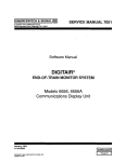
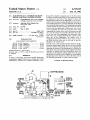
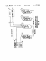
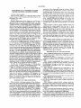
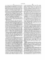
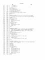
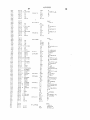
FIG. 1 illustrates schematically the chamber in which
is located the positive displacement diaphragm used for
or ?uid is expelled from the other chamber. Reversal of
the chambers in which gas is inserted and from which
the gas is removed causes the diaphragm to reciprocate
measuring flow rate.
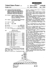
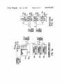
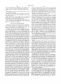
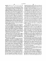
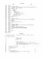
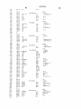
FIGS. 20 and 23) show diaphragms connected to the
chamber by bellows and an O-ring type seal, respec
back and forth across the chamber. The number of
strokes of the piston-diaphragm combination (with the 49 tively.
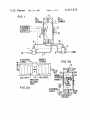
FIG. 3 shows schematically the connection of the
diaphragm made of Te?on or rubber), is representative
of the volume of gas passing through the meter.
sensing element on the end of the chamber containing
the diaphragm through an electronic controller to an
US. Pat. No. 3,974,825 issued Aug. 17, 1976 discloses
electronically controlled valve for maintaining the
a pump using a ?exible, pneumatically-driven dia‘
45 proper fluid flow.
phragm for pumping blood in an arti?cial heart.
FIG. 4 shows schematically the relationship of the
Each of the above structures has certain disadvan
tages. A piston introduces inertia and friction into the
diaphragm, ?ow chamber, sensing elements, the ini
?ow system thereby affecting the flow to be measured.
crocomputer used to compute the control signals used
to control the ?uid ?ow rate, the fluid control valve and
Moreover, the fluid whose flow is being measured often
leaks past the piston. In addition, the frequency re 50 the structure for controlling the ?uid flow into the ?ow
sponse of the system is limited by the inertia of the
chamber.
H6. 5:: shows the reed-switch ?ow reversal control
circuit useful with this invention.
piston. For accurate ?ow control, a low inertia, low
friction, accurate flow meter is required as an essential
part of the control system.
SUMMARY OF THE INVENTION
FIG. 5b shows a circuit useful with the circuit of
55
FIG. 50 for producing an output voltage proportional
to flow rate.
This invention overcomes certain of the disadvan
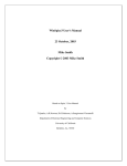
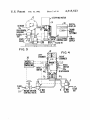
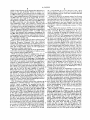
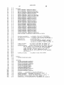
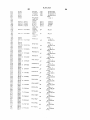
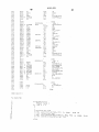
FIG. 6 shows a typical output voltage versus dis~
placement curve used with this invention for calibrating
the output voltage from a sensing element on the end of
In accordance with this invention, a novel, low-friction,
low-inertia ?exible diaphragm containing a magnet 60 the cylinder to the position of the diaphragm within the
formed as an integral part of the diaphragm is mounted
cylinder.
in a chamber (prei'errably cylindrical). The chamber
FIG. 7 shows the microcomputer based flow control
comprises part of the flow meter in a flow control sys
ler structure connected to the sensing element on the
tages of the prior art positive displacement flow meters.
tem. One or more sensing devices are mounted on the
end of the chamber containing the diaphragm.
walls of the chamber to sense the instantaneous position 65
FIG. 8 shows the relationship of the various circuit
boards used to process the signals from the sensor and
to control the settings of the three‘way ?ow valves 1
and 2 (FIGS. I and 7) which allow the ?uid to pass into
of the diaphragm. A novel electronic control circuit
processes the data from the one or more sensing devices
to provide measures of the ?ow rate during the dis
3
4,315,523
one or the other of the chambers in the cylinder. and
which control the setting of the ?uid control valve.
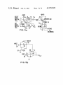
FIG. 9 shows a sensor circuit useful with this inven
tion.
FIG. 10 shows the motor and solenoid driver circuits
used with this invention.
FIGS. 11a and 11b show schematically the thumb
wheel digit input circuit and the display circuits used
4
position of magnet 5. Since each sensor's output voltage
is uniquely related to the position ofthe diaphragm, by
measuring time independently. the sensor output volt
age and thus the diaphragm position is determined as a
function of time which allows the ?ow rate to be calcu
lated given a calibration curve of volume versus dia
phragm position (as shown in FIG. 6).
The use of a ?exible diaphragm as part of a ?uid
with this invention;
meter is based on our discovery that‘ contrary to expec
FIG. 12 shows the logic diagram for the computer 0 tation, the diaphragm position as a function of volume
program used in the microcomputer shown in FIG. 7 as
of fluid in each chamber is predictable and repeatable
part of the structure of this invention; and
each cycle despite the fact that the diaphragm is ?exible
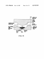
FIG. 13 shows schematically the method and struc
and “loose" (i.e., the diaphragm is designed to interfere
ture for fabricating the diaphragm with an enclosed
minimally with the fluid ?ow). Thus, diaphragm 4
magnet used with this invention.
serves to separate the left chamber 12b from the right
chamber 12a while supporting magnet 5. the position of
DETAILED DESCRIPTION
which is used to measure the fluid flow rate. The cali
While this invention will be described in conjunction
bration ofthe position of magnet 5 to the output signals
with speci?c components in the electronic control cir—
from sensors 6a and 6b is essential to the proper opera
cuitry, this description is exemplary only and is not 20 tion of this system. As is apparent from FIG. 1, dia
intended to limit the scope of the invention.
phragm 4 can easily be replaced should it wear out by
Turning now to FIG. 1. a flow chamber 12 contain
ing a right chamber 120 and a left chamber 121) sepa
rated by diaphragm 4 is shown schematically. Dia
phragm 4 has mounted on its center as an integral part
thereofa magnet 5. Magnet 5 is completely coated with
the material of which diaphragm 4 is constructed to
protect magnet 5 from the ?uid (possibly corrosive)
being metered. On the left face of chamber 12 is a sensor
6b and on the right end of chamber 12 is a second sensor
6a. If desired, only one sensor (either 60 or 61;) can be
used. While shown as reed switches, preferably, these
sensors comprise Hall effect devices of the type known
as LOHET (for "linear output, Hall-effect transducer")
separating the two halves of cylinder 12, removing the
old diaphragm and inserting a new diaphragm. Typi
cally, to ensure a leakproof connection, diaphragm 4
has two “O-rings,” an inner "O-ring” 210 and an outer
“O-ring" 211 as shown in FIG. 13 (which shows the die
used to fabricate the diaphragm).
It is apparent from the above description that the
position of diaphragm 4 as a function of time is directly
proportional to the volumetric ?ow rate of the fluid. By
knowing the temperature and the pressure of the ?uid
the mass ?ow rate can be determined in a well known
manner.
When sensors 60 and 6b comprise reed switches, the
sensors such as described in more detail in Electronic 35 output signals from these switches occur with a fre
Design 19, dated Sept. 27, 1979, on page 23. This article
is incorporated herein by reference. Other Hall effect
sensors can. of course, also be used with this invention.
The input ?ow is transmitted through three-way
valve 1 (shown schematically) arranged to allow the
?ow to pass into line 9 connected directly to left cham
ber 12!). The entry of fluid into left chamber 121) dis
places diaphragm 4 to the right thereby expelling ?uid
in the right chamber 120 through line 10. Three-way
quency directly proportional to the flow rate and are
used directly to actuate electronic circuitry for both
valve actuation and feedback or other ?uid control
purposes. On the other hand, when the output sensors
60 and 6b are Hall effect devices, a continuous output
signal is generated from each of these sensors. This
output signal is related to the flow rate. By knowing the
calibration curve of output signal level versus displace
ment of the diaphragm 4 and magnet 5, the volumetric
outlet valve 2 is. in this mode, adjusted to allow the ?uid 45 flow rate can be calculated continuously as a function of
?owing from line 10 to pass directly into the output line.
the output signals from sensors 6a and 6b.
During the entry of ?uid into left chamber 12b. dia
Diaphragm 4 is preferably made of an elastomeric
phragm 4 and magnet 5 move to the right toward Hall
material (viton is preferred but neoprene, silicon rubber
effect sensor 60. The output signal from Hall effect
and butyl rubber can also be used, as appropriate) which
sensor 60 is a function of the position of magnet 5,
is suitable for use for temperatures up to 150° C. (180° C.
which in turn, is proportional as a function of time, to
for viton). For higher temperatures metal bellows can
the rate of ?uid ?ow through line 9 into left chamber
be used in place of the elastomeric diaphragm. The
12b. As magnet 5 moves closer to sensor 60 due to the
choice of the diaphragm 4 material depends on the
displacement ofdiaphragm 4 to the right, the Hall effect
particular fluid that is to be used, and the preferred
sensor 6:: produces an output signal uniquely related to 55 operating temperatures. The differential pressure across
the position of magnet 5. This position as a function of
the diaphragm is small in comparison to the working
time is a function of the flow rate. Sensor 60 produces
fluid pressures. Preferably this pressure difference is
an output signal which is monitored in a manner to be
negligible. Viton is appropriate for temperatures be
described later by the electronic control circuits. As
magnet 5 reaches its rightmost position, a control signal
is generated switching valves 1 and 2 such that the input
gas now ?ows through line 7 into rightmost chamber
120 while the ?uid in leftmost chamber 12b is expelled
from this chamber through line 8 and outlet valve 2.
Consequently, diaphragm 4 is forced to the left and 65
tween —40° C. and 180° C. and pressures between vae~
uum and 300 atmospheres.
The diaphragm with encapsulated magnet is made by
magnet 5 now travels away from Hall effect sensor 60
a compression or transfer molding process. In this pro
cess (illustrated in FIG. 13), a metal die 200 containing
upper section 2000 and lower section 20017, is fabricated
to the exact dimensions of the diaphragm. Die section
2001) includes a central cavity 20th: to house the magnet
and toward Hall effect sensor 6b. The output voltage
from Hall effect sensor 6b is also uniquely related to the
of the elastomer material 213 having the same or
212 (corresponding to magnet 4 in FIG. 1). A thin disc
5
4,315,523
6
slightly larger diameter as the magnet disc 212 (approxi
mately é inch and preferably formed of Alnico 8 or
Cemarium cobalt} is ?rst inserted into the magnet cav
ity 200C and the magnet 212 is placed on top of this thin
2b a conventional set of two three-way flow valves
(such as shown in FIG. 1) is used to first route the fluid
into one chamber and out of the other chamber and then
to reverse this pattern.
disc. A pre-weighcd amount of the elastomer raw mate
rial 214 is then put on top of the magnet 212, the mate
rial is heated to about 400° F. when Viton is the material
Contrary to the prior art meters using a free flowing
piston. wherein the fluid whose flow is being measured
can often leak from the left chamber to the right cham
and pressure is applied to it by the upper half 200a of the
ber and vice versa, this invention uses a flexible. low
die 200 to mold and cure the elastomer 214 to the de
inertia diaphragm to seal one chamber from the other
and thereby to prevent leakage while at the same time
providing a relatively instantaneous measure of fluid
sired diaphragm shape. The pressure is merely that
sufficient to achieve the desired result. The compression
is conducted at an elevated temperature whose magnie
tude depends on the particular elastomer and results in
elastomer material 214 and 213 assuming a substantially
uniform thickness (typically 0.015" to 0.020" when
Viton is the material) and consistency throughout the
die 200. This operation ensures complete encapsulation
of the magnet by the elastomer and excellent control of
the diaphragm thickness. A Viton diaphragm typically
has a durometer of ?fty (50).
flow rate.
FIG. 3 shows the structure of FIG. 1 (or the cham
bers of FIGS. 2a and 2b). in combination with an elec
tronic controller 30, a DC stepping motor 31, and a
clutch or coupling 32 joining the stepping motor to a
valve 33 (typically a needle ?ow valve) for controlling
the flow of fluid. The DC stepping motor 31 adjusts the
position of the valve 33 until the flow rate detected by
20 the meter corresponds to a flow rate setpoint input to
A particularly suitable valve for use as valves 1 and 2
the electronic controller 30. As will be shown later, the
electronic controller 30 preferably comprises a micro
processor controlled digital circuit with an analog-to
digital converter, a sampling circuit, buffer stores, mem
303 and 430 stainless steel with viton eiastomer for the 25 ory and selected input and display elements. The elec
seals and O-rings. Other valves are also appropriate
tronic controller 38 also controls the setting of the two
depending on design requirements.
three-way valves 1 and 2 to ensure that the fluid flow
The flow measurement by this device is reproducable
into the meter and from the meter is reversed at appro
well within one percent. Diaphragms or bellows can be
priate times to obtain maximum accuracy in the flow
(FIGS. 1 and 7) is the D30 three-way valve made by
Precision Dynamics Company. This valve switches
within about eight milliseconds and is fabricated out of
easily replaced before fatigue sets in.
30 measurements. The system provides accurate and re
FIGS. 20 and 21) show two con?gurations for the
diaphragm inside the cylinder. In FIG. 2a, a diaphragm
has a magnet mounted internally to it which is pro
der 12 is reversed when the diaphragm reaches its exv
tected by the material of the diaphragm. The diaphragm
treme position one way or the other. The flow rate can,
sponsive feedback (or feed forward if desired) control.
In the simplest form, the flow into one side of the cylin
is then connected and sealed to the ends of two bellows. 35 in this embodiment, be simply measured by the time it
Each bellows is capable of contracting or expanding in
takes for the diaphragm to travel between the two ex
response to lateral movement of the diaphragm in re
tremes. That is, the flow rate is equal to the volume
sponse to ?uid entry into one or the other chambers of
between the two extreme positions of the diaphragm 4
the cylinder. Thus when fluid enters the left chamber of
divided by the time taken by the diaphragm to travel
the cylinder, the diaphragm and the magnet move to the
between these two positions.
right and the fluid in the right chamber is expelled.
FIGS. 4 and 50 show an embodiment of this inven
When fluid enters the right chamber, the magnet and
tion using a reed switch to detect the maximum dis
the diaphragm move to the left expelling the ?uid in the
placement of the diaphragm adjacent each of the two
left chamber. A magnetic sensor mounted on the cylina
walls of the cylinder 12. The reed switch signal is trans
der detects the motion of the magnet and thereby pro 45 mitted to a microcomputer control 39 which then calcu
duces an output signal proportional to the position of
lates from the time taken for the two reed switches 46a
the diaphragm. Typically the bellows comprises either a
and 46b to be sequentially actuated, the measured ?ow
metal or polymer material and the diaphragm likewise
rate. This measured flow rate is compared to a reference
comprises a polymer or metal material.
flow rate set into memory and the difference is used to
FIG. 2b shows a different construction wherein the 59 set a control valve 33 to bring about the proper flow
diaphragm is attached between two portions of the
rate. Solenoids and solid state relays are also actuated
cylinder. Again, a magnet 5 is mounted on the dia
by the microcomputer control 30 to reverse the fluid
phragm 4 and coated with the diaphragm material
thereby to protect it from the fluid whose flow is being
?ow into cylinder 12 at the maximum displacement
points of the diaphragm 4.
measured. The entry of fluid to the left chamber 121:
FIG. 5a shows a circuit schematic of the structure
displaces diaphragm 4 and magnet 5 to the right as with
the structure of P16. 2a and similarly the entry of fluid
to the right chamber displaces the diaphragm 4 and
used to respond to the change in state of the reed
switches 46:: and 4651 due to the approach of magnet 5.
magnet 5 to the left, again as with the structure of FIG.
2a. The diaphragm is constructed such that its motion to
the right or left occurs with very little friction or resis
tive force. Thus the flow of the fluid is not disturbed by
the presence of the diaphragm. In addition, the weight
of the diaphragm is kept very low thereby minimizing
the inertia of the diaphragm. Magnetic sensors 6b and 6a
are mounted on the left and right walls of the cylinder
to detect the movement of the diaphragm-mounted
magnet 5 to or from a given wall. In both FIGS. 2a and
A flip flop comprising two 7400 NAND gates 31 and 42
has as one input signal to each of the NAND gates the
output signal representing the state of a given reed
switch. Thus normally, when reed switch 46:: is open,
the signal level on input lead 410 to NAND gate 41 is at
a high level corresponding to the 5 volt DC supply
voltage. The other input lead 411) is coupled to the
output lead did from the other NAND gate 42. The
output signal on lead 41a’ is normally high level for at
least one low level input signal. Thus, with the signal on
output lead 41c low level, the signal on input lead 42b is
7
4,315,523
8
low level and the signal on output lead 41d from gate 42
twelve bit converter such as is used with the Analog
is high level, thereby holding the output signal from
Devices RTI-I220 Data Acquisition Board 84 (FIGS. 7
and 8). The output signal from A-to-D converter 75
comprises a digital signal representing any one of 4,096
possible signal levels. Of course, by selecting an A-to-D
gate 41 at low level. When reed switch 46a is closed, the
input signal on lead 410 to NAND gate 41 goes low
thereby driving the output signal from NAND gate 41
to a high level. This high level output signal is transmit
ted to input lead 42b of NAND gate 42 and drives the
output signal from NAND gate 42 to a low level
thereby latching up the output of NAND gate 41 to a
high level. The high level output signal from NAND
gate 41 is amplified by ampli?er 43 and turns offtransis
tor Q10 (2N2904) thereby changing the current through
converter containing a different number of bits, a differ
ent level of accuracy can be obtained.
The output signal from A-to-D converter 75 is then
transmitted to input buffer 76e. Input buffer 76e buffers
the output signal from A-to-D converter 75 and holds
this information until a request for this information is
received from microcomputer 81. Microcomputer 81
a coil to close two relay control switches thereby acti
comprises a Mostek MK79612 CPU and Timer Board
which contains a CPU corresponding to the well
way valves 1 and 2 shown in FIG. 1 and thus to reverse 15 known Z80 microprocessor. The MK79612 is shown in
the ?ow. When diaphragm 4 arrives at the other side of
more detail in the Mostek publication entitled “MD
vating solenoids to change the settings ofthe two three
the cylinder 12, reed switch 46b closes thereby driving
the output signal from NAND gate 42 from low level
(corresponding to two high level input signals) to high
level thereby driving the output signal from NAND
gate 41 to low level. This low level output signal is also
ampli?ed and used to turn on transistor Q10 thereby
again activating a relay to reverse the two three-way
?ow valves 1 and 2 (FIG. 1) and thereby again to re
Series Microcomputer Modules, Operations Manual for
MDX-CPU l" and subtitled “Z80 Central Processor
Module MDX-CPU 1“, copyright 1978 by Mostek Cor
poration. This document is also incorporated herein by
reference. FIG. 8 shows the relationship of the Mostek
MK79612 to the remainder of the circuit, the compo
nents of which are also shown in more detail in FIG. 7.
The control logic 760, input buffer 76e, A-to-D con
25 verter 75 and analog switch 74 comprise the Analog
verse the ?uid ?ow.
FIG. 6 shows a typical curve of output signal from a
Devices RTI 1220 data acquisition board 84 (shown as
Hall effect device (such as sensor 6b or 60 in FIG. 2b)
such in FIG. 8).
versus position of the ?ow diaphragm 4. This curve is
substantially linear over short portions but gradually
The output latches 76b, 76c and 76d comprise the
Pro-Log 7601 TTL I/O board 83 also shown in FIG. 8.
?attens out as the diaphragm 4 moves away from the 30 The program memory of the microcomputer 81 com
Hall sensor. The slope of voltage versus position (i.e.,
prises the Mostek MK79604 Eprom/UART board 82
displacement) is negative such that the output voltage
shown as such in FIG. 8.
as a function of the distance of the diaphragm from the
The data bus interconnecting the CPU timer and the
sensor increases with decreasing distance of the dia
Eprom/UART portions of the structure to the Pro-Log
phragm from the sensor. Operation of the sensor in a 35 7601 TTL [/0 board and the Analog Devices RTI 1220
region of substantially steep slope gives greater sensitiv
data acquisition board comprises the STD bus, a stan
ity and accuracy to the measurement of the ?uid ?ow
dard bus used by Mostek and Pro-Log for interconnect
than does operation in a region of ?atter slope. As will
ing the components of a typical eight bit microcom
be discussed shortly, this feature is used to enhance the
puter system using an eight bit microprocessor (such as
accuracy of certain ?ow measurements.
the Z80). The operation of the STD bus is described, for
FIG. 7 discloses the preferred embodiment of this
example, in the Pro-Log publication copyrighted l979
invention using a microcomputer-controlled digital
entitled “Series 7000 STD Bus, Technical Manual.”
The operation of this bus is thus well know in the art
and will not be described in detail. The above cited
circuit to provide proper feedback signals to control the
?ow rate. The microcomputer 81 operates on an output
signal produced from the Hall effect sensor 6b mounted 45 Pro-Log technical manual is incorporated herein by
on the wall of the chamber 12 containing the ?exible
reference.
diaphragm 4 with magnet 5 formed as an integral part
Control logic 76a generates several sets of output
thereof.
signals. First this logic generates a set of signals for
FIG. 7 shows in block diagram form the electronic
controlling the setting of analog switch 74. These sig
control circuitry used to process the information pro 50 nals are transmitted on lead 740. Logic 760 is driven by
duced by the sensor 6b attached to chamber 12 contain
signals taken off the STD bus and generated by mi
ing the ?exible diaphragm 4 used to measure ?ow rates
crocomputer 81.
in accordance with the invention. The output signal
Output latch 76b (part of TTL I/O Board 83) gener
ates a signal to actuate driver circuit 79b which in turn
from Hall effect sensor46b is transmitted through sensor
interface circuit 73 to analog switch 74. Analog switch 55 produces signals which operate three-way valves 1 and
for selecting a particular signal path in response to digi
2. Driver circuit 79b is shown in more detail in FIG. 10
and will be described below.
tal input signals (input to switch 74 on lines 74a from
control logic 76a) for the purpose of passing a selected
driver circuits 7% which in turn drive stepper motor
74 comprises in one embodiment a well-known device
Additional signals from output latch 76b also actuate
signal from either a pressure transducer 720 and a tem 60 790. Stepper motor 79c controls the setting of control
perature transducer 72b (for the purpose for allowing
valve 79d which controls the ?ow rate though valves 1
and 2. Thus the output of latch 76b (derived from mi
information produced from the signal generated by
crocomputer 81) controls the setting of valve 79d in
sensor 6b attached to ?ow meter chamber 12) or from
response to the flow rate measured from the signals
65 produced by sensor 6b.
sensor interface circuit 73.
The reference signal used to determine the magnitude
The output signal from analog switch 74 is transmit
and direction of change in the position of valve 79d is
ted to an analog-to-digital converter 75 of well known
construction. Preferably, this converter comprises a
derived by comparing the signal representing the ?ow
the mass ?ow rate to be calculated from the volumetric
4,315,523
10
be driven such that the control valve 790‘ is either
opened or closed based upon the last flow rate reading
rate computed from the signals from sensor 65 with
another signal placed in input buffer 760 and derived
from the setting of thurnbwheel 77. The setting of
present in the microcomputer when compared to the
thumbwheel setting. Typically, the stepper motor is
thumbwheel 77 can be varied as desired by the operator
driven by a sequence of signals on input leads D6
thereby changing as desired the setting of control valve
7%. Basically, thurnbwheel 77 converts a setting visible
to the user to four binary-coded decimal digits (corre
sponding to 16 bits). These signals are held in input
buffer 760 and are used by microcomputer 81 to calcu
late the proper control signal to be transmitted through
output latch 76b to control the setting of valve 796.’
through D3 corresponding to hexadecimal 5, 9, 6, A.
Thus if the setting of the stepper motor corresponds to
a 9, then the hexadecimal encoded binary 6 transmitted
on input leads D0 through D3 will activate the stepper
motor to move one setting in the proper direction to
open. Should the stepper motor be instructed to close
rather than open, then a hexadecimal encoded 5 would
Output latch 76:! is con?gured to retain the output
signals from microcomputer 81 corresponding to the
be transmitted in binary form on leads Di) through D3.
in this latter case wherein the most signi?cant digit
corresponds to a zero, the second most signi?cant digit
corresponds to a one, the third most signi?cant digit
latest reading of the flow rate. The signals retained in
latch 76:! activate display 78 to display the latest value
of flow rate calculated by microcomputer 8!.
Structures corresponding to those shown in FIG. 7
corresponds to a zero and the fourth most signi?cant
are shown in FIG. 8‘ Those elements shown in block
diagram form in FIG. 8 function as described above in
connection with FIG. 7 and thus will not be described
digit corresponds to a one (corresponding to the signals
0101 on leads D3 through D0, respectively), then the
"l” on lead D0 will drive the output signal from in
in more detail here.
H68. 110 and 11b show in more detail the thumb
verter 101 to a low level thereby turning on transistor
wheel circuitry 110a through 11% and the display cir
cuitry 1140 through 11415 used with this invention. The
thumbwheel is capable of inputting four digits into the
circuit. Each digit circuit 110b, 1100 and 110:!’ comprises
a replica of the speci?c circuit 110a shown ?guratively
voltage pulses generated by changing the current
through winding W1 from burning out transistor Q1
for digit one. This circuit is of a type well known in the
arts and thus will not be described in detail except to say
that if the thumbwheel is set, for example, on a 7, the
switches within the thumbwheel corresponding to the
4, 2 and 1 level signals (connected to the 5 V supply
voltage through resistors 112b, 112c and 112d. respec
tively), are closed thereby to provide an output signal
Q1 and energizing winding W1. 'Diode D1 prevents
25
and resistors 102 and 103 comprise pull-up and base
drive resistors, respectively.
FIG. 9 shows the circuitry associated with the Hall
effect sensor 61:. The magnetic flux from the magnet 5
mounted within, and as an integral part of, diaphragm 4,
is converted to a voltage and ampli?ed to produce an
output signal. Hall-effect sensor 61; preferably corn~
prises part number 633552 made by Microswitch, inc,
a division of Honeywell. The output signal from micro
switch 90 is transmitted via twisted-pair cable 94 to
for the TTL input at a level corresponding to the com 35 Analog Devices data acquisition board 84 (FIGS. 7 and
plement of 7 (negative logic). Any other decimal digit
8). There this output signal activates the processor to
operate in a way previously described. Pull-down resis
tor 92 (100 ohms) is connected between the ?fteen volt
power supply in series with a 5.1 volt zener diode ill to
The display likewise comprises a four digit display.
Each display 114a, 114b, 114a and 114d comprises a 4-3 ground, Variable resistor 93 (100K) is connected across
the node between resistor 92 and diode 9i and ground.
well known decoder driver for taking a BCD input and
Resistor 93 is used to produce a bias offset for the other
converting it to a digital number ranging from 0 to 9.
from 0 to 9 is selected by closing the corresponding
switches to provide an output signal of the proper level.
Typically, each display comprises an HP 7304 display
lead in the twisted pair 94 transmitting the output pulse
from microswitch 90 to the data acquisition board 84.
of a type well known in the art.
FIG. 18 shows in more detail a typical drive circuit of 4-5 This bias offset comprises a way of compensating for
the fact that the curve of lies versus voltage for the
the type used to drive the stepper motor 79c and the
solenoid driven three-way valves 1 and 2 (the latter two
Hall-effect sensor does not pass through the origin. By
valves being used as described above to reverse the
adjusting the setting of variable resistor 93, the input
signal to the control circuitry is offset (i.e., zero ad
flow in chamber 12). The driver circuits are driven by
signals on input leads d0 through d5 derived from the 56 justed) to provide a signal within a desired range of
magnitude.
TTL [/0 card (FIGS. 7 and 8). The particular stepper
Operation of the above described structure is imple
motor windings to be energized depend upon the setting
mented by a software program. The Microl high-level
of the stepper motor (a record of which is recorded in
language version of this program is attached to this
the RAM memory of microcomputer 81) and the direc
tion in which it is desired to move the stepper motor. 55 application as Appendix A. This program uses the Mi~
crol Language which is described in the User’s Manual,
The stepper motor will move a standard distance (typi
cally (l/200)th of a revolution) once each step. A timer
in the microcomputer allows the generation of a new
step after a fixed time has elapsed. In the embodiment of
this invention, this time is 7.5 milliseconds. The timer on
the microcomputer board 81 interfaces with the mi
crocomputer central processing unit (CPU) via inter
rupts. The timer generates periodically signals which
Microl Language, dated Mar. 8, i979. This Manual is
incorporated herein by reference.
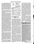
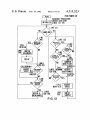
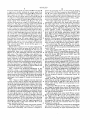
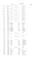
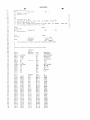
FIG. 12 illustrates the logic flow diagram of the com
puter program devised to operate microcomputer and
timer 81 (FIGS. 7 and 8) in accordance with this inven
tion. The computer program is designed to operate on
the output signals from sensors 6b as processed by the
data acquisition board 84 to determine flow rates. To do
activate an interrupt circuit within the CPU through an 65 this one of several algorithms is employed. In the pre
ferred mode of operation the flow rate is measured on a
interrupt pin. This signal then activates the CPU to
relatively continuous basis as a function of the displace
calculate the next setting for the stepper motor; that is
ment of diaphragm 4 across chamber 12 with time. This
the CPU determines whether the stepper motor should
are transmitted to the CPU on a separate line thereby to
11
4,315,523
preferred mode does not depend upon the reversal of
the direction of motion of diaphragm 4 to measure the
flow rate but does set an optimum reversal point for
changing the direction of motion of diaphragm 4 to
the valve.
In the above calculation, the program uses the sub
routine “GETFLO" to calculate the flow. Subroutine
“NEWVLV” corresponds to the control function
ensure that at least a minimum voltage difference from
sensor 6b as a function of the location ofdiaphragm 4 is
obtained in a given time. In the limit, the minimum
voltage difference per sample can be expanded to a
value corresponding to the reversal point of the dia
phragm. In this situation, the preferred mode reduces to
the second, reversal dependent mode. In essence, the
software emulates the operation of the reed switch
which generates the new valve position. “STPSIZ‘
corresponds on a one-to—one basis to the steps on a
valve. It then takes 7.5 milliseconds for the valve 79d to
make one step. The program does not sample while the
O
mode. but in addition provides an autoranging capahil~
ity (to be described later).
valve is opening or closing.
Once sampling is started, a sample is always obtained
before the direction of motion of diaphragm 4 is re
versed and before it is necessary to reverse the motion
of diaphragm 4. An important part of the system is the
calibration table calibrating the volumetric displace
The second mode of operation contemplated for use
with this invention is a reversal dependent mode. The
program parameters are set to cover the highest and
lowest expected flow rates (which correspond to the
shortest and longest times for diaphragm 10 to complete
one cycle). The setting of the reversal position for re
versing the direction of motion of diaphragm 4 closer to
12
STPSIZ to decide whether to step up or to step down
ment ofthe diaphragm to the output signal from sensor
6b. To ensure an accurate conversion of the output
signal from sensor 6!) into a flow rate, the volumetric
20
displacement of the diaphragm 4 represented by any
given signal from sensor 6b must be determined accu
rately. Techniques for doing this are well known. One
such technique comprises the discharge of a fluid from
the output line into a vertical stand pipe in which the
discharged fluid or gas displaces a colored liquid. By
its central neutral position results in a decrease in the
cycle time. In this mode ofoperation, the reversal point
is set to ensure at least one sample within some specified
time for the lowest expected flow rate. In one embodi 25
calibrating the stand pipe in terms of milliliters or cubic
ment, this speci?ed time is on the order of two (2) sec
centimeters, for example, the volumetric displacement
onds. This time must be much greater than eight milli
of diaphragm 4 can be measured with great accuracy.
seconds, the switching time of the valves.
In describing the operation of the program of this
FIG. 6 shows a curve of voltage from sensor 6b versus
volumetric displacement of diaphragm 4.
invention, certain conventions must be defined. Thus in
While the structure in FIG. 7 has been described as
using one Hall effect device sensor, using two Hall
effect devices. one on each side of chamber 12, yields
twice the sensitivity to the measurement of flow rate.
the following description, a "conversion" comprises
one look at the voltage produced by sensor 6!) re?ecting
the position of diaphgram 4.
The average of four conversions comprises one
By using two Hall effect devices, the range of the de
"reading." The signal representing the average of these
Continuous readings are then made of the output
vices is doubled. The diaphragm 4 can then travel a
maximum excursion distance in chamber 12 and during
its travel in the left portion of the chamber. sensor 61) is
signal from sensor 6b on a periodic basis until a change
in voltage from 6!) in excess of a minimum voltage
ber 12 sensor 6a is used. In this manner, both sensors are
four conversions is a digital signal as is the signal repre
senting each conversion.
used while during its travel in the right portion of cham
operated in their range of maximum sensitivity and thus
change (DELMIN) is obtained. At this time, the sys
tems has completed one “sample.“
The system actually takes four conversions at the
a sensor operating in its maximum range of sensitivity is
used over the full travel of the diaphragm 4.
start of operation and continues taking groups of four
conversions and averaging each group of four. Since it
takes about 25 microseconds for each A-D conversion
and there are four conversions per reading, 100 micro
The thumbwheel 77 (FIGS. 7 and 8) is used to place
into the system a “set point" which determines the flow
rate to be allowed by valve 79d. The set point is placed
into the thumbwheel. The system then measures the
seconds are required at a minimum for one reading.
difference between a new set point and the old set point.
After each sample, the program tests to determine
The program then loops back through the set point
change logic and produces an output signal propor
whether the direction of movement of the diaphragm
should be reversed. Every seven and one-half millisec
tional to the difference between the new set point and
the old set point. If there is no change in the set point
during this loop back the system then looks at a mea
onds or thereabouts there is an interrupt and for a few
microseconds the program then decides whether step
per motor 79c should be instructed to step valve 79d in
one or another direction.
55
sured variable called "sampling."
The concept of “sampling‘ means taking a reading.
Every flow rate calculated from each sample is sent
to a memory location called “FLOW." By comparing
the calculated flow rate to the set point (placed in
calculating a diaphragm displacement from the reading,
thumbwhee] 77, FIG. 7) using the relationship “set
point minus flow rate,“ a difference signal is obtained.
Multiplying this difference signal by some non-negative
whether the minimum change in voltage is greater than
control function gives a gain for use in determining the
sor 6b before a flow rate is calculated is 200 millivolts.
proper change in position of valve 79d. This gain is
placed in “STPSIZ.“ The non-negative function is in
Thus in reading voltage when sampling, a sufficient
voltage change is allowed to ensure that the minimum
starting a timer within the system, measuring the output
voltage from sensor 6b and testing to determine
a selected value. In the preferred embodiment, the mini
mum voltage change required to be detected from sen
turn a function of “set point minus flow rate" and can 65 voltage change has occurred or a maximum time has
elapsed without having this minimum voltage change
also be a function of one or more previous “set point
occur. If in this maximum time the system does not
minus flow rate" measurements. A separate interrupt
program called “s—timer“ looks every 7% milliseconds at
record a minimum voltage change (DELMIN) the sys
13
4,315,523
14
tem then assumes zero flow and opens the valve 79d
chamber 12 should be reversed. This test, which com
(H6. 7').
prises measuring the output of sensor 62: to determine
whether diaphragm 4 has reached its minimum or max
inum point oi'excursion, yields either a “yes“ or “no." If
If the proper minimum voltage change {DELMIN} is
obtained, the system then takes the measured voltage
from sensor 6b and refers to the proper place on the 5 the answer is yes, the flow should be reversed. The
voltage-displacement calibration curve (FIG. 6) to calf
culate the displacement change over time. From the
displacement change over time and the time, the aver‘
age flow rate over this time is calculated. Referring now
to the calibration curve (FIG. 6) it is apparent that as
the flow rate becomes lower, the displacement in a
program then initiates the subroutine which switches
the solenoids which drive valves 1 and 2 (FIGS. 1 and
7) through driver circuit 7% and initiates a delay to
ensure that the flow has actually reversed and the tran
sients in the system have settled before starting to sam~
ple to measure flow rate during the reverse motion of
given time becomes less and the reversal point on the
the diaphragm. If the logic indicates there is no need to
curve must move from right to left. That is. the dia
phragm travels a smaller distance in a given time for a
low flow rate than for a high flow rate and thus to
not there has been a set point change. If"yes,“ the valve
maximize the sensitivity of voltage versus displacement,
reverse flow, the system then determines whether or
790' is adjusted by measuring the difference between the
one must operate on the left-most portion of the curve
new
the system
set point
moves
anddirectly
old set to
point.
the logical
if the answer
blocker isstepper
rather than on the ?atter right portion of the curve. The
right most (farthest from sensor 6b) reversal point is
point change, after the valve adjustment is completed
motor. If the valve was adjusted in response to a set
selected to ensure that magnet 5 does not hit the wall 20 the system also moves to the stepper motor logic. The
and that there is time to generate a voltage change equal
stepper motor logic determines whether or not the step
to DELMlN between the reversal point and the wall.
per motor has moved to its desired position. if the an
The reversal point closest to sensor 6b is selected by a
swer is “no," then the system goes back to the initial
formula C1-flowXC2 where C; and C2 are selected
sampling logic block. If the answer to "stepper motor
constants equal to 3800 and 5, respectively, in the mo 25 done?" is "yes," the system begins a new sample and
gram of Appendices A and B.
returns to sampling.
The logic flow diagram shown in FIG. 12 describes
If the output of the system sampling block is “yes,“
the logic of the software program shown in Appendices
the system determines whether the output of‘ the sam
A and B. The program is implemented in Microl, a
pling compared to a reference sample is greater than
block structured language for implementing programs
DELMIN. If the answer is “yes," the system deter
on the Z80. This language is written in PASCAL and
mines whether or not the time is greater than the mini
modeled after PASCAL. The Microl compiler pro
mum time. lfthe answer is “yes.“ then the system com
duces the Z80 assembly language which is assembled
putes a new flow rate and, depending upon the time,
and then linked with other modules to form the final
adjusts the auto range of the system. This last adjust
object code. Microl is a publicly available high level 35 ment is an adjustment to the reversal point of dia
language and is described in a document entitled
phragm 4 by changing the level of the output signal
“User’s Manual Micro] Language, Mar. 8, 1979.” This
from sensor 6b at which the direction of motion of
document is herein incorporated by reference.
diaphragm 4 is reversed. Once auto range has been
Referring to FIG. 12, at the start of the program,
completed, a new valve position is calculated from the
power on reset results in the program going to "IRE
flow rate measurement compared to the set point and
SE. " which initializes the processor (CPU) and timer,
valve 7%’ is appropriately adjusted. Finally an end of
stepper motor and valve. Essentially the program closes
sample signal is produced which then causes the pro
the valve and turns off the timer. The program then
gram to initiate sampling again.
jumps to the main control algorithm represented in the
If on the other hand the output signal from the DEL
Microl procedure by MlSTRT.
45 MlN logic determines that the difference in the output
The main control algorithm calls these other Microl
signal from sensor 6b is less than the minimum required,
procedures to implement the computation of flow or
a test is run to determine if the time between this sample
displacement or new valve setting. MlSTRT and these
and the previous sample is greater than the maximum
other Microl procedures call numerous short assembly
time. If the answer is “yes,“ then a new llow rate is
language procedures to implement low level functions 50 calculated and the auto range is adjusted as in the pre
directly on the hardware (such as moving the stepper
ceding sequence. if the answer is “no," then the system
up or down one step or outputting to the display LEDs
tests to determine if there has been a set point change. It
from a speci?ed register). The program includes rou
the answer is “yes,“ the valve is adjusted as described
tines for handling two vectored interrupts (i.e., means in
above. If the answer is “no," the system loops back to
the hardware and program for jumping to different
run another test to determine if the new sampling volt
locations in memory when the two interrupts occur)
age is greater than DELMIN.
generated by the timer. One interrupt is activated by the
The particular lines on the flow sample in the mi
timer to keep track of elapsed time during a sample by
crocomplier version of the program shown in Appendix
incrementing a register or memory location every one
A which implement the particular logic block in FIG.
half microseconds. Another interrupt is activated by the 60 12 are shown on FIG. 12.
stepper timer which generates an interrupt every 7%
Appendix B gives the assembly language procedures
milliseconds and vectors to the interrupt servicing pro
called for by the Micro] procedures in Appendix A.
cedure (STIMER) to determine from memory location
As a feature of this invention, for applications not
(STPSIZ) whether to move the stepper motor up or
requiring the precision and versatility of computer con
down or not at all. Once the program has been initial 65 trolled logic circuitry, several lower cost embodiments
ized, the program checks to determine whether or not
the system is sampling. If the answer is “no,” the pro
gram then checks to determine whether the ?ow into
are possible using either the reed switches or the Hall
effect devices. A multiple segment down counter can
approximate the flow rate by counting down from a
4,315,523
15
16
"maximum flow“ between flow reversals. The rate of
FIG. 5b illustrates a circuit which produces an output
down counting is varied after a time interval lapses (the
device will count slower after each elapsed interval).
signal inversely proportional to time and therefore pro
vides an output signal directly proportional to the ?ow
By this method, the function f:(c/t) is approximated
by several straight line segments (where fequals the
rate. In this circuit, a reference voltage is applied to the
negative input lead of operational ampli?er 54 through
input resistor 51. The positive input lead of operational
flow rate. c equals the count and t equals the time inter
ampli?er 54 is connected through resistor 57 to ground.
The reference signal is integrated by capacitor 53 in a
val which has elapsed).
The method achieves moderate accuracy over a lim
ited range with good repeatability and produces a direct
digital output for very low cost when implemented
well known manner when the gate voltage on reset
0
from operational ampli?er 54 across capacitor 53 is then
applied to the gate of depletion mode N-channel FET
A further improvement is to continuously vary the
rate of down counting by using, for example, a capaci
tive discharge to drive a VCO whose oscillations are
then used to drive the down count. It may be necessary
to use a capacitive charge if the VCO has a negative
voltage to frequency characteristic. In this case a base
transistor 56. This transistor is a linear PET device with
5
creases with gate voltage. Thus, the output voltage
from operational ampli?er 55 (the negative input lead of
the flow.
The capacitive discharge itself can produce an ap
proximation of the ?ow as a voltage. Accuracy and
countdown technique.
the source-drain resistance linearly proportional to the
gate voltage. Thus as the gate voltage decreases linearly
with time, the source-drain resistance of this transistor
(a depletion mode device is normally conducting) in
line (i.e.. zero bias) count would also be taken and sub
tracted to produce the direct digital representation of
range is limited but can also be improved by multiple
interval method described above with respect to the
FET transistor 52 is such that this transistor is turned off
(i.e., non-conducting). The negative going output signal
using discrete logic.
25
The above embodiments disclose the use of sensing
devices on the external walls of the chamber. Under
which is connected to a reference voltage through input
resistor R5 and the positive input lead of which is con
nected to a suitable reference) drops hyperbolically
with time (since its output voltage is proportional to
l/Rpwhere Rpis the source to drain resistance of linear
FET 56). Accordingly, at the time FET transistor 52 is
turned on to discharge capacitor 53, the output voltage
from operational ampli?er 55 is proportional to the flow
some circumstances, the Hall-effect sensor can be
rate. Typically, FET transistor 52 is reset at each flow
reversal of fluid into cylinder 12. Thus the output volt
molded into the diaphragm (with lead wires also in the
diaphragm) and the magnets can be placed on the exter
age from operational ampli?er 55 at this time represents
the flow rate and can be sampled and suitably operated
on by the other components of this invention, in the
nal walls ofthe cylinder. Compensation for temperature
can be done in either the transducer or externally by a
computer using a temperature input. Likewise, compen
sation for pressure changes can also be done in a similar 35
manner described above.
manner.
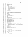
APPENDIX A
MI CROL CCNP [Lt-1R VERSION 1-5
2
MODULE
TJHMI
Edi t
:
H
q
1
a
i
I
5
G
7
8
9
10
1t
12
13
1s
l5
16
Hq
l8
19
2|]
21
22
23
24
2'5
26
27
DQOCIJGEU
It
i
It
44
a
*
'i
*
\
Created By: TIM
Dat e Last Edited: ‘JED .
Last Edited By 2 TIM
FEB
20 .
198i] v
6: ()1
Q
'
Q
PM
i Date Last: Compiled/Assembled: LIED, FEB 2D.
'1 Last Compiled/Assembled By: TIM
1980.
n
6208 PM
I
'1
a
I)
CONSTANT
TRUEIIiFALSEIO;
AUCMAX=3DGO 3
(
l‘ INHINZIODU;
HINMAKIZBUO i
MINCONZS;
MSTARTII-O;
NMAXIQ-U;
HMIN=0-1 i
UP=1 HZDUNIO i
SLDP‘-'231
SCALEZIZB-IH
MAXTIHZ6DD0§
MINT IM=3UU1
DELMINISOUI
VLVMAX=8DD§
SPLDLYIZD;
AVECONIE?
IH {6H REVE'RSAL F0 INT
H
(*MINIMUM LOH REVERSAL P0 INT“)
(*MAX. LOH REVERSAL POINT.)
( *AUTORANGING SCALE CONSTANT‘P)
(‘STARTING VAL. OF d(VALVE)/d(FLDH) i)
(*MAX VALUE OF d(VALVE)/d(FLOH) 1')
1* MIN‘ VALUE OF d(VALVE)/d(FLOH) *)
,
(*FIXUP CONST. FOR PLAY IN VALVE COUPLING*)
(*CDNVERSION CONST TO GET CC/HIN. FLOH i)
(‘MAXIMUM SAMPLE T IHE IN .5 niS 0)
( *MINIMUN SAMPLE DURATION IN .5 mS*)
( *MIN. READ IND DIFFERENCE FCR ALL OHABLE SAHPLE*)
(*"AXIMUP'I VALVE POSITIGN IN STEPS FROM CLOSED 1)
FOR DELAY BEFORE STARTING SAMPLE*I
( ‘CONST
(*CONST - FOR 1/2 NO - 0F CONVERSIONS PER READING‘)


![[l] STORAGE](http://vs1.manualzilla.com/store/data/005949981_1-aa131963b29a7cfe7d43fe9de2ac578c-150x150.png)